Note: Descriptions are shown in the official language in which they were submitted.
CA 02927997 2016-04-14
WO 2015/058142
PCT/US2014/061234
GAP-BASED DATA TRANSMISSION MANAGEMENT FOR AT BIT
MEASUREMENT TOOL
FIELD
Embodiments disclosed herein relate to data transmission using electrical
isolation joints
(e.g., gaps). More particularly, embodiments disclosed herein relate to using
electrical isolation
joints that are normally closed to provide drillstring integrity when not
transmitting data. Data
transmission is managed by opening the gap to transmit signals, and closing
the gap when the
transmission is complete.
BACKGROUND
Measurement while drilling ("MWD") tools are generally used during drilling
for taking
directional surveys in real time. For a directional driller to steer the well
towards a target zone,
the driller must know where the well is going, and the effects of his or her
steering efforts.
MWD tools often incorporate electrical insulators in the drillstring to
transmit data. The tool
generates an altered voltage difference between the top part (i.e., the main
drillstring, above the
electrical insulator), and the bottom part (i.e., the drill bit, and other
tools located below the
electrical insulator). At the surface, a wire is attached to the wellhead,
which makes contact with
the drillstring. A second wire is attached to a rod driven into the ground
some distance away.
The wellhead and the ground rod form two electrodes of a dipole antenna. The
voltage
difference received between the two electrodes is received by a computer and
decoded.
Electrical insulators (e.g., electrical gaps) may be used for both downhole-to-
surface
communication (i.e., the signal is transmitted to the surface) and downhole-to-
downhole
communication (i.e., the signal is transmitted to a downhole location). In
certain applications,
two or more electrical insulators may be employed to accomplish both downhole-
to-surface and
1
CA 02927997 2016-04-14
WO 2015/058142
PCT/US2014/061234
downhole-to-downhole communication simultaneously. In this case, the existence
of one
electrical insulator may adversely affects the performance of the other
electrical insulators.
For an electrical insulator to work properly, the drillstring and the
underground formation
must form a conducting path through drilling mud so that an electrical current
can be driven
across the electrical insulator. This generally is not a concern for wellbores
drilled with salty or
conducting muds because the muds adequately conduct electrical current.
However, conducting
an electrical current through oil-based or other non-conducting muds may be
more difficult. For
a BHA employing a single electrical insulator, the drill bit often provides a
viable contact point
between the drillstring and the formation through which electrical current may
flow from the
electrical insulator through the drillstring to the formation, and return to
the drillstring on the
other side of the electrical insulator.
But, for a BHA employing two or more electrical insulators, lower electrical
insulators
(closer to the bit) may break or impede the path of current flowing from the
upper electrical
insulator that relies on the drill bit as the contact point. What is needed
then is an apparatus and
method having multiple electrical insulators that may be operated
simultaneously without
adversely affecting others' operation.
SUMMARY
In one aspect, embodiments disclosed herein relate to a bottom hole assembly
attached to
a drillstring including a main body having a first electrical insulator
section separating a first
body portion from a second body portion, a second electrical insulator section
separating the
second body portion from a third body portion, and a circuit element connected
across the second
electrical insulator section. The circuit element is configured to be closed
and provide an
electrical current path across the second electrical insulator section upon a
voltage signal at a
first frequency being generated across the first electrical insulator section,
and the circuit element
2
CA 02927997 2016-04-14
WO 2015/058142
PCT/US2014/061234
is configured to be opened and break said electrical current path across the
second electrical
insulator section upon a voltage signal at a second frequency being generated
across the second
electrical insulator section.
In other aspects, embodiments disclosed herein relate to a method of
transmitting data
using a two sub gap-based downhole tool including a first measurement system
having a first sub
gap for transmitting data to surface, and a second measurement system having a
second sub gap
for transmitting data to the first measurement system, the method including
transmitting data at
any time from only one of the first measurement system or second measurement
system, and
dividing data transmitting times between the first and second measurement
systems whereby
each measurement system is instructed when and when not to transmit data, the
second
measurement system overriding the first measurement system in the event of a
conflict.
In yet other aspects, embodiments disclosed herein relate to a bottom hole
assembly for
transmitting data including a first measurement system having a first sub gap
configured to
transmit data to a surface receiver and a second measurement system having a
second sub gap
configured to transmit one-way data to the measurement while drilling system,
wherein the
second measurement system is configured to override the first measurement
system when
transmitting data.
BRIEF DESCRIPTION OF THE DRAWINGS
The invention is illustrated in the accompanying drawings wherein,
Figure 1 illustrates a conventional drilling rig on which exemplary
embodiments of the
apparatus and methods disclosed herein may be utilized.
Figure 2 illustrates a bottom hole assembly in accordance with one or more
embodiments;
3
CA 02927997 2016-04-14
WO 2015/058142
PCT/US2014/061234
Figure 3 illustrates an inductor connected across an electrical insulator
section in
accordance with one or more embodiments;
Figure 4 illustrates an equivalent circuit of Figure 3;
Figure 5 illustrates a capacitor connected across an electrical insulator
section in
accordance with one or more embodiments; and
Figure 6 illustrates an equivalent circuit of Figure 5.
Figure 7 illustrates an embodiment of a two sub gap-based downhole tool.
Figure 8 illustrates a schematic for operating the two sub gap-based downhole
tool.
Figure 9 illustrates a flowchart of a method for communicating data by
telemetry.
DETAILED DESCRIPTION
The aspects, features, and advantages of the invention mentioned above are
described in
more detail by reference to the drawings, wherein like reference numerals
represent like
elements.
A bottom hole assembly (BHA), such as a measurement-while-drilling (or "MWD")
tool
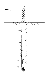
for performing drilling related measurements downhole is disclosed. Figure 1
illustrates a
drilling assembly 10 in which the bottom hole assembly described herein may be
deployed. A
drilling rig 12 including a derrick and platform is positioned at the surface
11 over an oil and gas
formation 13 disposed therebeneath. A drillstring 14 have a drill bit 15 on
end thereof extends
from the drilling rig 12 into a borehole 16 in the formation 13. The
drillstring 14 may include
any number of downhole tools including, for example, measurement while
drilling 18 ("MWD")
tools, logging while drilling 20 ("LWD") tools, stabilizers (not shown), a
rotary steerable tool
(not shown), a downhole drilling motor 22, and one or more at-bit sensors 24.
It should be
understood that the bottom hole assembly described herein in accordance with
one or more
embodiments is useful in any type of drilling operation, either onshore or
offshore. Moreover,
4
CA 02927997 2016-04-14
WO 2015/058142
PCT/US2014/061234
the bottom hole assembly described herein may be used in operation other than
drilling, for
example, wireline.
The bottom hole assembly disclosed herein may provide information about the
conditions
at the drill bit, such as rotational speed of the drillstring, smoothness of
the drillstring rotation,
type and severity of any downhole vibrations, downhole temperatures, torque
and weight on bit,
mud flow volume, and others. The tool may be coupled with or used with any
other downhole
tools, including but not limited to, mud motors, rotary steerable systems, and
logging-while-
drilling (or "LWD") tools. The BHA may include an electromagnetic (EM)
transmitter, which
collects drilling and geological data related to the drilling operation, and a
receiver for receiving
data from the transmitter and which subsequently sends the received drilling
and geological data
to a remote location, either at the surface or downhole, where the data is
collected and analyzed.
The BHA may include multiple electrical insulators disposed along a length
thereof The
electrical insulators may be composed of an insulating material to permit the
passage of EM
radiation therethrough. The insulating materials may include a class of
polyetherketones or other
suitable resins. For example, fiberglass-epoxy, PEK and PEEK are dielectric
materials or resins
that permit the passage of signal energy including electromagnetic radiation.
In certain
embodiments, the BHA may include two electrical insulators that serve
different purposes (e.g.,
one for downhole-to-surface communication and the other for downhole-to-
downhole
communication). The two electrical insulators may operate simultaneously
although
independently of each other. For example, a first electrical insulator may
remain electrically
shorted while a second electrical insulator operates. As used herein, operates
means transmitting
or generating a voltage signal across the electrical insulator for
communicating data to a remote
or separate location, as will be understood by those skilled in the art. The
above described
5
CA 02927997 2016-04-14
WO 2015/058142
PCT/US2014/061234
apparatus may alternatively be configured to include any number of multiple
electrical insulator
sections. An electrical insulator section that is transmitting or generating a
signal may remain
"open," i.e., a voltage difference is generated across the insulator section.
Any remaining
electrical insulator sections may be electrically shorted. The remaining
electrical insulator
sections may be non-transmitting electrical insulator sections in certain
embodiments. As used
herein, "across" or "there across" in reference to the electrical insulator
sections may refer to an
axial length of the electrical insulator sections, from substantially a first
end of the section to an
opposite or second end of the section. An axial length of the electrical
insulator sections is in
reference to a central axis of the drillstring or tool body in which the
electrical insulator sections
are disposed.
One or more electrical insulator sections may be electrically shorted by way
of a circuit
element connected across one or more or each of the multiple electrical
insulator sections in
accordance with one or more embodiments. In certain embodiments, more than one
circuit
element may be connected across one or more of the multiple electrical
insulator sections. The
circuit elements may include inductors, capacitors, resistors, and others, and
any combination
thereof The circuit elements may be configured to selectively "short" (e.g.,
provide or create an
electrical circuit that allows a current to travel along the circuit element
where no or very little
electrical impedance is encountered) one or more of the multiple electrical
insulator sections. A
resonance frequency may be selected and matched for each of the circuit
elements, so that at a
particular resonance frequency, a circuit element in an electrical insulator
section produces an
impedance suitable for generating a voltage signal for communicating data.
However, at that
same resonance frequency, other circuit elements in other electrical insulator
sections are
selected so that little to no impedance is produced, thereby shorting the
other electrical insulator
6
CA 02927997 2016-04-14
WO 2015/058142
PCT/US2014/061234
sections. Accordingly, multiple resonance frequencies may be selected, each of
which may be
implemented with one or more of the multiple circuit elements. The multiple
resonance
frequencies may be separated by a sufficient frequency range (e.g., 10Hz) to
avoid accidently
shorting and opening unintended electrical insulator sections.
Figure 2 illustrates a downhole tool or BHA 100 in accordance with one or more
embodiments. The BHA includes two electrical insulator sections, an upper
electrical insulator
section 106 and a lower electrical insulator section 108. The upper electrical
insulator section
106 may be used for downhole-to-surface communication, and the lower
electrical insulator
section 108 may be used for downhole-to-downhole communication. The signals
generated for
downhole-to-surface communication usually travel over a much longer distance
than those for
downhole-to-downhole communication. Because of this, a voltage signal
generated across the
upper electrical insulator section 106 may be a low-frequency signal. For
example, a low-
frequency signal may be at least 1 Hz, or at least 2 Hz, or at least 5 Hz, and
up to 7 Hz, or up to 8
Hz, or up to 10 Hz. A voltage signal generated across the lower electrical
insulator section 108
may be a high-frequency signal. For example, a high-frequency signal may be at
least 500 Hz,
or at least 1000 Hz, or at least 1500 Hz, or at least 2000 Hz, and up to 3000
Hz, or up to 4000
Hz, or up to 4500 Hz, or up to 5000 Hz.
The lower electrical insulator section 108 serves as termination of the BHA
for the upper
electrical insulator section 106. For oil-based mud through which electrical
current does not
travel easily, this implies that the drill bit 104 contact with the formation
is effectively removed
from the electrical current path for the upper electrical insulator section
106. To maintain the
electrical current continuity through the lower electrical insulator section
108 when the upper
electrical insulator section 106 transmits, the lower electrical insulator
section 108 remains
7
CA 02927997 2016-04-14
WO 2015/058142
PCT/US2014/061234
electrically shorted when a voltage signal is generated across the upper
electrical insulator
section 106. On the other hand, the lower electrical insulator section 108 is
open (i.e., not
electrically shorted) when a voltage signal is generated across the lower
electrical insulator
section 108.
Referring to Figure 3, a circuit element, for example an inductor 110, is
connected across
the lower electrical insulator section 108. A voltage signal generated across
the upper electrical
insulator section 106 travels downward along the drillstring until the signal
or current encounters
the lower electrical insulator section 108. The voltage signal travels across
the lower electrical
insulator section 108 through the inductor 110. The impedance of the
electrical insulator section
is calculated according to joL, wherein j is the square root of (-1), co is
the frequency of the
voltage source, and L is inductance (measured in Henrys). So long as the
frequency of the
voltage signal is sufficiently low, the electrical insulator section impedance
will be negligible.
Accordingly, the electrical insulator section is electrically shorted.
Figure 4 illustrates an equivalent circuit 400 for the lower electrical
insulator section 108
including an inductor 110 shown in Figure 3. Rgap is the resistance "seen" by
the lower electrical
insulator section 108 across the electrical insulator section 108 without the
inductor 110. Rgap
depends on the resistivity of the formation around the wellbore, the
resistivity of drilling mud,
the size of the borehole, and the length of the electrical insulator section,
among others. For
simplicity, the resistance of the inductor 110 has been omitted. The total
impedance of the circuit
is calculated using the following equation:
pLoLRgap
Z = Equation (1)
For a sufficiently larger value of L, the total impedance across the lower
electrical
insulator section 108 approaches Rgap. As an example, one may assume Rgap =10
ohms and
8
CA 02927997 2016-04-14
WO 2015/058142
PCT/US2014/061234
L=10mH. Then, for a frequency of 3 kHz, Z=9.97+j0.53 ohm Rgap. Lowering the
frequency
will introduce a larger reactance component to the total impedance. For
instance, at 1 kHz,
Z=9.75+j1.55 ohm. The reactance part will be about 16% of the resistance.
In other embodiments, the circuit element may include a capacitor shown in
Figure 5.
Figure 6 illustrates an equivalent circuit 600 for the lower electrical
insulator section 108
including a capacitor 112 shown in Figure 5. A total impedance of the circuit
shown in Figure 6
is calculated using the following equation:
Rgap
Z = Equation (2)
1,1-6.,==LC)Figaptiwl.
At very low frequencies:
Z jcoL Equation (3)
That is, the electrical insulator section may effectively be electrically
shorted because of
the low impedance. At very high frequencies:
Z Equation (4)
The electrical insulator section then behaves as a capacitor. If frequency is
chosen such
that:
0.)L.C. 1 Equation (5)
then the impedance may be calculated as:
Z = Rgap Equation (6)
Equation (5), or the resonance frequency, causes the L-C branch (e.g., the
circuit branch
including the inductor/capacitor) of the circuit to resonate, which
electrically opens the electrical
insulator section for the frequency. For instance, to drive the electrical
insulator section at 1 kHz
would require LC = 2.53 x 10-s. For L=10mH, a capacitor with C=2.53 F may be
chosen.
9
CA 02927997 2016-04-14
WO 2015/058142
PCT/US2014/061234
One or more embodiments disclosed herein relate to a bottom hole assembly
attached to a
drillstring including a main body including a first electrical insulator
section separating a first
body portion from a second body portion, a second electrical insulator section
separating the
second body portion from a third body portion, and a circuit element connected
across the second
electrical insulator section. The circuit element is configured to be closed
and provide an
electrical current path across the second electrical insulator section upon a
voltage signal at a
first frequency being generated across the first electrical insulator section.
The circuit element is
configured to be opened and break said electrical current path across the
second electrical
insulator section upon a voltage signal at a second frequency being generated
across the second
electrical insulator section.
Other embodiments disclosed herein relate to a bottom hole assembly attached
to a
drillstring including a main body including multiple electrical insulator
sections along a length
thereof and a circuit element connected across each of said multiple
electrical insulator sections.
Each of said multiple electrical insulator sections are configured to have a
voltage difference
generated there across. The circuit element of an electrical insulator section
having a voltage
difference at a first frequency generated there across is configured to not
allow an electrical
current to travel there across. The circuit elements of all remaining
electrical insulator sections
not having said voltage difference at said first frequency generated there
across are configured to
allow an electrical current to travel there across.
Yet other embodiments disclose a method of selectively transmitting a signal
generated
from multiple electrical insulator sections for providing downhole
measurements including
providing a tool body including multiple electrical insulator sections
disposed along a length
thereof, generating a voltage signal at a first frequency across one of the
multiple electrical
CA 02927997 2016-04-14
WO 2015/058142
PCT/US2014/061234
insulator sections, providing an electrical current path across all remaining
electrical insulator
sections not having said voltage signal at said first frequency generated
there across, and
transmitting said signal relating to said generated voltage signal to a
location apart from said tool
body.
In yet other embodiments, Figure 7 illustrates a system 100 that includes a
first
measurement system also described as an MWD system 110 located above a mud
motor 120 and
a second measurement system or an "At-Bit" measurement system 130, which is
below the mud
motor. The MWD system 110 has a sub gap 115 for electromagnetic (EM) telemetry
to transmit
data to surface, while the At-Bit system 130 has a gap 135 located below the
mud motor 120 for
short range EM telemetry to transmit data to MWD system. The short range EM
telemetry from
gap 135 provides one way communication of At-Bit measurements to the MWD
system above
the mud motor. Measurements by the At-Bit system 130 may include, but are not
limited to,
azimuthal natural gamma ray imaging, azimuthal resistivity imaging, RPM and
inclination
measuring, and other measurements known to one skilled in the art. Because the
gap 135 is
formed by insulating two adjacent subs, no electrical continuity is provided
while it functions for
short range telemetry purposes. The existence of the lower At-Bit sub gap 135
also breaks the
electrical connection between a drill bit 140 and the sub gap 115 of the MWD
system 110. This
discontinuity may affect the performance of the MWD system above the mud
motor. The At-Bit
sub gap 135 is by default normally electrically closed, and is controlled by
the At-Bit system and
shared by both the At-Bit system and the MWD system. At any time, only one
system, either
At-Bit system 130 or the MWD system 110, may use this At-Bit gap 135. For
example, when
the telemetry system of the At-Bit system is broadcasting, the MWD system
won't be able to
transmit during that time. The At-Bit system functions as a master which
dominates the
11
CA 02927997 2016-04-14
WO 2015/058142
PCT/US2014/061234
communication and the MWD system functions as a slave system which listens to
the master and
transmit only when it's allowed. How to divide time is predefined and
configured in both MWD
and At-Bit systems before the operation so that both systems will know exactly
when to transmit
and when to keep silent. And the time division may not be equal since the data
rate requirements
for two systems may not be the same. Since normally the MWD system has a lower
data rate due
to its long distance transmission, more time may need to be assigned
accordingly.
Methods of using the system 100 allow the functioning of two sub gap based
dovvnhole
systems with the At-Bit system as the master to dominate the time
synchronization. Since the
time slot or available transmission time is assigned to MWD and At-Bit in
advance, once the
time is synced on both systems they will know when to transmit and when to
keep silence. For
example, if the MWD system sees At-Bit system's signal and is synchronized,
this time may be
used as the reference to calculate the time it can transmit. The At-Bit system
130 may run
continuously to acquire data from sensors and perform measurement and
processing. When time
for the At-Bit system 130 to broadcast its measurement results, the data is
packaged and sent to
the telemetry unit of the At-Bit system. The telemetry unit then switches the
At-Bit gap 135 to
open and the signal is output to the gap. The measurement result is also
stored in the memory of
the At-Bit system 130.
Data sent by the At-Bit system 130 is started by the sync signal (header), a
known pattern
of signal which the MWD receiver knows that it is the start of the At-Bit
broadcasting message.
When the MWD system 110 receives the sync header and is synced with the signal
from the At-
Bit system 130, the MWD system 110 begins accepting data. Because this is a
one way
communication, the message may be embedded with the information regarding the
time slot
length or data length. In this way, after the MWD system 110 finishes
receiving data before the
12
CA 02927997 2016-04-14
WO 2015/058142
PCT/US2014/061234
expiration of the assigned time slot, it can transition to a power saving
mode. In this system, the
MWD system 110 always listens to the signal from the At-Bit system 130 and
syncs with the At-
Bit system 130 each time the message is received from the At-Bit system 130.
Figure 8 illustrates a schematic for operating a two sub gap-based downhole
system.
Upon system start (step 800), data acquisition begins (step 802) followed by
data processing
(step 804). A query is sent as to whether it is time to broadcast data (step
806). If yes, data is
broadcast through any communications process (e.g., telemetry) (step 808). If
no, a query is sent
as to whether it is time to record data (step 810). If yes, data is recorded
to memory (step 812). If
no, the system continues acquiring data (step 802).
Figure 9 illustrates a flowchart for a method of communicating data by
telemetry (see
step 820 in Figure 8). Telemetry starts (step 822), a gap switch is opened
(step 824) and
transmitter is turned on (step 826). After waiting for the signal to stabilize
(step 828), a sync
header is sent (step 830), followed by a time slot length (step 832), data
header (step 834), data
(836), and a checksum (838). The transmitter is turned off (step 840), and the
gap switch is
closed (step 842), which completes the transmission (step 844).
Advantageously, embodiments of the system 100 disclosed herein provide higher
efficiency gap-based transmission and drillstring integrity for EM MWD
communications with
the surface, and for LWD measurements.
The claimed subject matter is not to be limited in scope by the specific
embodiments
described therein. Indeed, various modifications of one or more embodiments
disclosed herein
in addition to those described herein will become apparent to those skilled in
the art from the
foregoing descriptions. Such modifications are intended to fall within the
scope of the appended
claims.
13
CA 02927997 2016-04-14
WO 2015/058142
PCT/US2014/061234
As used in this specification and the following claims, the terms "comprise"
(as well as
forms, derivatives, or variations thereof, such as "comprising" and
"comprises") and "include"
(as well as forms, derivatives, or variations thereof, such as "including" and
"includes") are
inclusive (i.e., open-ended) and do not exclude additional elements or steps.
Accordingly, these
terms are intended to not only cover the recited element(s) or step(s), but
may also include other
elements or steps not expressly recited. Furthermore, as used herein, the use
of the terms "a" or
"an" when used in conjunction with an element may mean "one," but it is also
consistent with
the meaning of "one or more," "at least one," and "one or more than one."
Therefore, an element
preceded by "a" or "an" does not, without more constraints, preclude the
existence of additional
identical elements.
The use of the term "about" applies to all numeric values, whether or not
explicitly
indicated. This term generally refers to a range of numbers that one of
ordinary skill in the art
would consider as a reasonable amount of deviation to the recited numeric
values (i.e., having
the equivalent function or result). For example, this term can be construed as
including a
deviation of 10 percent of the given numeric value provided such a deviation
does not alter the
end function or result of the value. Therefore, a value of about 1% can be
construed to be a
range from 0.9% to 1.1%.
14