Language selection

Search

Patent 2928490 Summary

Third-party information liability

Some of the information on this Web page has been provided by external sources. The Government of Canada is not responsible for the accuracy, reliability or currency of the information supplied by external sources. Users wishing to rely upon this information should consult directly with the source of the information. Content provided by external sources is not subject to official languages, privacy and accessibility requirements.

Claims and Abstract availability

Any discrepancies in the text and image of the Claims and Abstract are due to differing posting times. Text of the Claims and Abstract are posted:

  • At the time the application is open to public inspection;
  • At the time of issue of the patent (grant).
(12) Patent: (11) CA 2928490
(54) English Title: METHOD OF FORMING A TRAILER HITCH RECEIVER TUBE
(54) French Title: METHODE DE FACONNAGE D'UN TUBE RECEPTEUR D'ATTACHE DE REMORQUE
Status: Granted and Issued
Bibliographic Data
(51) International Patent Classification (IPC):
  • B21D 53/88 (2006.01)
  • B60D 01/145 (2006.01)
(72) Inventors :
  • FORTE, MARIO (Canada)
  • FORTE, JON RYAN (Canada)
(73) Owners :
  • JEFFERSON METAL PRODUCTS INC.
(71) Applicants :
  • JEFFERSON METAL PRODUCTS INC. (Canada)
(74) Agent: MOFFAT & CO.
(74) Associate agent:
(45) Issued: 2018-07-17
(22) Filed Date: 2016-04-29
(41) Open to Public Inspection: 2017-10-03
Examination requested: 2017-07-18
Availability of licence: N/A
Dedicated to the Public: N/A
(25) Language of filing: English

Patent Cooperation Treaty (PCT): No

(30) Application Priority Data: None

Abstracts

English Abstract

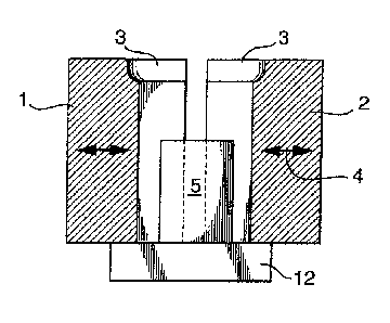
A method of manufacturing a trailer hitch receiver tube with an integral reinforcing collar is described. A two piece die having an interior shape and dimensions conforming to the shape and dimensions of a selected trailer hitch receiver tube is provided, the two pieces of the die being a right half and a left half. Each of the right and left halves of the die are provided with means to forcefully move the die from an open position to a closed position around a workpiece. The die, around an upper edge thereof is provided with a relief cavity around its perimeter having the shape of a reinforcement collar. A base mandrel is provided between the right and left halves of the die, the base mandrel having a size and shape conforming to the size and shape of the interior of a trailer hitch receiver tube, and the base mandrel having a height less than the die. A steel receiver tube is positioned on the base mandrel, the tube having a height greater than the die halves. The die halves are then closed forcefully against the receiver tube. A forming mandrel is provided above the receiver tube. The forming mandrel has a longitudinal portion that conforms in shape to the interior of the receiver tube, and a lateral, forming portion for bearing against the upper edge of the receiver tube to form the upper portion of a receiver tube into a reinforcing collar by deforming the upper end of said tube into the relief cavity. An upper edge of the receiver tube is then forcefully struck with the forming portion of the forming mandrel, to form the collar, wherein the longitudinal portion of the forming mandrel closely approaches an upper surface of the base mandrel after the collar is formed.


French Abstract

Un procédé de fabrication dun tube de réception de dispositif dattelage de remorque avec un collier de renfort intégré est décrit. Une matrice à deux pièces ayant une forme intérieure et des dimensions épousant la forme et les dimensions dun tube récepteur de dispositif dattelage de remorque sélectionné est prévue, les deux pièces de la matrice étant une moitié droite et une moitié gauche. Chacune des moitiés droite et gauche de la matrice est pourvue de moyens permettant de déplacer la matrice avec force dune position ouverte à une position fermée autour dune pièce à travailler. La matrice, autour dun bord supérieur de celle-ci, est pourvue dune cavité de détente autour de son périmètre ayant la forme dun collier de renfort. Un mandrin de base est disposé entre les moitiés droite et gauche de la matrice, le mandrin ayant une dimension et une forme épousant la dimension et la forme de lintérieur dun tube récepteur de dispositif dattelage de remorque, et le mandrin ayant une hauteur inférieure à celle de la matrice. Un tube récepteur en acier est positionné sur le mandrin de base, le tube ayant une hauteur supérieure à celle des moitiés de la matrice. Ces dernières sont alors fermées avec force contre le tube récepteur. Un mandrin de formage est disposé au-dessus du tube récepteur. Le mandrin de formage comporte une partie longitudinale qui épouse la forme de lintérieur du tube récepteur et une partie de formage latérale pour reposer contre le bord supérieur du tube récepteur afin de former la partie supérieure dun tube récepteur dans un collier de renfort en déformant lextrémité supérieure dudit tube dans la cavité de détente. Un bord supérieur du tube récepteur est alors frappé avec force avec la partie de formage du mandrin de formage, pour former le collier, la partie longitudinale du mandrin de formage approchant près dune surface supérieure du mandrin de base une fois le collier formé.

Claims

Note: Claims are shown in the official language in which they were submitted.


6
CLAIMS
1. A method of manufacturing a trailer hitch receiver tube with an
integral
reinforcing collar comprising the steps of:
i) providing a two piece die having an interior shape and dimensions
conforming to a shape and dimensions of a selected trailer hitch
receiver tube, the two pieces of said die being a right half and a
left half, each of said right and left halves of said die being
provided with means to forcefully move said die from an open
position to a closed position around a steel receiver tube
workpiece, said die around an upper edge thereof being provided
with a relief cavity around its perimeter having a shape of a
reinforcement collar;
ii) providing a base mandrel between said right and left halves of
said die said base mandrel having a size and shape conforming
to the size and shape of an interior of the steel receiver tube
workpiece, wherein said base mandrel having a height less than
the height of the two piece die;
iii) positioning the steel receiver tube workpiece on said base
mandrel, said tube having a height greater than said die halves;
iv) closing said die halves forcefully against said receiver tube
workpiece;
v) providing a forming mandrel above said steel receiver tube
workpiece, said forming mandrel having a longitudinal portion that
conforms in shape to the interior of said receiver tube workpiece,
and a lateral, forming portion for bearing against an upper edge
of said receiver tube to form the upper portion of said steel
receiver tube workpiece into a reinforcing collar by deforming the
upper end of said steel tube workpiece into said relief cavity, and
forcefully striking said upper edge of said receiver steel tube
workpiece with the lateral forming portion of said forming mandrel,
to form said reinforcing collar, wherein the longitudinal portion of
said forming mandrel closely approaches an upper surface of said

7
base mandrel thereby forming the trailer hitch receiver tube with
the integral reinforcing collar.
2. A method as
claimed in claim 1, wherein the height of said base mandrel
is about half the height of said die.

Description

Note: Descriptions are shown in the official language in which they were submitted.


CA 02928490 2016-04-29
METHOD OF FORMING A TRAILER HITCH RECEIVER TUBE
The present invention relates to the field of metal forming. In particular,
the
present invention provides an improved method of forming a trailer hitch
receiver tube.
A receiver tube is a robust, rigid tube, made of steel or other suitable metal
that
is permanently or semi-permanently affixed to the rear of a vehicle. Its
purpose is to
accept a sleeve and ball trailer hitch, which is inserted into the receiver,
and held there
by a laterally extending pin that goes through both the receiver tube and the
sleeve and
ball hitch. A trailer can then be attached to the hitch.
In order to strengthen a receiver tube, it has, for years, been the practice
to affix
by welding, a reinforcement collar, made of steel, to the rearward projecting
end of the
receiver tube. Recently, however, receiver tubes have been designed with
integral
collars. A typical design of a receiver tube with an integral collar is shown
in US 6408672
to Roe. In that patent, a receiver tube with an integral collar is produced by
inserting a
steel tube into the open end a die conforming to the outer profile of the
tube. The die has
a cavity shaped like a collar at its outer end, and stop means to prevent
movement of
the tube longitudinally in the die. The stop means comprises a rigid floor to
the die, so
that pressure on the tube at the open end of the die will not force the tube
through the
die. A T-shaped mandrel is then lowered into the tube, with the body of the
mandrel
conforming to the interior dimension of the tube to support same against
collapse under
pressure. When the head of the T-shaped mandrel contacts the end of the tube,
high
pressure is then applied by the mandrel, to deform the end of the tube into
the collar
shaped cavity. As the mandrel advances, it supports the walls of the tube from
deforming.
However, as the mandrel advances, the inner end of the tube is substantially
unsupported at the moment the head of the mandrel contacts the end of tube.
Therefore,
in practice, when the method of US 6408672 is carried out. Pressure is applied
gradually,
so that the inner end of the tube, which is supported on its outside, if not
on its inside,
surfaces, will tend not to buckle. With a faster impact to the outer end of a
cold tube,
there is a greater tendency for the impact to be absorbed along the entire
length of the
tube, and so to cause deformation of the partially supported inner end, as
well as the
unsupported outer end. It will be noted, in this regard, that this tendency is
countered to

2
some extend by the closed shape of the tube, which will tend to direct forces
outwardly
rather than inwardly. However, in this regard, the inner end of the tube may
still deform
under a high load.
The present invention is an improvement over the process of US 6408672. In the
present invention, a different form of die is provided for a steel tube than
is provided in
US 6408672. In the present invention, a two piece die is provided, with right
and left
sides that come together under pressure to hold a steel tube firmly in
position against
axial movement. When the die halves come together, they define a longitudinal
space
dimensioned to exactly hold a suitable steel tube, and are provided with a
relief cavity at
their upper end, whereby the end of the steel tube may be deformed into the
relief cavity.
Utilizing the two part mold as in the method of the present invention,
prevents
deformation anywhere other than the end of the tube that extends from the
mold.
In the method of the present invention, the tube is inserted onto a stationary
mandrel that extends upwardly from a solid surface. The mold halves may then
be closed
around the tube, using a T-shaped mandrel with an upper surface adopted to
strike the
end of the tube, and a length selected to almost meet the stationary mandrel
when the
end of the tube is fully deformed into the relief cavity. In this case, the
only unsupported
inner wall surface of the tube is the short length of wall between the two
mandrels, the
stationary mandrel and the T-shaped mandrel. This position of the steel tube
is less likely
to deform than the unsupported inner end of the tube in US 6408672, because
each end
of this portion is integral with and therefore axially supported by the
portions of the tube
above and below it.
The result, using this arrangement, is a tube with a collar that may be formed
faster than using the method of US 6408672. Because the end of the tube does
not need
to be heated, the tube can be struck rather than gradually pressed. Moreover,
a high
degree of quality control is ensured, because the chance of deforming the
other end of
the tube is minimized.
In a broad aspect, moreover, the present invention provides a method of
manufacturing a trailer hitch receiver tube with an integral reinforcing
collar comprising
CA 2928490 2018-03-02

3
the steps of: (i) providing a two piece die having an interior shape and
dimensions
conforming to a shape and dimensions of a selected trailer hitch receiver
tube, the two
pieces of said die being a right half and a left half, each of said right and
left halves of
said die being provided with means to forcefully move said die from an open
position to
a closed position around a steel receiver tube workpiece, said die around an
upper edge
thereof being provided with a relief cavity around its perimeter having a
shape of a
reinforcement collar; (ii) providing a base mandrel between said right and
left halves of
said die said base mandrel having a size and shape conforming to the size and
shape
of an interior of the steel receiver tube workpiece, wherein said base mandrel
having a
height less than the height of the two piece die; (iii) positioning the steel
receiver tube
workpiece on said base mandrel, said tube having a height greater than said
die halves;
(iv) closing said die halves forcefully against said receiver tube workpiece;
(v) providing
a forming mandrel above said steel receiver tube workpiece, said forming
mandrel
having a longitudinal portion that conforms in shape to the interior of said
receiver tube
workpiece, and a lateral, forming portion for bearing against an upper edge of
said
receiver tube to form the upper portion of said steel receiver tube workpiece
into a
reinforcing collar by deforming the upper end of said steel tube workpiece
into said relief
cavity, and forcefully striking said upper edge of said receiver steel tube
workpiece with
the lateral forming portion of said forming mandrel, to form said reinforcing
collar, wherein
the longitudinal portion of said forming mandrel closely approaches an upper
surface of
said base mandrel thereby forming the trailer hitch receiver tube with the
integral
reinforcing collar.
In drawings that illustrate the present invention by way of example.
Figure 1 is a side sectional view of a pair of dies in an open position over a
base
mandrel.
Figure 2 is a side sectional view of the pair of dies of Figure 1, closed on a
steel
tube, with a forming mandrel partly inserted into the tube.
Figure 3 is a view of the arrangement of Figure 2, with the forming mandrel
fully
extended, having struck and deformed the end of the steel tube.
CA 2928490 2018-04-27

4
Referring first to Figures 1 to 3, in a first embodiment, a pair of mold
halves 1, 2
is provided. Each is provided at its upper edge with a relief cavity 3 shaped
to form a
reinforcement collar for a trailer hitch receiver tube.
As shown by arrows 4, the mold halves 1, 2 are moveable laterally. A base
mandrel 5 is provided on a base platform 12 between the two mold halves. Base
mandrel
is dimensioned to accept a steel tube 13, so that a steel tube 13 may be
positioned on
base mandrel 5, and the mold halves 1 and 2 closed tightly on the tube 13.
This will
immobilize the steel tube 13 with a portion of the tube extending above the
closed mold
halves. It will be understood that the length of steel tube 13 extending above
the closed
mold halves will be a length selected so that its total volume is equal to, or
slightly less
than, the total volume of the relief cavities in the mold halves.
As shown in Figure 3, a forming mandrel 9 is positioned above the mold halves,
aligned with the base mandrel 5. The forming mandrel 9 comprises a ram 7 for
powering
the forming mandrel in a downward direction, a support mandrel 6 for insertion
into the
steel tube 13, and a forming portion 10 for striking the upper end of the
steel tube to form
a collar 11 by deforming the upper end of the tube 13 into the relief cavity
3. As can be
seen in Figure 3, the length of the support mandrel 6 is such that at full
extension of the
forming mandrel 9, the support mandrel 6 is separated from base mandrel 5 by a
very
narrow gap, in the order of 1 mm. Forming mandrel 9 is then raised, the
finished product
is removed from the base mandrel 5, and the process can be repeated, as
desired.
With the method of the present invention, in which the collar is formed by
striking
the end of the tube, rather than gradually pressing the end, the collar of the
product as it
emerges from the mold is in finished condition. That is, deformation of the
tube end, and
folding of the tube end into the relief cavity is complete, without the need
for subsequent
grinding. This is thought to be because, with the gradual transfer of kinetic
energy from
the forming mandrel to the workpiece in the method of the prior art, folding
may not be
complete, and therefore, some of the steel of the end of the tube may remain
above the
relief cavity, and need to be ground down. With the method of the present
invention,
wherein the end of the tube is struck, the kinetic energy of the forming
mandrel is
CA 2928490 2017-11-27

CA 02928490 2016-04-29
transferred to the end of the pipe in a much smaller space of time, resulting
in increased
plasticity in the steel, which leads to better folding of the steel into the
relief cavity.
The result of the method of the present invention is therefore a high quality
trailer
hitch receiver tube, with an integrally formed reinforcement collar, that
requires no further
working.

Representative Drawing
A single figure which represents the drawing illustrating the invention.
Administrative Status

2024-08-01:As part of the Next Generation Patents (NGP) transition, the Canadian Patents Database (CPD) now contains a more detailed Event History, which replicates the Event Log of our new back-office solution.

Please note that "Inactive:" events refers to events no longer in use in our new back-office solution.

For a clearer understanding of the status of the application/patent presented on this page, the site Disclaimer , as well as the definitions for Patent , Event History , Maintenance Fee  and Payment History  should be consulted.

Event History

Description Date
Inactive: COVID 19 - Deadline extended 2020-03-29
Common Representative Appointed 2019-10-30
Maintenance Request Received 2019-04-17
Grant by Issuance 2018-07-17
Inactive: Cover page published 2018-07-16
Pre-grant 2018-06-01
Inactive: Final fee received 2018-06-01
Notice of Allowance is Issued 2018-05-17
Letter Sent 2018-05-17
Notice of Allowance is Issued 2018-05-17
Inactive: Approved for allowance (AFA) 2018-05-14
Inactive: QS passed 2018-05-14
Amendment Received - Voluntary Amendment 2018-04-27
Examiner's Interview 2018-03-19
Amendment Received - Voluntary Amendment 2018-03-02
Maintenance Request Received 2018-01-16
Inactive: S.30(2) Rules - Examiner requisition 2017-12-04
Inactive: Report - No QC 2017-12-01
Amendment Received - Voluntary Amendment 2017-11-27
Inactive: S.30(2) Rules - Examiner requisition 2017-10-04
Letter sent 2017-10-03
Application Published (Open to Public Inspection) 2017-10-03
Inactive: Report - No QC 2017-10-03
Advanced Examination Determined Compliant - paragraph 84(1)(a) of the Patent Rules 2017-10-03
Inactive: Cover page published 2017-10-02
Letter Sent 2017-08-10
Inactive: Office letter 2017-08-08
Inactive: Correspondence - Prosecution 2017-08-02
Inactive: Advanced examination (SO) fee processed 2017-08-02
Early Laid Open Requested 2017-08-02
Inactive: Advanced examination (SO) 2017-08-02
Inactive: Office letter 2017-07-25
Letter Sent 2017-07-24
Inactive: Advanced examination (SO) 2017-07-18
Request for Examination Requirements Determined Compliant 2017-07-18
All Requirements for Examination Determined Compliant 2017-07-18
Request for Examination Received 2017-07-18
Inactive: IPC assigned 2016-05-27
Inactive: First IPC assigned 2016-05-27
Inactive: IPC assigned 2016-05-27
Inactive: Filing certificate - No RFE (bilingual) 2016-05-04
Application Received - Regular National 2016-05-03

Abandonment History

There is no abandonment history.

Maintenance Fee

The last payment was received on 2018-01-16

Note : If the full payment has not been received on or before the date indicated, a further fee may be required which may be one of the following

  • the reinstatement fee;
  • the late payment fee; or
  • additional fee to reverse deemed expiry.

Patent fees are adjusted on the 1st of January every year. The amounts above are the current amounts if received by December 31 of the current year.
Please refer to the CIPO Patent Fees web page to see all current fee amounts.

Fee History

Fee Type Anniversary Year Due Date Paid Date
Application fee - standard 2016-04-29
Request for examination - standard 2017-07-18
Advanced Examination 2017-08-02
MF (application, 2nd anniv.) - standard 02 2018-04-30 2018-01-16
Final fee - standard 2018-06-01
MF (patent, 3rd anniv.) - standard 2019-04-29 2019-04-17
MF (patent, 4th anniv.) - standard 2020-04-29 2020-04-17
MF (patent, 5th anniv.) - standard 2021-04-29 2021-04-15
MF (patent, 6th anniv.) - standard 2022-04-29 2022-03-23
MF (patent, 7th anniv.) - standard 2023-05-01 2023-01-11
MF (patent, 8th anniv.) - standard 2024-04-29 2024-03-11
Owners on Record

Note: Records showing the ownership history in alphabetical order.

Current Owners on Record
JEFFERSON METAL PRODUCTS INC.
Past Owners on Record
JON RYAN FORTE
MARIO FORTE
Past Owners that do not appear in the "Owners on Record" listing will appear in other documentation within the application.
Documents

To view selected files, please enter reCAPTCHA code :


To view images, click a link in the Document Description column (Temporarily unavailable). To download the documents, select one or more checkboxes in the first column and then click the "Download Selected in PDF format (Zip Archive)" or the "Download Selected as Single PDF" button.

List of published and non-published patent-specific documents on the CPD .

If you have any difficulty accessing content, you can call the Client Service Centre at 1-866-997-1936 or send them an e-mail at CIPO Client Service Centre.

({010=All Documents, 020=As Filed, 030=As Open to Public Inspection, 040=At Issuance, 050=Examination, 060=Incoming Correspondence, 070=Miscellaneous, 080=Outgoing Correspondence, 090=Payment})


Document
Description 
Date
(yyyy-mm-dd) 
Number of pages   Size of Image (KB) 
Description 2016-04-28 5 202
Abstract 2016-04-28 1 36
Claims 2016-04-28 1 39
Drawings 2016-04-28 1 50
Representative drawing 2017-08-28 1 17
Description 2017-11-26 5 189
Description 2018-03-01 5 194
Claims 2018-03-01 1 40
Description 2018-04-26 5 202
Claims 2018-04-26 2 47
Maintenance fee payment 2024-03-10 1 25
Filing Certificate 2016-05-03 1 187
Acknowledgement of Request for Examination 2017-07-23 1 174
Reminder of maintenance fee due 2018-01-01 1 111
Commissioner's Notice - Application Found Allowable 2018-05-16 1 162
New application 2016-04-28 2 70
Request for examination / Advanced examination (SO) 2017-07-17 2 54
Courtesy - Office Letter 2017-07-24 1 58
Prosecution correspondence 2017-08-01 1 30
Advanced examination (SO) 2017-08-01 2 52
Early lay-open request 2017-08-01 2 52
Courtesy - Office Letter 2017-08-07 1 47
Courtesy - Acknowledgment of Refund 2017-08-09 1 46
Courtesy - Advanced Examination Request - Compliant (SO) 2017-10-02 1 47
Examiner Requisition 2017-10-03 6 355
Amendment / response to report 2017-11-26 5 208
Examiner Requisition 2017-12-03 3 192
Maintenance fee payment 2018-01-15 1 60
Amendment / response to report 2018-03-01 6 230
Interview Record 2018-03-18 1 58
Amendment / response to report 2018-04-26 6 191
Final fee 2018-05-31 1 48
Maintenance fee payment 2019-04-16 1 60
Maintenance fee payment 2020-04-16 1 25
Maintenance fee payment 2021-04-14 1 25
Maintenance fee payment 2022-03-22 1 25
Maintenance fee payment 2023-01-10 1 25