Note: Descriptions are shown in the official language in which they were submitted.
81796445
1
EXTERNALLY HEATED CARBONIZATION FURNACE
Technical Field
[0001]
The present invention relates to an externally heated carbonization
furnace that includes an outer cylinder, an inner cylinder that rotates
relatively
to the outer cylinder, and a heater that supplies heating gas to a section
between
the outer cylinder and the inner cylinder, the externally heated carbonization
furnace producing a carbide from a treated object, such as woody biomass and
the like.
This application claims priority based on Japanese Patent Application No.
2013-235126 filed in Japan on November 13, 2013.
Background Art
[0002]
An externally heated carbonization furnace (an externally heated
pyrolysis gasification furnace) is intended to modify a low-calorie substance
(a
=
low-grade substance) having high moisture content. The externally heated
carbonization furnace produces a carbide with an improved calorific power, by
indirectly heating mainly sewage sludge, woody biomass, low-grade coal, or the
like at high temperatures ranging from 300 C to 700 C, under the condition in
which oxygen is cut off.
= [0003]
Known examples of a method for producing carbide include
high-temperature carbonization in which a treated object is indirectly heated
at
high temperatures ranging from 500 C to 700 C, and semi-carbonization
(torrefaction) in which the treated object is indirectly heated at
temperatures
around 300 C. With the high-temperature carbonization, securing a sufficient
treatment time under a predetermined temperature makes it possible to achieve
carbide production that suppresses a high gasification rate and self-heat
generation. With the semi-carbonization, controlling the temperature within
an extremely narrow range with respect, in particular, to woody biomass makes
it possible to achieve carbide production that strikes a balance between
pulverizability and the residual ratio of heat quantity.
[0004]
Further, known examples of the externally heated carbonization furnace
include an externally heated rotary kiln that includes a kiln inner cylinder
that
=
CA 2928791 2017-07-18
CA 02928791 2016-04-26
2
rotates about an axis thereof and an outer cylinder that circulates heating
gas
around the kiln inner cylinder. The externally heated rotary kiln carries out
a
heat treatment while transferring the treated object (low-calorie substance)
in
the axial direction inside the kiln inner cylinder. Another known example is
an externally heated rotary kiln divided into a former stage and a latter
stage, in
which a treated object is dried in the former stage and carbonized in the
latter
stage (see Patent Document 1).
Citation List
Patent Literature
[0005]
Patent Document 1: Japanese Unexamined Patent Application
Publication No. H09-24392A
Summary of Invention
Technical Problem
[0006]
Incidentally, because it is typical that the low-calorie substance to be
treated, such as biomass or low-grade coal, significantly fluctuate in
moisture
content, there has been a case in which a dryer is installed in the stage
prior to
the externally heated carbonization furnace so as to suppress the fluctuations
in
the moisture content. However, in this case, it is difficult to control the
moisture content to be constant at an outlet of the dryer after the drying
process.
[0007]
When carbide is produced by the high-temperature carbonization,
fluctuations in moisture content result in a deterioration in the gasification
ratio,
a worsening of the equipment fuel consumption, and also, an acceleration in
the
self-heat generation of the carbide. Thus, from a view point of using the
carbide as fuel, there has been a demand for a stable processing.
Further, when carbide is produced by the semi-carbonization, if
fluctuations in moisture content cause the carbonization temperature to
decrease,
the pulverizability deteriorates, and if the fluctuations in the moisture
content
cause the carbonization temperature to increase, the residual ratio of heat
quantity deteriorates. Thus, stringent temperature control is required.
[0008]
Furthermore, when carbide is produced using the externally heated rotary
kiln, the kiln inner cylinder is segmented into an evaporation zone in which
the
moisture contained in the treated object is evaporated in the former stage and
a
CA 02928791 2016-04-26
3
carbonization (gasification) zone in which the treated object is carbonized in
the
latter stage.
In order to achieve the carbonization of stable quality with respect to the
fluctuations in the moisture content of the treated object, it is necessary to
adjust the degree of carbonization in the carbonization zone in accordance
with
the moisture content. However, because the latent heat of vaporization of
water requires an extremely large amount of heat compared with the latent heat
of gasification of the volatile component, it is not possible to ignore the
influence of the fluctuations in the moisture content on the degree of
carbonization.
[0009]
For example, in a commonly-used externally heated rotary kiln, when the
moisture content of the treated object fluctuates, the evaporation zone in the
former stage is extended, and the carbonization zone in the latter stage is
shortened. As a result, the degree of carbonization decreases. Due to this, in
the commonly-used externally heated rotary kiln. a problem arises more
specifically from a view point of suppressing the self-heat generation of the
carbide. In order to avoid this problem, while assuming a state in which the
moisture content has increased and the evaporation zone in the former stage
has
been extended, the heat transfer surface area between the kiln inner cylinder
and
the treated object has been set as appropriate, and temperature control has
been
performed. However, even when this type of control is used, there is still a
problem concerning a deterioration in thermal efficiency.
Further, with respect to the temperature control, it is necessary to heat
the treated object (moisture and a solid component) remaining inside the kiln,
through the kiln inner cylinder, which is a heating unit of the externally
heated
rotary kiln. Thus, with respect to sudden fluctuations in the moisture
content,
the responsiveness of the temperature control is not sufficient when only
adjusting the amount of heating gas.
[0010]
A carbonization furnace disclosed in Patent Document 1 has a
configuration in which each of the flow rates of the heating gas introduced to
the former stage and the latter stage of the kiln can be adjusted separately.
However, when the moisture content significantly fluctuates, the
responsiveness
of the temperature control is still not sufficient enough when only adjusting
the
amount of heating gas.
[0011]
CA 02928791 2016-04-26
4
An object of the present invention is to provide an externally heated
carbonization furnace capable of stably producing carbide even when moisture
content of a treated object to be fed fluctuates.
Solution to Problem
[0012]
According to a first aspect of the present invention, an externally heated
carbonization furnace includes a plurality of rotary kilns connected in
series,
each of the rotary kilns including an outer cylinder, a kiln inner cylinder
that
rotates relative to the outer cylinder, and a heater that supplies heating gas
to a
section between the outer cylinder and the kiln inner cylinder; a drive device
that individually rotates at least one of the kiln inner cylinders and the
kiln
inner cylinder different from the at least one of the kiln inner cylinders;
and a
control device that controls the drive device according to moisture content of
a
treated object in the kiln inner cylinder.
[0013]
According to the above-described configuration, by controlling the
rotational frequency of the kiln inner cylinder in each of the plurality of
rotary
kilns according to the moisture content of the treated object, it is possible
to
stably produce carbide even when the moisture content of the treated object to
be fed fluctuates.
[0014]
In the above-described externally heated carbonization furnace, the
rotational frequencies of the kiln inner cylinders may be controlled by at
least
one of a temperature of the kiln inner cylinder on an upstream side and a
temperature of the kiln inner cylinder on a downstream side.
[0015]
According to the above-described configuration, as a result of estimating
the moisture content of the treated object using the temperatures of the kiln
inner cylinders, it is possible to ascertain the fluctuations in the moisture
content of the treated object without directly measuring the moisture content
of
the treated object.
[0016]
In the above-described externally heated carbonization furnace, the
control device may include a heating gas amount adjustment device that adjusts
a flow rate of the heating gas supplied from the heater.
According to the above-described configuration, as a result of
controlling the rotational frequencies of the kiln inner cylinders as well as
CA 02928791 2016-04-26
adjusting the amount of heating gas, it is possible to handle significant
fluctuations in the moisture content.
[0017]
In the above-described externally heated carbonization furnace, a
connecting portion that mutually connects the plurality of kiln inner
cylinders
includes a downstream cylindrical portion that communicates with an internal
space of the kiln inner cylinder on the downstream side and that rotates
together
with the kiln inner cylinder on the downstream side, and an upstream
cylindrical portion that communicates with an internal space of the kiln inner
cylinder on the upstream side, that rotates together with the kiln inner
cylinder
on the upstream side, and that is inserted into an inner circumferential side
of
the downstream cylindrical portion in a radial direction.
[0018]
According to the above-described configuration, as a result of causing
the internal space of the kiln inner cylinder on the upstream side and the
internal space of the kiln inner cylinder on the downstream side to be
directly
communicated with each other, it is possible to minimize a section that is not
heated by the heating gas.
[0019]
In the above-described externally heated carbonization furnace, the
connecting portion may be configured to tightly seal the plurality of kiln
inner
cylinders with each other on an outer circumferential side of the upstream
cylindrical portion and the downstream cylindrical portion in the radial
direction. Further, the connecting portion may include an expansion member
that is expandable in an axial direction of the outer cylinders.
[0020]
According to the above-described configuration, it is possible to inhibit
the air from flowing into the kiln inner cylinders and also to absorb the
thermal
expansion of the kiln cylindrical body by the expansion member.
[0021]
The above-described externally heated carbonization furnace may further
include a movable support portion provided in an end portion of the at least
one
of the kiln inner cylinders in the connecting portion, the movable support
portion being movable in the axial direction and rotatably supporting the at
least one of the kiln inner cylinders about an axis of at least one of the
kiln
inner cylinders; and a fixed support portion provided in an end portion of the
kiln inner cylinder different from the at least one of the kiln inner
cylinders in
the connecting portion, the fixed support portion being immovable in the axial
81796445
6
direction and rotatably supporting the kiln inner cylinder different from the
at least one of the
kiln inner cylinders about an axis of the kiln inner cylinder.
According to the above-described configuration, it is possible to absorb the
thermal expansion
of the kiln cylindrical body using the movable support portion.
[0021a]
According to an embodiment, there is provided an externally heated
carbonization
furnace comprising: a plurality of rotary kilns connected in series from an
upstream side to a
downstream side, each of the rotary kilns comprising an outer cylinder, a kiln
inner cylinder
that is arranged to rotate relative to the outer cylinder, and a heater that
is arranged to supply
heating gas to a section between the outer cylinder and the kiln inner
cylinder; and a drive
device that is arranged to rotate the kiln inner cylinder on the upstream side
and the kiln inner
cylinder on the downstream side; and wherein: the drive device is arranged to
individually
rotate the kiln inner cylinder on the upstream side and the kiln inner
cylinder on the
downstream side; the carbonization furnace comprises a control device that is
arranged to
control the drive device so that a temperature of the kiln inner cylinder on
the upstream side is
maintained within a first predetermined temperature range in which moisture in
a treated
object is evaporated and a temperature of the kiln inner cylinder on the
downstream side is
maintained within a second predetermined temperature range in which the
treated object is
carbonized.
Advantageous Effect of Invention
[0022]
According to the present invention, by controlling the rotational frequency of
the
kiln inner cylinder in each of the plurality of rotary kilns according to the
moisture content of
the treated object, it is possible to stably produce carbide even when the
moisture content of
the treated object to be fed fluctuates.
CA 2928791 2018-03-01
81796445
6a
Brief Description of Drawings
[0023]
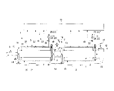
FIG. 1 is a schematic configuration diagram of an example of carbide
production
equipment according to an embodiment of the present invention.
FIG. 2 is a detailed diagram of a connecting portion between a first rotary
kiln and a
second rotary kiln in an externally heated carbonization furnace according to
the embodiment
of the present invention.
Description of Embodiments
[0024]
An externally heated carbonization furnace 2 according to an embodiment of the
present invention will be described below in detail with reference to the
accompanying
drawings. FIG. 1 is a schematic configuration diagram of an example of carbide
production
equipment 1 that is provided with the externally heated carbonization furnace
2 of the present
embodiment.
As illustrated in FIG. 1, the carbide production equipment 1 includes a screw
conveyor 3 for feeding a treated object, the externally heated carbonization
furnace 2 that
heats the treated object fed from the screw conveyor 3, and a chute 4 that
discharges the
treated object discharged from the externally heated carbonization furnace 2.
[0025]
The externally heated carbonization furnace 2 carries out a heat treatment on
the
treated object, which is a low-calorie substance, such as
CA 2928791 2018-03-01 .
CA 02928791 2016-04-26
7
sewage sludge, woody biomass, or low-grade coal, and modifies the treated
object to a carbide having a large calorific power.
The externally heated carbonization furnace 2 includes a first rotary kiln
and a second rotary kiln 7 that is connected in series to the downstream side
of the first rotary kiln 5 that heats the treated object discharged from the
first
rotary kiln 5. The first rotary kiln 5 includes an outer cylinder 10 and a
first
kiln inner cylinder 6 (a kiln shell) which rotates relatively to the outer
cylinder
and into which the treated object is fed. The second rotary kiln 7 includes
the outer cylinder 10 and a second kiln inner cylinder 8 which rotates
relatively
to the outer cylinder 10 and into which the treated object is fed.
[0026]
A combination of the first kiln inner cylinder 6 and the second kiln inner
cylinder 8 form a large cylindrical body. A length L of the cylindrical body
in
the axial direction is approximately 50 m, for example. Further, the first
kiln
inner cylinder 6, the second kiln inner cylinder 8, and the outer cylinder 10
are
installed on an installation surface F, while being inclined at a gradient of
1% to
3% with respect to the horizon.
Note that, in the description below, the axial direction of the kiln inner
cylinders 6 and 8 and the outer cylinder 10 (described below) will be simply
referred to as the axial direction.
The first rotary kiln 5 and the second rotary kiln 7 have substantially the
same configuration. The configuration of the first rotary kiln 5 will be
described below.
[0027]
The first rotary kiln 5 includes the first kiln inner cylinder 6 and the
outer cylinder 10 (a muffle) that circulates heating gas around the first kiln
inner cylinder 6. The first kiln inner cylinder 6 is supported at the upstream
side thereof by a movable support portion 11, which is movable in the axial
direction, so as to be able to rotate about the axis thereof. The first kiln
inner
cylinder 6 is supported at the downstream side thereof by a fixed support
portion 12 so as to be able to rotate about the axis thereof.
[0028]
The movable support portion 11 of the first kiln inner cylinder 6 includes
a ring-shaped frame 13 that rotatably supports the first kiln inner cylinder
6.
The ring-shaped frame 13 is rotatably supported at both sides thereof by upper
end portions of support members 14 that are provided vertically from the
installation surface F in a pivotable manner. The fixed support portion 12
also
CA 02928791 2016-04-26
8
includes the ring-shaped frame 13 that rotatably supports the first kiln inner
cylinder 6.
Note that the movable support portion 11 and the fixed support portion
12 can be installed on opposite sides to those described in the present
embodiment.
[0029]
A plurality of fins (or spirals, not illustrated in the drawings) arranged
inclining with respect to the circumferential direction are provided on the
inner
wall of the first kiln inner cylinder 6. As a result of being driven to rotate
by a
drive device 16, which will be described below, at a predetermined rotational
frequency (one to five rpm, for example), the first kiln inner cylinder 6 can
transfer the treated object, which is fed from an inlet side (the upstream
side), to
an outlet side (the downstream side) while heating the treated object. Note
that, instead of providing the fins, the first kiln inner cylinder 6 may be
rotatably supported about an axis which is slightly inclined with respect to
the
horizon, thereby transferring the treated object to the outlet side due to the
inclination and the rotation of the first kiln inner cylinder 6.
[0030]
The drive device 16 includes a gear 17 provided to the first kiln inner
cylinder 6, a drive motor 18, and a pinion gear 19 that is attached to a
rotating
shaft of the drive motor 18 and engaged with the gear 17. The drive device 16
rotates the first kiln inner cylinder 6 about the axis of the first kiln inner
cylinder 6 by transmitting the driving force of the drive motor 18 to the gear
17
so as to rotate the gear 17.
[0031]
The outer cylinder 10 is fixed to an installation area via a support
member (not illustrated), while allowing the first kiln inner cylinder 6 to
rotate
and to move in the axial direction, and securing sealing between the outer
cylinder 10 and the first kiln inner cylinder 6.
A heating gas supply pipe 20 is connected to a first end portion of the
outer cylinder 10. A second end portion positioned on the opposite side of the
first end portion of the outer cylinder 10, to which the heating gas is
supplied
from a heating gas combustion furnace 21 (a heater for suppling the heating
gas) through the heating gas supply pipe 20 is connected with a heating gas
feeding pipe 22. A heating gas amount adjustment damper 24 (a heating gas
amount adjustment device 23) and an induction fan 25 are provided in the
heating gas feeding pipe 22.
[0032]
CA 02928791 2016-04-26
9
A plurality of inspection windows 26 are provided in an upper portion of
the outer cylinder 10 at intervals in the axial direction. A non-contact type
thermometer 27 is provided in each of the inspection windows 26 to face the
outer circumferential surface of the kiln inner cylinder that rotates about
the
axis thereof. The non-contact type thermometer 27 measures a kiln shell
temperature (an iron shell temperature of the kiln inner cylinder). A
radiation
thermometer can be used as the non-contact type thermometer 27.
The externally heated carbonization furnace 2 includes a control device
15. The control device
15 and each of the non-contact-type thermometers 27
are connected so as to be able to communicate with each other. The kiln shell
temperature measured by the non-contact type thermometer 27 is input into the
control device 15. Further, the control device 15 controls the heating gas
amount adjustment device 23 and the drive device 16 on the basis of the kiln
shell temperature. A control method of the control device 15 will be described
later.
[0033]
Next, details of the ring-shaped frame 13 and a connecting portion 9
between the first rotary kiln 5 and the second rotary kiln 7 will be
described.
As illustrated in FIG. 2, the first kiln inner cylinder 6 includes a first
inner cylinder main body portion 29 formed to have a substantially constant
diameter of, for example, approximately 5 m in the axial direction, a first
conical portion 30 whose diameter is gradually reduced as the first conical
portion 30 extends further toward the downstream side in the axial direction
from the downstream side of the first kiln inner cylinder 6 so as to be formed
into a conical shape, and a first small diameter portion 31 (an upstream-side
cylindrical portion) that is formed in a cylindrical shape and extends from
the
first conical portion 30 toward the downstream side in the axial direction
while
having a substantially constant diameter.
[0034]
The second kiln inner cylinder 8 of the second rotary kiln 7 includes a
second inner cylinder main body portion 32 formed to have a substantially
constant diameter of, for example, approximately 5 m in the axial direction, a
second conical portion 33 whose diameter is gradually reduced as the second
conical portion 33 extends further toward the upstream side in the axial
direction from the upstream side of the second kiln inner cylinder 8, and a
second small diameter portion 34 (a downstream-side cylindrical portion) that
is
formed in a cylindrical shape and extends from the second conical portion 33
CA 02928791 2016-04-26
toward the upstream side in the axial direction while having a substantially
constant diameter.
The first small diameter portion 31 of the first kiln inner cylinder 6 has
an outer diameter slightly smaller than the inner diameter of the second small
diameter portion 34 of the second kiln inner cylinder 8. Specifically, the
first
small diameter portion 31 and the second small diameter portion 34 are formed
so that the first small diameter portion 31 can be inserted into the second
small
diameter portion 34.
[0035]
In the connecting portion 9 between the first rotary kiln 5 and the second
rotary kiln 7, the first small diameter portion 31 is inserted into the second
small diameter portion 34. Specifically, the first small diameter portion 31
is
inserted into the inner circumferential side of the second small diameter
portion
34 in the radial direction. The first small diameter portion 31 and the second
small diameter portion 34 are disposed so that the central axes thereof are
aligned on the same straight line. Accordingly, the first small diameter
portion 31 and the second small diameter portion 34 are disposed so as to
partially overlap with each other in the axial direction. Such a structure
makes
it possible to smoothly transfer the treated object from the first kiln inner
cylinder 6 to the second kiln inner cylinder 8.
[0036]
The ring-shaped frames 13 are provided on the outer circumferential side
of the conical portions 30 and 33 or the small diameter portions 31 and 34.
Each of the ring-shaped frames 13 includes a frame main body portion 36 that
extends in the circumferential direction, and a bearing retaining portion 37
that
protrudes toward the kiln inner cylinder 6 or 8 on the inner circumferential
side
of the frame main body portion 36. The bearing retaining portion 37 extends
in the circumferential direction and retains a bearing 38 on the outer
circumferential side of the bearing retaining portion 37. The bearings 38
rotatably support the kiln inner cylinders 6 and 8 via ring-shaped protrusions
40
that protrude from end wall portions 39 of the kiln inner cylinder 6 and 8 in
the
axial direction.
Specifically, the kiln inner cylinders 6 and 8 are rotatably supported via
the ring-shaped frames 13. Each of the ring-shaped frames 13 is supported by
the support member 14 (see FIG. I) that is provided vertically from the
installation surface F.
[0037]
Next, a sealing mechanism in the connecting portion 9 will be described.
CA 02928791 2016-04-26
11
The connecting portion 9 between the first rotary kiln 5 and the second
rotary kiln 7 includes sealing plates 41 that protrude from the outer
circumferential surface of the conical portions 30 and 33 or the small
diameter
portions 31 and 34 of the kiln inner cylinders 6 and 8 toward the outer
circumferential side in the radial direction and extend in the circumferential
direction; ring-shaped presser plates 42 each attached to the ring-shaped
frame
13; an expansion member 43 provided so as to cover the outer circumferential
side of the small diameter portions 31 and 34; and gland packings 44 each
disposed between the sealing plate 41 and the presser plate 42.
[0038]
The sealing plates 41 provided to the kiln inner cylinders 6 and 8 rotate
together with the kiln inner cylinders 6 and 8. The gland packings 44 are
fixed
to the sealing plates 41 and rotate together with the sealing plates 41. In
this
case, as a result of the gland packings 44 sliding against sliding surfaces of
the
presser plates 42, sealing is obtained. The expansion member 43 is formed in
a bellows and substantially cylindrical shape. The bellows-shaped portion of
the expansion member 43 is expandable in the axial direction.
[0039]
Carbon fiber gland packings can be adopted as the gland packings 44, for
example. Because the gland packings 44 formed by weaving carbon fibers
have an extremely small friction coefficient, the sealing performance can be
maintained for a long period of time.
Note that, as illustrated in FIG. 1, in a connecting part between the
movable support portion 11 of the first rotary kiln 5 and the screw conveyor
3,
an expansion member 45 is provided that absorbs displacement of the movable
support portion 11 in the axial direction.
[0040]
Next, the control device 15 of the externally heated carbonization
furnace 2 according to the present embodiment will be described. The control
device 15 controls the amount of heating gas and the rotational frequency of
the
kiln inner cylinder on the basis of the kiln shell temperature detected by
each of
the plurality of non-contact type thermometers 27. The kiln shell temperature
detected by each of the plurality of non-contact type thermometers 27 is
transmitted to the control device 15.
[0041]
Because the kiln shell temperature is a temperature of the section that
directly comes into contact with the treated object inside the kiln inner
cylinder,
the kiln shell temperature is highly correlated with the thermal decomposition
CA 02928791 2016-04-26
12
temperature of the treated object, and thus favorably reflects the heating
condition. Therefore, as a result of performing the temperature control on the
basis of the kiln shell temperature, it becomes possible to control the
heating
temperature in a stable manner. Particularly, the kiln shell temperature
fluctuates depending on the moisture content of the treated object. When the
moisture content of the treated object increases, evaporation of the moisture
increases. As a result, the kiln shell temperature decreases. The control
device 15 of the present embodiment uses the kiln shell temperature to
estimate
the moisture content of the treated object.
[0042]
Because the externally heated carbonization furnace 2 of the present
embodiment includes two of the rotary kilns 5 and 7 on the upstream side and
the downstream side thereof, the control device 15 can individually control
the
amounts of heating gas and rotational frequencies of the kiln inner cylinders
of
the rotary kilns 5 and 7.
[0043]
Here, in the externally heated carbonization furnace 2 of the present
embodiment, the kiln inner cylinder is divided into the upstream side and the
downstream side. The first kiln inner cylinder 6 functions as an evaporation
zone in which the moisture in the treated object is evaporated, and the second
kiln inner cylinder 8 functions as a carbonization zone in which the treated
object is carbonized.
The control device 15 adjusts the amount of heating gas by controlling
the degree of opening of the heating gas amount adjustment damper 24 and the
rotational frequency of the induction fan 25, so that the kiln shell
temperature
measured by each of the plurality of non-contact type thermometers 27 is
maintained within a predetermined temperature range.
When the kiln shell temperature cannot be maintained within the
predetermined temperature range even by adjusting the amount of heating gas,
the evaporation of the treated object is accelerated by increasing the
rotational
frequency (increasing the rotation speed) of the first kiln inner cylinder 6.
The
kiln shell temperature decreases as a result of the evaporation from the
treated
object increasing.
[0044]
As described above, the externally heated carbonization furnace 2 of the
present embodiment is divided into the rotary kiln (kiln inner cylinder) that
functions as the evaporation zone and the rotary kiln (kiln inner cylinder)
that
functions as the carbonization zone. Thus, even when the rotational frequency
CA 02928791 2016-04-26
13
of the first kiln inner cylinder 6 of the first rotary kiln 5 is increased, it
is
possible to maintain the rotational frequency of the second kiln inner
cylinder 8
of the second rotary kiln 7 as it is. Specifically, even when the rotational
frequency of the first kiln inner cylinder 6 is increased so as to accelerate
the
evaporation of the moisture from the treated object, it is possible to
maintain
the rotational frequency of the second kiln inner cylinder 8, in which
carbonization processing is performed.
[0045]
In other words, even when the moisture content of the treated object is
high, it is possible to cause the treated object, which is fed into the
carbonization zone (the second kiln inner cylinder 8), to have an appropriate
level of moisture content by accelerating evaporation processing performed in
the evaporation zone (the first kiln inner cylinder 6).
Further, in a case in which an externally heated carbonization furnace
includes only one kiln inner cylinder, when the evaporation zone becomes
longer, the carbonization zone becomes shorter accordingly. However, by
providing the evaporation zone and the carbonization zone independently from
each other, and also by adjusting the degree of evaporation by controlling the
rotational frequency of the kiln inner cylinder as well as the amount of
heating
gas, the degree of carbonization in the carbonization zone is not affected.
[0046]
According to the above-described embodiment, controlling the
respective rotational frequencies of the kiln inner cylinders 6 and 8 in the
two
rotary kilns 5 and 7 according to the moisture content of the treated object,
a
stable production of carbide becomes possible even when the moisture content
of the treated object to be fed fluctuates. Specifically, it is possible to
maintain the rotational frequency of the second kiln inner cylinder 8, while
changing the rotational frequency of the first kiln inner cylinder 6.
More specifically, in a case when the moisture content of the treated
object becomes high, and it is thus not possible to achieve an appropriate
level
of evaporation only by adjusting the amount of heating gas in the first kiln
inner
cylinder 6, which functions as the evaporation zone, it is possible to
increase
the rotational frequency (increase the rotation speed) of the first kiln inner
cylinder 6 by using the control device l 5. Accordingly, even when the
moisture content of the treated object becomes high, it is possible to reduce
the
moisture content of the treated object to an appropriate level in the
evaporation
zone.
[0047]
CA 02928791 2016-04-26
14
Further, as a result of having a structure in which two kiln inner
cylinders are connected to each other in series, even when a large rotary kiln
is
used, it is possible to expand the heat transfer surface area, while avoiding
an
impact on the structural strength of the rotary kiln.
[0048]
Further, as a result of estimating the moisture content of the treated
object using the kiln shell temperature, it is possible to ascertain the
fluctuations in the moisture content of the treated object, without directly
measuring the moisture content of the treated object.
Furthermore, as a result of controlling the rotational frequency of the
kiln inner cylinder as well as adjusting the amount of heating gas, it is
possible
to handle significant fluctuations in the moisture content. Specifically, even
when the responsiveness of the temperature control is not sufficient when only
adjusting the amount of heating gas, the temperature control becomes possible.
[0049]
Further, in the connecting portion 9 between the first kiln inner cylinder
6 and the second kiln inner cylinder 8, the internal space of the first kiln
inner
cylinder 6 and the internal space of the second kiln inner cylinder 8 directly
communicate with each other. As a result, it is possible to minimize a section
that is not heated by the heating gas.
Further, in the connecting portion 9 between the first kiln inner cylinder
6 and the second kiln inner cylinder 8, the expansion member 43 is provided
that causes the kiln inner cylinders 6 and 8 to be tightly sealed with each
other.
As a result, air is inhibited from flowing into the kiln inner cylinders 6 and
8,
and also, the thermal expansion of the kiln inner cylinders 6 and 8 can be
absorbed by the expansion member 43.
Furthermore, as a result of the one end portion of each of the kiln inner
cylinders 6 and 8 being supported by the movable support portion 11, which is
movable in the axial direction, the thermal expansion of the kiln inner
cylinders
6 and 8 can be absorbed. Specifically, even when the kiln inner cylinders 6
and 8 are maintained at high temperatures ranging from 300 C to 700 C,
sealability of a sliding section of the connecting portion 9 can be
maintained.
[0050]
The embodiment of the present invention has been described above in
detail with reference to the accompanying drawings. However, each of the
configurations described in each of the embodiments, combinations thereof, and
the like are merely examples, and it is possible to add a configuration, or
omit,
replace, or modify the above-described configuration without departing from
CA 02928791 2016-04-26
the spirit of the present invention. Further, the present invention is not
limited
by the above-described embodiment, but only limited by the scope of the
claims.
For example, in the externally heated carbonization furnace 2 of the
present embodiment, the amount of heating gas and the rotational frequency of
the kiln inner cylinder are controlled on the basis of the kiln shell
temperature,
but the control method is not limited to this example. For example, the
present invention may have a configuration in which a thermometer is provided
inside the kiln inner cylinder, and the temperature of the treated object may
be
directly measured by the thermometer.
[0051]
Further, in the externally heated carbonization furnace 2 of the present
embodiment, the kiln inner cylinder is divided into the first kiln inner
cylinder 6
on the upstream side and the second kiln inner cylinder 8 on the downstream
side. However, the present invention is not limited to this example, and the
kiln inner cylinder may be divided into three or more parts. Specifically, a
configuration may be adopted in which three or more kiln inner cylinders are
connected with each other.
Further, the number of the non-contact type thermometers is also not
limited to three, but the installation number can be chosen as desired.
Industrial Applicability
[0052]
According to this externally heated carbonization furnace, by controlling
the rotational frequency of the kiln inner cylinder in each of the plurality
of
rotary kilns according to the moisture content of the treated object, it is
possible
to stably produce carbide even when the moisture content of the treated object
to be fed fluctuates.
Reference Signs List
[0053]
1 Carbide production equipment
2 Externally heated carbonization furnace
3 Screw conveyor
4 Chute
5 First rotary kiln
6 First kiln inner cylinder
7 Second rotary kiln
CA 02928791 2016-04-26
16
8 Second kiln inner cylinder
9 Connecting portion
Outer cylinder
11 Movable support portion
12 Fixed support portion
13 Ring-shaped frame
14 Support member
Control device
16 Drive device
17 Gear
18 Drive motor
19 Pinion gear
Heating gas supply pipe
21 Heating gas furnace (heater)
22 Heating gas feeding pipe
23 Heating gas amount adjustment device
24 Heating gas amount adjustment damper
Induction fan
26 Inspection window
27 Non-contact type thermometer
29 First inner cylinder main body portion
First conical portion
31 First small diameter portion (Upstream-side cylindrical portion)
32 Second inner cylinder main body portion
33 Second conical portion
34 Second small diameter portion (Downstream-side cylindrical portion)
36 Frame main body portion
37 Bearing retaining portion
38 Bearing
39 End wall portion
Ring-shaped protrusion
41 Sealing plate
42 Presser plate
43 Expansion member
44 Gland packing
F Installation surface