Note: Descriptions are shown in the official language in which they were submitted.
CA 02929245 2016-04-29
WO 2015/088693
PCT/US2014/065137
METHOD AND APPARATUS FOR OPTIMIZED PRESENTATION OF
COMPLEX MAPS
FIELD
100011 Aspects of the disclosure relate to electronic maps, and particularly
to the
automatic selection of viewing parameters such as virtual camera placement in
presentation of multi-level or three-dimensional maps.
BACKGROUND
100021 As mobile electronic devices capable of displaying local and building
level
maps become more prevalent, and location services become more common, mobile
devices which are using location services may have access to map information
which
represents three dimensions. Complex venue sites, such as university
buildings,
business offices and shopping malls, can have complex layouts and become
daunting to
navigate for a user. Geometric structures of points of interests (130Is) on
different floors
make these maps difficult to use. This problem is further exacerbated by the
small
screen of many mobile devices. Improved systems and methods for presenting
three-
dimensional data and maps may thus be desirable.
BRIEF SUMMARY
100031 Embodiments described herein include a method for optimized map
presentation. For example, one embodiment may be a method comprising
receiving, at
a mobile device, a first set of placement data associated with a first object;
receiving, at
the mobile device, a second set of placement data associated with a second
object; and
determining, at the mobile device, overlap between a representation of the
first object
and the second object in a rendering of an image comprising the representation
of the
first object and the second object, using a set of viewing parameters, the
first set of
placement data and the second set of placement data. The method may then
further
comprise adjusting, at the mobile device, the set of viewing parameters to
reduce
overlap between the representation of the first object and the second object
in the
rendering of the image.
100041 Such a method may further function where the placement data comprises
map
data or where the first object comprises a first level of a location and the
second object
-1-
CA 02929245 2016-04-29
WO 2015/088693
PCT/US2014/065137
comprises a second level of the location. Such a method may further function
where
adjusting the set of viewing parameters comprises at least one of: changing a
distance
between a viewing position and the objects; changing a tilt associated with
the viewing
position; changing a distance between the first and second object; or changing
a
placement of the viewing position; or any combination thereof. Such a method
may
further function where determining overlap between the first object and the
second
object comprises rendering the image of the first object and the second object
and
determining that a ratio of (a) overlapping pixels between the first object
and the second
object to (b) a total number of pixels is beyond a threshold.
100051 Such a method may further function where determining the overlap
between
the first object and the second object is performed in response to a change in
a
placement of a viewing position. Such a method may further function where the
placement of the viewing position is changed by at least one of: an input
received from
a user, a context of the user, or a search query received from the user, or
any
combination of the above.
100061 Such a method may further comprise determining a back-facing boundary
associated with the first object and the second object; and shading a region
between the
back-facing boundary of the first object and the second object.
100071 Another embodiment may be a device with optimized functionality for map
presentation, the device comprising: a memory; a display output; and a
processor
coupled to the memory and the display output, wherein the memory comprises a
3D
display management module that, when executed by the processor, causes the
processor
to perform certain functions. A.s part of such functions, the processor may:
receive a
first set of placement data associated with a first object; receive a second
set of
placement data associated with a second object; determine overlap between a
representation of the first object and the second object in a rendering of an
image
comprising the representation of the first object and the second object, using
a set of
viewing parameters, the first set of placement data and the second set of
placement data;
and adjust the set of viewing parameters to reduce overlap between the
representation of
the first object and the second object in the rendering of the image. The
device may
further comprise a display output, wherein the processor further outputs an
adjusted
rendering of the image to the display output for display.
-2-
CA 02929245 2016-04-29
WO 2015/088693
PCT/US2014/065137
100081 In additional embodiments, such a device may function where the
placement
data comprises map data or where the first object comprises a first level of a
location
and the second object comprises a second level of the location. Additional
embodiments may function where adjusting the set of viewing parameters
comprises
changing a distance between a viewing position and the objects, changing a
tilt
associated with the viewing position, changing a distance between the first
and second
object, and changing a placement of the viewing position.
100091 Such a device may further comprise an antenna and a transceiver coupled
to
the antenna and the processor, wherein the first set of placement data and the
second set
of placement data is received at the antenna and communicated to the memory
via the
transceiver prior to the processor receiving the first set of placement data
and the second
set of placement data.
100101 Another embodiment may be a device with optimized functionality for map
presentation, the device comprising: means for receiving, at a mobile device,
a first set
of placement data associated with a first object; means for receiving, at the
mobile
device, a second set of placement data associated with a second object; means
for
determining, at the mobile device, overlap between a representation of the
first object
and the second object in a rendering of an image comprising the representation
of the
first object and the second object, using a set of viewing parameters, the
first set of
placement data and the second set of placement data; and means for adjusting,
at the
mobile device, the set of viewing parameters to reduce overlap between the
representation of the first object and the second object in the rendering of
the image.
NOM Another embodiment may be a device where the placement data
comprises
map data and wherein the first object comprises a first level of a location
and the second
object comprises a second level of the location. Another embodiment may be a
device
wherein means for adjusting the set of viewing parameters comprises means fur
changing a distance between a viewing position and the objects, changing a
tilt
associated with the viewing position, changing a distance between the first
and second
object, and changing a placement of the viewing position.
100121 Another embodiment may be a device further comprising means for
determining a back-facing boundary associated with the first object and the
second
-3-
CA 02929245 2016-04-29
WO 2015/088693
PCT/US2014/065137
object; and means for shading a region between the back-facing boundary of the
first
object and the second object.
100131 Another embodiment may be a non-transitory computer-readable medium
comprising computer-readable instructions for map presentation that, when
executed by
a processor, cause a mobile device to perform a method for optimized display
of maps,
the method comprising: receiving, at the mobile device, a first set of
placement data
associated with a first object; receiving, at the mobile device, a second set
of placement
data associated with a second object; determining, at the mobile device,
overlap
between a representation of the first object and the second object in a
rendering of an
image comprising the representation of the first object and the second object,
using a set
of viewing parameters, the first set of placement data and the second set of
placement
data; and adjusting, at the mobile device, the set of viewing parameters to
reduce
overlap between the representation of the first object and the second object
in the
rendering of the image.
100141 An additional embodiment may function where adjusting the set of
viewing
parameters comprises changing a distance between a viewing position and the
objects,
changing a tilt associated with the viewing position, changing a distance
between the
first and second object, and changing a placement of the viewing position.
100151 An additional embodiment may function where determining overlap between
the first object and the second object comprises rendering an image of the
first object
and the second object and determining that a ratio of overlapping pixels
between the
first object and the second object to a total number of pixels are beyond a
threshold.
100161 An additional embodiment may function where determining the overlap
between the first object and the second object is performed in response to a
change in a
placement of a viewing position; and wherein the placement of the viewing
position is
changed by at least one of: an input received a user, context of the user, or
a search
query received from the user, or any combination of the above.
-4-
CA 02929245 2016-04-29
WO 2015/088693
PCT/US2014/065137
BRIEF DESCRIPTION OF THE DRAWINGS
100171 A further understanding of the nature and advantages of various
embodiments
may be realized by reference to the following figures. In the appended
figures, similar
components or features may have the same reference label. Further, various
components of the same type may be distinguished by following the reference
label by a
dash and a second label that distinguishes among the similar components. If
only the
first reference label is used in the specification, the description is
applicable to any one
of the similar components having the same first reference label irrespective
of the
second reference label.
100181 FIG. 1 describes map or object data according to one embodiment;
100191 FIG. 2A describes map or object data according to one embodiment;
100201 FIG. 2B describes map or object data according to one embodiment;
100211 FIG. 3 describes map or object data according to one embodiment;
100221 FIG. 4 is one example of a mobile device for use with an embodiment;
100231 FIG. 5 describes map or object data according to one embodiment;
[0024] FIG. 6 illustrates certain viewing parameters according to some
embodiments;
[0025] FIG. 7 describes a method for presenting map data in accordance with
one
embodiment;
100261 FIG. 8 describes a method for presenting map data in accordance with
one
embodiment;
[0027] FIG. 9 is one implementation of a computer device according to certain
embodiments; and
100281 FIG. 10 is one implementation of a networked computer system according
to
certain embodiments.
-5-
CA 02929245 2016-04-29
WO 2015/088693
PCT/US2014/065137
DETAILED DESCRIPTION
100291 Embodiments described herein include systems, methods, devices, and
computer-readable media for improved presentation of object and map data.
Certain
embodiments may be particularly directed to mobile electronic devices which
may
display map data. It will be understood, however, that a wide variety of other
implementations will be available in accordance with the embodiments described
herein.
100301 In one example, a mobile device may have map inthrmation for a two-
story
building, with the map for each floor in a two-dimensional format. A top down
view of
both floors together would either block most of the lower floor if the maps
are opaque,
or cause confusion as to what information was associated with which floor if
the maps
are transparent. Embodiments described herein may change a viewing angle and a
relative distance between the maps without distorting the position between
points above
and below each other in the map information of each floor, in order to reduce
the
overlap between the maps as output on the display.
10031.1 In certain embodiments, techniques described herein propose a method
and
apparatus for adjusting the viewing parameters associated with a viewing
position (e.g.,
a virtual camera in rendering software such as OpenGL) to reduce the
overlapping of
point of interest (POI) information in three-dimensional (3D) display for
indoor maps.
The viewing parameters associated with a viewing position can be optimized for
displaying complex venues in a default view, given the POI information and the
geometry of these POIs. In one aspect, the virtual camera discussed herein is
a camera
library function used in rendering software, such as OpenGL, that simulates
the
perspective of a user viewing the device display of the mobile device. In one
embodiment, for example, viewing parameters for such a rendering may be
encapsulated in a 4x4 matrix for rendering in 3D rendering systems (e.g.,
OpenGL and
DirectX). In other embodiments, other matrix sizes or rendering methods may be
used.
In another aspect, the 3D image discussed herein is a simulated 3D image
displayed in
two dimensions on the mobile display.
100321 A display in a mobile device is typically a two-dimensional display. In
the
embodiments described herein, such a two-dimensional display may be used for
-6-
CA 02929245 2016-04-29
WO 2015/088693
PCT/US2014/065137
presenting three-dimensional information. Because of this, additional
considerations
beyond what is presented in a top down two-dimensional map may be helpful in
providing information to a viewer. The information in FIGs. 1-3 is presented
from
multiple and differing viewing perspectives. Changes are such that a viewing
perspective or virtual "camera" position may be selected by user input or
automatically
selected by the mobile device in order to provide the three-dimensional
information to a
viewer in an acceptably understandable format. Viewing parameters that set the
viewing perspective or virtual camera position may have associated threshold
values,
and as is described for the various embodiments herein, changes in the virtual
camera
position may be made to create an output image that falls within the threshold
values of
the viewing parameters. FIGs. 1-3 detail aspects of such viewing parameters.
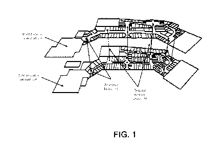
100331 FIG. 1, for example, shows map object information for a first level of
a
location 110 and a second level of a location 120. The term "location" as
referred to
herein may refer to a building, an environment, an area, an open air venue, a
stadium, a
park, or any similar such space which may include multiple levels. The
information of
FIG. 1 may, for example, be information output by a display of a mobile
electronic
device. Reference points 131 indicate a point in each level that is in the
same position
at a different height, in order to provide information to a viewer about the
relationship
between the levels. The distance between levels 130 is not presented to scale,
but is
instead set to optimize the display of the multiple levels according to
predetermined
preferences. This distance between levels 130 may be optimized to reduce
overlap, to
enable certain viewing elevations, or as an optimized viewing parameter along
with any
number of other viewing parameters.
100341 FIG. 2A shows another perspective of the levels from FIG. 1, including
the
first level of a location 110 and the second level of a location 120. FIG. 2A
may be
considered the combination of two top down maps which are widely available for
many
locations. The perspective of FIG. 2A includes a significant amount of overlap
140a
when using such top down maps to show multiple levels of the same top down
space.
FIG. 2A thus illustrates rendering of an image using image data for two levels
of a
multi-level building without using the optimization techniques described
herein, but
may be considered a starting point from initial top down map information. As
shown in
FIG. 2, the data associated with the two levels overlaps significantly and
does not
-7-
CA 02929245 2016-04-29
WO 2015/088693
PCT/US2014/065137
provide a useful view of the data for the user to navigate the venue. For
complex venue
maps, which may be a shopping mall that includes a large number of stores or
an
apartment complex with a large number of units, such a view can be very
overwhelming
for the user. While this view may be typical when only a single level is being
presented
in a display, in order to present multiple levels, a different viewing angle
provides
reduced overlap and less confusion. Also, in FIG. 2A, the distance between
levels 130
is not visible since the reference points 131 are essentially on top of each
other.
[0035] In FIG. 2B, then another view of the first level of the location 110
and the
second level of the location 120 are shown. In this view, there is still a
certain amount
of overlap, shown as overlap 140b. This overlap is less than the overlap 140a
of FIG.
2A, and any loss of information or confusion due to overlap 140b is minor.
FIG. 2B
thus illustrates rendering of an image using the same image data for two
levels of a
multi-level building discussed in FIG. 2A, using techniques described herein.
As shown
in FIG. 2B, by detecting overlap of the image data and adjusting viewing
parameters of
the virtual camera, the two levels of a multi-level building may be displayed
in a
manner that provides the user with useful navigation information that
minimizes overlap
between the two levels of the multi-level building. This enables top down map
views to
be transformed in a way that enable three-dimensional views of a location that
may be
automatically customized to typical or user-selected preference thresholds.
100361 FIG. 3 describes a further enhanced embodiment of information that may
be
displayed. After an acceptable view is selected along with any associated
viewing
parameters, such as distance between levels, such additional enhancements may
be added.
FIG. 3 includes a representation of first object 310 and a representation of
second object
320 as part of information to be displayed on, for example, a mobile device.
These
objects have been analyzed and set as having an acceptable amount of overlap
and
positioning. Just as in FIG. 1, FIG. 3 includes distance between objects 330.
The image
of FIG. 3 also includes shading to provide additional three-dimensional
information to a
viewer. In particular, shading in region 342 between a back-facing boundary of
the first
object 312 and a back-facing boundary of the second object 322. In certain
embodiments,
once viewing parameters are set for presentation of the three-dimensional
objects, shading
in region 342 may be added to the display to provide additional clarity in the
presentation
of the three-dimensional information from a two-dimensional display screen of
a mobile
-8-
CA 02929245 2016-04-29
WO 2015/088693
PCT/US2014/065137
device. FIG. 3 thus illustrates a rendering of the data associated with the
two floors of the
multi-floor building. As shown, the data may be rendered to further enhance
the 3D
effect created from placing two levels in the same rendered image, and
facilitate easy
viewing of the navigation data for the user. One implementation may include
determining
the back-facing boundaries associated with the two floors of the multi-floor
building,
connecting the boundary walls and shading those walls with one color, and
shading the
top floor with a different hue than the boundary wall. In various other
embodiments,
additional color enhancements may be made to enable distinction between the
level
information being presented in the single image rendering. For example,
different levels
may have slight color differences in shading.
100371 FIG. 4 now describes one implementation of a mobile device 400
according to
certain embodiments. Mobile device 400 of FIG. 4 may be used to output an
image
similar to the images of FIGs. 1-3 using a 3D display management module 421.
Mobile
device 400 may also implement processing steps to transform an image such as
the
image of FIG. 2A into the image of FIG. 2B using a processor 410 along with
computer-readable instructions that may be stored in memory 420. 3D display
management module 421 may include a set of thresholds for acceptable
characteristics
of an output image, as well as processes for adjusting viewing parameters and
measuring image characteristics to achieve the acceptable characteristics for
an output
image. Additional details of such processes which may be initiated and managed
by 3D
display management module 421 are described below with respect to FIGs. 5-8.
100381 In certain embodiments, where a device such as mobile device 400 is to
display a three-dimensional output, one or more relevant pieces of image,
object, or
map level information may be received from links 416 or 446 and then stored in
memory 420, either as part of an application 424, or in a non-transitory
storage of
memory 420. The information may then be merged and/or adjusted with a device-
selected virtual camera perspective by 3D display management module 421 before
being presented to a user on a display output 403.
10039] In the embodiment shown at FIG. 4, mobile device 400 includes processor
410
configured to execute instructions for performing operations at a number of
components
and can be, for example, a general-purpose processor or microprocessor
suitable for
implementation within a portable electronic device. Processor 410 is
communicatively
-9-
CA 02929245 2016-04-29
WO 2015/088693
PCT/US2014/065137
coupled with a plurality of components within mobile device 400. To realize
this
communicative coupling, processor 410 may communicate with the other
illustrated
components across a bus 440. Bus 440 can be any subsystem adapted to transfer
data
within mobile device 400. Bus 440 can be a plurality of computer buses and
include
additional circuitry to transfer data.
100401 Memory 420 may be coupled to processor 410. In some embodiments,
memory 420 offers both short-term and long-term storage and may in fact be
divided
into several units. Memory 420 may be volatile, such as static random access
memory
(SRAM) and/or dynamic random access memory (DRAM), and/or non-volatile, such
as
read-only memory (ROM), flash memory, and the like. Furthermore, memory 420
can
include removable storage devices, such as secure digital (SD) cards. Thus,
memory
420 provides storage of computer-readable instructions, data structures,
program
modules, and other data for mobile device 400. In some embodiments, memory 420
may be distributed into different hardware modules 401.
100411 In some embodiments, memory 420 stores a plurality of application
modules,
which may be any number of applications 424. Application modules contain
particular
instructions to be executed by processor 410. In alternative embodiments,
other
hardware modules 401 may additionally execute certain applications 424 or
parts of
applications 424. In certain embodiments, memory 420 may additionally include
secure
memory, which may include additional security controls to prevent copying or
other
unauthorized access to secure information such as private or secure map
information or
private placement data which may be part of level, map, or object information.
100421 In some embodiments, memory 420 includes an operating system 423.
Operating system 423 may be operable to initiate the execution of the
instructions
provided by application modules and/or manage other hardware modules 401 as
well as
interfaces with communication modules which may use WAN wireless transceiver
412
and LAN wireless transceiver 442 to receive information from link 416 via
antenna 414
and/or link 446 via antenna 444, respectively. Operating system 423 may be
adapted to
perform other operations across the components of mobile device 4(X) including
threading, resource management, data storage control and other similar
functionality.
-10-
CA 02929245 2016-04-29
WO 2015/088693
PCT/US2014/065137
[0043] In some embodiments, mobile device 400 includes a plurality of other
hardware modules 401. Each of other hardware modules 401 is a physical module
within mobile device 400. However, while each of hardware modules 401 is
permanently configured as a structure, a respective one of hardware modules
401 may
be temporarily configured to perform specific functions or temporarily
activated. A
common example is an application module that may program a camera module
(i.e.,
hardware module) for shutter release and image capture. A respective one of
hardware
modules 401 can be, for example, an accelerometer, a Wi-Fi transceiver, a
satellite
navigation system receiver (e.g., a GPS module), a pressure module, a
temperature
module, an audio output and/or input module (e.g., a microphone), a camera
module, a
proximity sensor, an alternate line service (ALS) module, a capacitive touch
sensor, a
near field communication (NFC) module, a Bluetooth transceiver, a cellular
transceiver,
a magnetometer, a gyroscope, an inertial sensor (e.g., a module that combines
an
accelerometer and a gyroscope), an ambient light sensor, a relative humidity
sensor, or
any other similar module operable to provide sensory output and/or receive
sensory
input. In some embodiments, one or more functions of the hardware modules 401
may
be implemented in software.
100441 Mobile device 400 may include a component such as a wireless
communication module which may integrate antenna 414 and wireless transceiver
412
with any other hardware, firmware, or software necessary for wireless
communications.
Such a wireless communication module may be configured to receive signals from
various devices such data sources via networks and access points. In addition
to other
hardware modules 401 and applications 424 in memory 420, mobile device 400 may
have a display output 403 and a user input module 404. Display output 403
graphically
presents information from mobile device 400 to the user. This information may
be
derived from one or more applications 424, one or more hardware modules 401, a
combination thereof, or any other suitable means for resolving graphical
content for the
user (e.g., by operating system 423). Display output 403 can be liquid crystal
display
(LCD) technology, light-emitting polymer display (LPD) technology, or some
other
display technology. In some embodiments, display output 403 is a capacitive or
resistive touch screen and may be sensitive to haptic and/or tactile contact
with a user.
In such embodiments, the display output 403 can comprise a multi-touch-
sensitive
-11-
CA 02929245 2016-04-29
WO 2015/088693
PCT/US2014/065137
display. Display output 403 may then be used to display the three-dimensional
map
information as set by 3D display management module 421.
100451 Additional embodiments of a mobile device may further comprise various
portions of computing devices as are detailed below with respect to FIG. 9 and
networks
as detailed in FIG. 10.
100461 FIGs. 5 and 6 show another example of an image that may be output on a
device such as mobile device 400. FIG. 5 shows placement data, which may be a
representation of an object or may be map level data indicating the placement
of walls,
doors, or other location details. FIG. 6 shows one example of viewing
parameters
which may be used to select a perspective that creates the final image to be
output, such
as the image of FIG. 5.
100471 FIGs. 5 and 6, as shown, both include first placement data 510, second
placement data 520, and third placement data 530. FIG. 5 further includes
overlap 502,
which is an overlap between first placement data 510 and second placement data
520;
object distance 506; and object distance 508. FIG. 5 also shows overlap 504,
which is
an overlap between second placement data 520 and third placement data 530.
FIG. 6
additionally shows view 500, viewing distance 525, viewing elevation 540, and
viewing
angle 550.
100481 Object distance 506 is the distance between third placement data 530
and
second placement data 520, and object distance 508 is the distance between
second
placement data 520 and first placement data 510. While placement data as shown
in the
various figures herein are shown as parallel planes, in other embodiments, the
placement data may be three-dimensional, with the distance set by
corresponding points
between different levels, such as a distance between two reference points 131.
100491 The image of placement data in FIG. 5 may be considered the image taken
from view 500. Viewing parameters may be considered object distances 506 and
508,
viewing distance 525, viewing angle 550, and viewing elevation 540. Additional
viewing parameters may include, for example, the tilt at view 500, which
refers to the
facing angle over view 500 even when viewing elevation 540, viewing distance
525,
and viewing angle 550 stay the same. Such a viewing tilt may have multiple
components, including horizontal and vertical tilt, as well as roll as the
view spins while
-12-
CA 02929245 2016-04-29
WO 2015/088693
PCT/US2014/065137
focused along one line. In various other embodiments, other coordinate systems
or
structures may be used to define such viewing parameters, including any
parameter that
may impact characteristics of the final output to be displayed on a device.
Field of view
characteristics associated with the virtual camera or viewing perspective may
also be
considered viewing parameters.
100501 In certain embodiments, a characteristic may be a ratio of placement
data area
to overlap area. If viewing angle 550 is increased, the placement data area
will
increase, but the overlap area will increase more quickly than. the placement
data area.
The image of FIG. 2A is an example of overlap at a large viewing elevation.
Similarly,
if the viewing distance 525 is decreased with other parameters held constant,
the
placement area shown on a device display will increase, but the area of
overlap will
increase proportionately. Decreasing the viewing angle 550 or increasing
object
distances 506 and 508 may decrease overlap, but may make placement data
difficult to
view.
100511 A system may thus have a set of output parameters that it may use to
target an
acceptable output. For example, one set of output parameters may be a minimum
ratio
of visible placement data area to device display area, and a maximum overlap
to total
placement data ratio, were the visible placement data is the visible area from
view 500.
In FIG. 5, for example, the entirety of third placement data 530 is visible
placement
data, but only the bottom part of first placement data 510 is visible
placement data,
because the rest is covered by overlap 502.
10052] FIG. 7, then, describes one embodiment of a method for optimized
virtual
camera or view placement for displaying complex venue maps on mobile devices.
S702
involves receiving, at a mobile device, a first set of placement data
associated with a
first object. In certain embodiments, this may involve a wireless
communication when
the mobile device is on site at a location described by the set of placement
data. In
other embodiments, this may be a database of many different places that is
downloaded
to a mobile device. In further embodiments, a wired connection may be used to
receive
this information at the mobile device. S704 then further involves receiving,
at the
mobile device, a second set of placement data associated with a second object.
This
placement data may be received in the same way as the first set of placement
data, or
may be received in a different way. These two sets of placement data may be
received
-13-
CA 02929245 2016-04-29
WO 2015/088693
PCT/US2014/065137
at the same time as part of the same communication or parallel communications,
or may
be received at widely differing times as part of different communications.
100531 S706 then involves determining, at the mobile device, overlap between a
representation of the first object and the second object in a rendering of an
image
comprising the representation of the first object and the second object, using
a set of
viewing parameters, the first set of placement data and the second set of
placement data.
Then, step S708 includes adjusting, at the mobile device, the set of viewing
parameters
to reduce overlap between the representation of the first object and the
second object in
the rendering of the image.
100541 Detecting an overlap between the data associated with the first
representation
and the second representation may include performing an overlapping test. In
one
implementation, the overlapping test may include rendering an image of the
first object
from the first representation and the second object from the second
representation and
determining that the ratio of overlapping pixels between the first floor and
the second
floor is beyond a threshold. The overlapping test may be performed in response
to a
change in the placement of the virtual camera or view. The placement of the
virtual
camera or view may be changed in response to input received by a user, the
context of
the user, or a search query received from the user. For example, in mobile
device 400
as described by FIG. 4, a 3D display management module 421 may have a user
interface
that accepts inputs from a user input module 404 to set thresholds customized
for
display output 403. This may include ratio and pixel settings specific to
display output
403. It also may include preferences related to certain viewing parameters,
such as a
maximum or minimum preferred viewing angle.
100551 In further embodiments, such a ratio may only be for a portion of a
map. For
example, all clothing stores (based on a user's search query) in a certain
floor can be
treated as a single object in computing the overlap ratio. The method adjusts
the virtual
camera placement such that the clothing stores in two floors have less overlap
in the 3D
view. Thus, when a user is only focusing on viewing a map of clothing stores,
an overlap
analysis may similarly only focus on clothing stores. Similar analysis and
virtual camera
placement may be done for any searchable subset of map areas for any number of
levels.
Such partial map analysis may be set to automatically include pathways and
areas around
-14-
CA 02929245 2016-04-29
WO 2015/088693
PCT/US2014/065137
the transitions between levels including stairs, escalators, or elevators.
Alternate
embodiments may not include such pathway map areas in a partial overlap
analysis.
100561 Thus, as described by S706 and S708, the mobile device includes a
processing
component such as processor 410 which may automatically adjust the overlap
between
the representation of the first and second objects. In alternative
embodiments, a
processing component separate from the mobile device may perform such a
determination of overlap along with the corresponding adjustment of the
viewing
parameters to adjust the overlap.
100571 In certain embodiments, each object may be considered the physical
level of a
multi-level location, such as a mall, a department store, or an apartment
complex. The
representation of each object may be top down two-dimensional map data of a
particular
level of the location. In such embodiments, the mobile device may additionally
perform
a matching process to match corresponding points of the multiple
representations. This
may be done using, for example, reference points 131 which identify
corresponding
points between the two levels. These points may be identified by a device
user, or may
be extracted from the placement data. Elevator shafts, stairs, corners,
columns, or other
such elements of placement data may be used to identify such reference points.
The
device may then perform an additional transformation to set a typical view
other than a
top down two-dimensional map view. Determination of overlap and/or placement
data
size with respect to screen size may be performed after such an initial
transformation of
two-dimensional maps into a three-dimensional representation of a plurality of
two-
dimensional maps. In still further embodiments, the sets of placement data may
be
three-dimensional. The device may present stacked representations of three-
dimensional placement data for multiple levels, or may flatten the three-
dimensional
placement data for each level into a two-dimensional map such as those shown
in FIGs.
1-3.
10058] FIG. 8 then describes an additional embodiment. FIG. 8 illustrates a
non-
limiting flow diagram according to one embodiment of the invention. In the
embodiment of FIG. 8, penal., virtual camera settings may be used in
rendering and
analyzing map data, as described above. In other alternative embodiments, any
other
analysis tools may be used that may perform such overlap or display area
analysis in
-15-
CA 02929245 2016-04-29
WO 2015/088693
PCT/US2014/065137
conjunction with the embodiments herein. In S802, the mobile device retrieves
map
information for each floor in a multi-floor building from a server. In S804,
each single
floor of the map is rendered to 0/1 binary image in a frame buffer using the
current
virtual camera settings. In S806, the image as rendered in the frame buffer is
tested for
overlapping areas of the floor maps. If acceptable levels of overlapping are
detected
between the plurality of floors, then the method proceeds to S812 where the
rendered
image may be displayed on the display unit. Optionally, in S810, after the
acceptable
levels of overlap are detected, the image may be further enhanced with color
for 3D
effects with shading, as discussed with reference to FIG. 3. If in S806, the
overlapping
is beyond an acceptable threshold, then the method may proceed to S808 where
viewing
parameters associated with the virtual camera may be adjusted to reduce
overlap
between the floors and re-render the image in the image buffer and display the
image on
the mobile device. In one embodiment, parameters such as floor height, may be
adjusted to reduce overlapping.
100591 FIG. 9 illustrates an example of a computing system in which one or
more
embodiments may be implemented. For example, in certain embodiments, the
system of
FIG. 9 may function as an alternative to mobile device 400. In further
embodiments, a
network that delivers object, map, or placement data may be implemented using
computing systems such as those described by FIG. 9. Additionally, any
computing
device as described herein may include any combination of components. For
example,
any alternatives to mobile device 400 may be structured according to the
embodiment of
computing device 900 of FIG. 9 or any element of computing device 900 in
combination
with other elements. Thus, in various embodiments, elements or components of a
system
may be structured as any functional mix of computing elements described
herein, such
that any function or functions of any device described herein may be
implemented by
multiple computing devices similar to computing device 900, or any combination
of
elements of computing device 900.
100601 FIG. 9 provides a schematic illustration of one embodiment of a
computing
device 900 that can perform the methods provided by various other embodiments
such
as the embodiments described herein by FIGs. 4 and 10. FIG. 9 is meant only to
provide a generalized illustration of various components, any or all of which
may be
utilized as appropriate. FIG. 9, therefore, broadly illustrates how individual
system
-16-
CA 02929245 2016-04-29
WO 2015/088693
PCT/US2014/065137
elements may be implemented in a relatively separated or relatively more
integrated
manner, and describes elements that may implement specific methods according
to
embodiments of the invention when, for example, controlled by computer-
readable
instructions from a non-transitory computer-readable storage device such as
storage
device(s) 925.
100611 The computing device 900 is shown comprising hardware elements that can
be
electrically coupled via a bus 905 (or may otherwise be in communication, as
appropriate). The hardware elements may include one or more processors 910,
including, without limitation, one or more general-purpose processors and/or
one or
more special-purpose processors (such as digital signal processing chips,
graphics
acceleration processors, and/or the like); one or more input devices 915,
which can
include, without limitation, a mouse, a keyboard and/or the like; and one or
more output
devices 920, which can include, without limitation, a display device, a
printer and/or the
like. These elements may be used to display, transform, scale, and orient
indications of
points that are used to merge maps into a 3D display as described herein using
processors 910 to perform the calculations that are part of such
transformations of map
data.
100621 The computing device 900 may further include (and/or be in
communication
with) one or more non-transitory storage devices 925, which can. comprise,
without
limitation, local and/or network accessible storage, and/or can include,
without
limitation, a disk drive, a drive array, an optical storage device, a solid-
state storage
device such as a random access memory ("RAM") and/or a read-only memory
("ROM"), which can be programmable, flash-updateable and/or the like. Such
storage
devices may be configured to implement any appropriate data stores, including,
without
limitation, various file systems, database structures, and/or the like. The
particular
instructions which may define a specific embodiment of map transformation and
merging may thus be stored in such non-transitory storage devices and used by
one or
more processors 910 to cause a computing device 900 to perform an analysis of
overlap
for 3D maps.
100631 The computing device 900 might also include a communications subsystem
930, which can include, without limitation, a modem, a network card (wireless
or
wired), an infrared communication device, a wireless communication device
and/or
-17-
CA 02929245 2016-04-29
WO 2015/088693
PCT/US2014/065137
chipset (such as a Bluetoote 1 device, a 702.11 device, a Wi-Fl device, a
WiMax
device, cellular communication facilities, etc.), and/or similar communication
interfaces. The communications subsystem 930 may permit data to be exchanged
with
a network (such as the network described below, to name one example), other
computer
systems, and/or any other devices described herein. A mobile device such as
mobile
device 400 may thus include other communication subsystems in addition to
those
including wireless transceiver 412 and LAN wireless transceiver 442.
100641 In many embodiments, the computing device 900 will further comprise a
non-
transitory working memory 935, which can include a RAM or ROM device, as
described above. The computing device 900 also can comprise software elements,
shown as being currently located within the working memory 935, including an
operating system 940, device drivers, executable libraries, and/or other code,
such as
one or more applications 945, which may comprise computer programs provided by
various embodiments, and/or may be designed to implement methods, and/or
configure
systems, provided by other embodiments, as described herein. Merely by way of
example, one or more procedures described with respect to the method(s)
discussed
above might be implemented as code and/or instructions executable by a
computer
(and/or a processor within a computer); in an aspect, then, such code and/or
instructions
can be used to configure and/or adapt a general purpose computer (or other
device) to
perform one or more operations in accordance with the described methods for
merging
maps.
100651 A set of these instructions and/or code might be stored on a computer-
readable
storage medium, such as the storage device(s) 925 described above. In some
cases, the
storage medium might be incorporated within a computer system, such as
computing
device 900. In other embodiments, the storage medium might be separate from a
computer system (e.g., a removable medium, such as a compact disc), and/or
provided
in an installation package, such that the storage medium can be used to
program,
configure and/or adapt a general-purpose computer with the instructions/code
stored
thereon. These instructions might take the form of executable code, which is
executable
by the computing device 900, and/or might take the form of source and/or
installable
code, which, upon compilation and/or installation on the computing device 900
(e.g.,
using any of a variety of generally available compilers, installation
programs,
-18-
CA 02929245 2016-04-29
WO 2015/088693
PCT/US2014/065137
compression/decompression utilities, etc.) then takes the form of executable
code. 3D
display management module 421 may thus be executable code as described herein.
100661 Substantial variations may be made in accordance with specific
requirements.
For example, customized hardware might also be used, and/or particular
elements might
be implemented in hardware, software (including portable software, such as
applets,
etc.), or both. Moreover, hardware and/or software components that provide
certain
functionality can comprise a dedicated system (having specialized components)
or may
be part of a more generic system. For example, controls for sensors such as
cameras,
accelerometers, magnetometers, gyroscopes, or other such modules may be
implemented as hardware, software, or firmware within a computing device 900.
An
activity selection subsystem may be configured to provide some or all of the
features
described herein relating to the selection of acceptable characteristics for
an output 3D
image created from multiple two-dimensional sources. Such subsystems comprise
hardware and/or software that is specialized (e.g., an application-specific
integrated
circuit (ARC), a software method, etc.), or generic (e.g., processor(s) 910,
applications
945 which may, for example, implement any module within memory 420, etc.)
Further,
connection to other computing devices such as network input/output devices may
be
employed.
100671 The terms "machine-readable medium" and "computer-readable medium," as
used herein, refer to any medium that participates in providing data that
causes a
machine to operate in a specific fashion. In an embodiment implemented using
the
computing device 900, various computer-readable media might be involved in
providing instructions/code to processor(s) 910 for execution and/or might be
used to
store and/or cany such instructions/code (e.g., as signals). In many
implementations, a
computer-readable medium is a physical and/or tangible storage medium. Such a
medium may take many forms, including (but not limited to) non-volatile media,
non-
transitory media, volatile media, and transmission media. Non-volatile media
include,
for example, optical and/or magnetic disks, such as the storage device(s) 925.
Volatile
media include, without limitation, dynamic memory, such as the working memory
935.
Transmission media include, without limitation, coaxial cables, copper wire
and fiber
optics, including the wires that comprise the bus 905, as well as the various
components
-19-
CA 02929245 2016-04-29
WO 2015/088693
PCT/US2014/065137
of the communications subsystem 930 (and/or the media by which the
communications
subsystem 930 provides communication with other devices).
100681 Common forms of physical and/or tangible computer-readable media
include,
for example, a floppy disk, a flexible disk, hard disk, magnetic tape, or any
other
magnetic medium, a CD-ROM, any other optical medium, punchcards, papertape,
any
other physical medium with patterns of holes, a RAM, a PROM, EPROM, a FLASH-
EPROM, any other memory chip or cartridge, a carrier wave as described
hereinafter, or
any other medium from which a computer can read instructions and/or code. Any
such
memory may function as memory 420 or as secure memory if structured to
maintain
security of stored content.
100691 The communications subsystem 930 (and/or components thereof) generally
will receive the signals, and the bus 905 might then carry the signals (and/or
the data,
instructions, etc. carried by the signals) to the working memory 935, from
which the
processor(s) 910 retrieves and executes the instructions. The instructions
received by
the working memory 935 may optionally be stored on a non-transitory storage
device
925 either before or after execution by the processor(s) 910.
100701 in various embodiments described herein, computing devices may be
networked in order to communicate information. For example, mobile device 400
may
be networked to receive information as described above. Additionally, each of
these
elements may engage in networked communications with other devices such as web
servers, databases, or computers which provide access to information to enable
applications via network.
100711 FIG. 10 illustrates a schematic diagram of a system 1000 of networked
computing devices that can be used in accordance with various embodiments to
enable
systems such as system 1000 or other systems that may implement map merging.
The
system 1000 can include one or more user computing devices 1005. The user
computing devices 1005 can be general-purpose personal computers (including,
merely
by way of example, personal computers and/or laptop computers running any
appropriate flavor of Microsoft Windows 2 and/or Mac OS ' 3 operating
systems)
and/or workstation computers running any of a variety of commercially-
available
UNIX 4 or UNIX-like operating systems. These user computing devices 1005 can
also
-20-
CA 02929245 2016-04-29
WO 2015/088693
PCT/US2014/065137
have any of a variety of applications, including one or more applications
configured to
perform methods of the invention, as well as one or more office applications,
database
client and/or server applications, and web browser applications.
Alternatively, the user
computing devices 1005 can be any other electronic device, such as a thin-
client
computer, Internet-enabled mobile telephone, and/or personal digital assistant
(PDA),
capable of communicating via a network (e.g., the network 1010 described
below)
and/or displaying and navigating web pages or other types of electronic
documents.
Although the exemplary system 1000 is shown with three user computing devices
1005a-c, any number of user computing devices can be supported.
100721 Certain embodiments of the invention operate in a networked
environment,
which can include a network 1010. The network 1010 can be any type of network
familiar to those skilled in the art that can support data communications
using any of a
variety of commercially-available protocols, including, without limitation,
TCP/IP,
SNA, IPX, AppleTalk 3, and the like. Merely by way of example, the network
1010
can be a local area network ("LAN"), including, without limitation, an
Ethernet
network, a Token-Ring network and/or the lilce; a wide-area network (WAN); a
virtual
network, including, without limitation, a virtual private network ("VPN"); the
Internet;
an intranet; an extranet; a public switched telephone network ("PSTN"); an
infrared
network; a wireless network, including, without limitation, a network
operating under
any of the IEEE 802.11 suite of protocols, the Bluetooth protocol known in the
art,
and/or any other wireless protocol; and/or any combination of these and/or
other
networks. Network 1010 may include access points for enabling access to
network
1010 by various computing devices.
100731 Embodiments of the invention can include one or more server computers
1060.
Each of the server computers 1060 may be configured with an operating system,
including, without limitation, any of those discussed above, as well as any
commercially
(or freely) available server operating systems. Each of the server computers
1060 may
also be running one or more applications, which can be configured to provide
services
to one or more user computing devices 1005 and/or other server computers 1060.
For
example, in one embodiment, server computer 1060a may run a first map
application
that provides a first map to mobile device 400 and server computer 1060b may
run a
second application that provides a second map to mobile device 400.
-21-
CA 02929245 2016-04-29
WO 2015/088693
PCT/US2014/065137
100741 Merely by way of example, one of the server computers 1060 may be a web
server, which can be used, merely by way of example, to process requests for
web pages
or other electronic documents from user computing devices 1005. The web server
can
also run a variety of server applications, including HTTP servers, FTP
servers, CGI
servers, database servers, 'Java 5 servers, and the like. In some embodiments
of the
invention, the web server may be configured to serve web pages that can be
operated
within a web browser on one or more of the user computing devices 1005 to
perfbrm
methods of the invention. Such servers may be associated with particular IP
addresses,
or may be associated with modules having a particular URL, and may thus store
secure
navigation modules which may interact with a mobile device such as mobile
device 400
to provide secure indications of geographic points as part of location
services provided
to mobile device 400.
100751 In accordance with further embodiments, one or more server computers
1060
can function as a file server and/or can include one or more of the files
(e.g., application
code, data files, etc.) necessary to implement methods of various embodiments
incorporated by an application running on a user computing device 1005 and/or
another
server computer 1060. Alternatively, as those skilled in the art will
appreciate, a file
server can include all necessary files, allowing such an application to be
invoked
remotely by a user computing device 1005 and/or server computer 1060. It
should be
noted that the functions described with respect to various servers herein
(e.g.,
application server, database server, web server, file server, etc.) can be
performed by a
single server and/or a plurality of specialized servers, depending on
implementation-
specific needs and parameters.
100761 in certain embodiments, the system can include one or more databases
1020.
The location of the database(s) 1020 is discretionary: merely by way of
example, a
database 1020a might reside on a storage medium local to (and/or resident in)
a server
1060a (and/or a user computing device 1005). Alternatively, a database 1020b
can be
remote from any or all of the user computing devices 1005 or server computers
1060, so
long as the database 1020b can be in communication (e.g., via the network
1010) with
one or more of these. In a particular set of embodiments, a database 1020 can
reside in
a storage-area network ("SAN") familiar to those skilled in the art.
(Likewise, any
necessary files for perfbrming the functions attributed to the user computing
devices
-22-
CA 02929245 2016-04-29
WO 2015/088693
PCT/US2014/065137
1005 or server computers 1060 can be stored locally on the respective computer
and/or
remotely, as appropriate.) In one set of embodiments, the database 1020 can be
a
relational database, such as an Oracle 5 database, that is adapted to store,
update, and
retrieve data in response to SQL-formatted commands. The database might be
controlled and/or maintained by a database server, as described above, for
example.
Such databases may store information relevant to levels of security, such as
which users
may access certain levels of security, which map details may be included in
certain
maps of a security level, or any other such details which may be used as part
of location
assistance or location access data. Location data which may be sensitive, such
as
indications of points associated with a particular mobile device, may have
associated
security, while crowd sourced data, which includes indications of pluralities
of points
which cannot be associated with a particular device, may have lower security
levels.
100771 The methods, systems, and devices discussed above are examples. Various
embodiments may omit, substitute, or add various procedures or components as
appropriate. For instance, in alternative configurations, the methods
described may be
performed in an order different from that described, and/or various stages may
be
added, omitted, and/or combined. Also, features described with respect to
certain
embodiments may be combined in various other embodiments. Different aspects
and
elements of the embodiments may be combined in a similar manner.
100781 Specific details are given in the description to provide a thorough
understanding of the embodiments. However, embodiments may be practiced
without
certain specific details. For example, well-known circuits, processes,
algorithms,
structures, and techniques have been mentioned without unnecessary detail in
order to
avoid obscuring the embodiments. This description provides example embodiments
only, and is not intended to limit the scope, applicability, or configuration
of various
embodiments. Rather, the preceding description of the embodiments will provide
those
skilled in the art with an enabling description for implementing embodiments.
Various
changes may be made in the function and arrangement of elements without
departing
from the spirit and scope of various embodiments.
10079) Also, some embodiments were described as processes depicted in a flow
with
process arrows. Although each may describe the operations as a sequential
process,
many of the operations can be performed in parallel or concurrently. In
addition, the
-23-
CA 02929245 2016-04-29
WO 2015/088693
PCT/US2014/065137
order of the operations may be rearranged. A process may have additional steps
not
included in the figure. Furthermore, embodiments of the methods may be
implemented
by hardware, software, firmware, middleware, microcode, hardware description
languages, or any combination thereof. When implemented in software, firmware,
middleware, or microcode, the program code or code segments to perform the
associated tasks may be stored in a computer-readable medium such as a storage
medium. Processors may perform the associated tasks. Additionally, the above
elements may merely be a component of a larger system, wherein other rules may
take
precedence over or otherwise modify the application's various embodiments, and
any
number of steps may be undertaken before, during, or after the elements of any
embodiment are implemented.
100801 Having described several embodiments, it will therefore be clear to a
person of
ordinary skill that various modifications, alternative constructions, and
equivalents may
be used without departing from the spirit of the disclosure.
-24-
CA 02929245 2016-04-29
WO 2015/088693
PCT/US2014/065137
APPENDIX TO THE SPECIFICATION
I The "Bluetooth" word mark and logos are registered trademarks owned by
Bluetooth SIG,
Inc. Other trademarks and trade names are those of their respective owners.
2 "Microsoft" and "Windows" are either registered trademarks or trademarks of
Microsoft
Corporation in the United States and/or other countries.
3 "Mac OS" and "AppleTalk" are registered trademarks of Apple, Inc.,
registered in the U.S.
and other countries.
4
"UNIX" is a registered trademark of The Open Group.
"Java" and "Oracle" are registered trademarks of Oracle and/or its affiliates.
Other names
may be trademarks of their respective owners.
-25-