Note: Descriptions are shown in the official language in which they were submitted.
LIQUID VAPOR SEPARATOR DRAIN VALVE
[0001]
FIELD
[0002] This application relates generally to vapor vent systems for
vehicle fuel systems and, more particularly, to a liquid vapor separator drain
valve assembly for a fuel system of a motor vehicle.
BACKGROUND
[0003] Conventional fuel systems for motor vehicles typically include
multiple vent valves for managing vapor flow from a fuel tank to a carbon
canister associated with an evaporative emission system of the vehicle. These
vent valves can be positioned remote from the fuel tank or can be positioned
in
and attached to the fuel tank. For the latter scenario, each vent valve is
typically positioned in the fuel tank and attached thereto through separate
openings, which are required to be sealed to prevent leakage of liquid fuel
and/or fuel vapor. Examples of such vent valves for managing fuel vapor
include a grade vent valve and a fill or fuel limit vapor valve. These
separately
positioned valves increase the possibility for potential leak paths and are
typically attached to the fuel tank in such a manner that servicing and/or
removal can be difficult. Further, these vent valves and their associated
plumbing increase the cost and complexity of the vehicle fuel system. Thus,
while conventional vent valve arrangements for motor vehicle fuel systems
work for their intended purpose, there remains a need for improvement in the
relevant art.
Page 1 of 16
CA 2929416 2019-11-05
CA 02929416 2016-05-02
WO 2015/069816
PCT/US2014/064203
SUMMARY
[0004] In
accordance with one aspect of the invention, a liquid vapor
separator drain valve (LVSDV) assembly for a vehicle fuel tank is provided. In
one
exemplary implementation, the assembly includes a LVSDV that is adapted to be
positioned in the fuel tank. The LVSDV includes an outer housing, an upper
housing and upper and lower valves. The outer housing defines upper and lower
chambers separated by a divider member having a vent passage. The upper
housing is coupled to the outer housing and includes a body positioned in the
upper chamber so as to partition the upper chamber into outer and inner
chambers. The upper housing also defines an upper port adapted to be in
communication with a carbon canister, and the outer housing also defines an
external port in communication with the outer chamber and adapted to be in
communication with a fill limit vapor valve. The upper and lower valves are
movably positioned in the respective inner and outer chambers such that the
upper and lower chambers and the upper and lower valves are positioned in a
vertically stacked, concentric arrangement. The lower valve is operable to
vent
fuel vapor from the fuel tank to the upper chamber in a rest position and seal
the
vent passage when liquid fuel reaches a lower predetermined level. The upper
valve is operable to vent fuel vapor to the upper port i) from the vent
passage and
ii) from the external port when the liquid fuel is above or below the lower
predetermined level, and to seal off the upper port when the liquid fuel is
above an
upper predetermined level greater than the lower predetermined level.
[0005] In
accordance with another aspect of the invention, the LVSDV
assembly includes a flange housing adapted to be removably secured to the fuel
tank. In one example implementation, the flange housing defines upper and
lower
vent ports and a receptacle for coupling the LVSDV thereto. The upper vent
port
extends from or adjacent to the receptacle and is in communication with the
upper
port and is adapted to be in communication with the carbon canister for
venting
fuel vapor from the LVSDV to the carbon canister. The lower vent port is in
communication with the upper housing via the receptacle and is adapted to be
in
Page 2 of 16
CA 02929416 2016-05-02
WO 2015/069816
PCT/US2014/064203
communication with a fuel filler tube recirculation line. In one
example
implementation, the upper vent port and the lower vent port are vertically and
horizontally spaced apart from each other so as to be in direct communication
with
different chambers defined by the LVSDV upon coupling the LVSDV to the flange
housing.
[0006] Further
areas of applicability of the teachings of the present
disclosure will become apparent from the detailed description, claims and the
drawings provided hereinafter, wherein like reference numerals refer to like
features throughout the several views of the drawings. It should be understood
that the detailed description, including disclosed embodiments and drawings
referenced therein, are merely exemplary in nature intended for purposes of
illustration only and are not intended to limit the scope of the present
disclosure, its
application or uses. Thus, variations that do not depart from the gist of the
present
disclosure are intended to be within the scope of the present disclosure.
BRIEF DESCRIPTION OF THE DRAWINGS
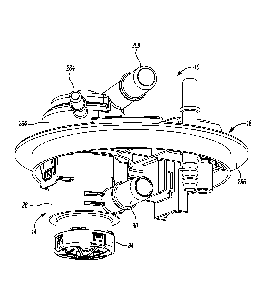
[0008] Figure 1 is a perspective view of an exemplary liquid vapor separator
drain valve (LVSDV) assembly in accordance with the principles of the present
disclosure;
[0009] Figure 2 is a perspective view of an exemplary liquid vapor separator
drain valve of the LVSDV assembly of Figure 1 in accordance with the
principles of
the present disclosure;
[0010] Figure 2A is an exploded or assembly view of the LVSDV of Figure 2
in accordance with the principles of the present disclosure;
[0011] Figure 3A is a side view of the LVSDV of Figure 2 in accordance with
the principles of the present disclosure;
[0012] Figure 3B is a sectional view of the LVSDV of Figure 3A in
accordance with the principles of the present disclosure;
[0013] Figure 4 is a bottom perspective view of a flange housing of the
LVSDV assembly of Figure 1 in accordance with the principles of the present
disclosure;
Page 3 of 16
CA 02929416 2016-05-02
WO 2015/069816
PCT/US2014/064203
[0014] Figure 5 is a top perspective view of the flange housing in
accordance with the principles of the present disclosure;
[0015] Figure 6 is a sectional view of the LVSDV assembly in accordance
with the principles of the present disclosure; and
[0016] Figure 7 is a schematic view of an exemplary evaporative system for
a vehicle including the LVSDV assembly in accordance with the principles of
the
present disclosure.
DESCRIPTION
[0017] With initial reference to Figure 1, an exemplary liquid vapor separator
drain valve (LVSDV) assembly is shown and generally identified at reference
numeral 10. In accordance with various aspects of the invention, the LVSDV
assembly 10 includes a LVSDV 14 and a flange member or housing 18 that is
removably sealingly coupled to a fuel tank (Figure 7). In this implementation,
the
flange member 18 is also configured to removably and sealingly receive the
LVSDV 14 in a snap-fit configuration. As will be discussed in greater detail
below,
the LVSDV assembly 10 provides for allowing fuel vapor to vent to a carbon
canister while protecting the carbon canister from liquid fuel. In one
exemplary
implementation, the LVSDV assembly 10 interfaces with a fuel delivery module
and various fuel tank vent valves while the LVSDV 14 is packaged in the fuel
tank.
[0018] In accordance with various aspects of the invention, the LVSDV
assembly 10 is advantageously configured in a more compact and less complex
manner thereby reducing cost and complexity of the vehicle fuel and
evaporative
systems while also reducing packaging space required within the fuel tank.
This
thereby provides for using a smaller fuel tank and/or positioning the LVSDV 14
in
the fuel tank while allowing fuel to rise higher than with conventional larger
and
more bulky vent valves. By providing a single device (i.e., the LVSDV assembly
10) with multiple functions, less connections with the fuel tank are required
and
those connections are confined within the fuel tank via the LVSDV assembly 10,
which reduces complexity and potential leak paths.
Page 4 of 16
CA 02929416 2016-05-02
WO 2015/069816
PCT/US2014/064203
[0019] For example and as will be discussed in greater detail below, the fuel
vapor vent valves are routed through the LVSDV assembly 10 such that the
LVSDV 14 can capture any liquid carry over (LCO) and thereby protect a carbon
canister from potential fuel contamination. The LVSDV assembly 10 is
configured
to coalesce LCO if present in the vapor venting lines of the evaporative
and/or fuel
systems. In addition, in one exemplary implementation, the LVSDV assembly 10
is configured to drain [CO with an integrated roll over drain valve, protect
for a
failed nozzle scenario, protect the evaporative system with a liquid trap
design,
and provide for venting with LCO in vapor venting lines and fuel in the liquid
separation chamber.
[0020] Continuing with reference to Figure 1 and with additional reference to
Figures 2-3B, the LVSDV 14 includes, in one exemplary implementation, an outer
body or housing 26 defining an external port 30 configured to be fluidly
coupled to
a fill limit vapor valve (FLVV) 34 of an exemplary evaporative system 38
schematically shown in Figure 7. The outer body 26 defines an upper internal
chamber 46 separated by a divider member 50 from a lower internal chamber 54.
The divider member 50 includes at least one passage 58 to provide selective
fluid
communication between the chambers 46, 54. The outer body 26 also defines an
open upper end 64, which forms an open upper end of chamber 46, and a lower
open end 68, which forms a lower open end of chamber 54. In the exemplary
implementation illustrated, the housing 26 includes a cylindrical shape such
that
the upper and lower internal chambers 46, 54 are cylindrical in shape with the
upper chamber 46 having a longer axial length than the lower chamber 54, as
can
be seen for example in Figures 3A-3B.
[0021] A lower valve 76 is movably positioned in the lower chamber 54 and,
in one exemplary implementation, is balanced by a biasing member 80. In one
exemplary implementation, the lower valve 76 is a float valve. A cap or
closure
member 84 is removably coupled to the lower end 68 of housing 26 so as to be
positioned under the float 76. The cap 84 is configured to support and/or
capture
the float 76 in lower chamber 54. In one exemplary implementation, the cap 84
is
perforated and is configured to be removably snap-fit to the outer body 26 via
tabs
Page 5 of 16
CA 02929416 2016-05-02
WO 2015/069816
PCT/US2014/064203
or cutouts 88 formed in an outer rim 92 of cap 84 and corresponding angled
projections 98 formed on outer body 26.
[0022] An upper end or side 102 of the float 76 includes a seal 106
configured to, when urged upward by liquid fuel, seal against the divider
member
50 so as to block or seal passage 58 and thereby seal lower internal chamber
54
from upper internal chamber 46. The seal 106, in the exemplary implementation
illustrated, includes a housing 110 movably coupled to the float 76 to provide
an
ability for the seal 106 to move relative to the float 76 in a situation
where, for
example, the liquid fuel urging the float 76 upward toward the divider member
50
provides an angled force on the float 76.
[0023] The LVSDV 14 includes an upper housing member 124 that is
removably coupled to the outer housing 26, as shown for example in Figures 2A-
3B. The upper housing member 124 includes a body 128 defining an upper end
134, a lower end 138 and a radially extending flange 142. The radially
extending
flange 142 defines two receptacles 146 configured to receive two tabs or
projections 152 axially extending from the upper end 64 of outer housing 26 to
removably couple the upper housing member 124 to the outer housing 26. When
the upper housing member 124 is removably coupled to the outer housing 26, a
portion 156 of the body 128 between the flange 142 and the lower end 138 is
positioned inside the upper chamber 46 such that the lower end 138 engages or
rests on the divider member 50. The body 128 includes a smaller diameter than
upper internal chamber 46 so as to be spaced apart therefrom when positioned
therein and form a chamber area 162 between the outer housing 26 and the body
128 of upper housing member 124. In one exemplary implementation, the upper
housing member 124 partitions the upper chamber 46 into an outer chamber 162
between the outer housing 26 and the upper housing body 128 and an internal
chamber area 172 inside the body 128.
[0024] The lower end 138 of upper housing member 124 includes one or
more cut-outs or recesses 168 so as to form a fluid communication path between
the outer chamber area 162 and the internal chamber area 172 inside
cylindrical
body 128 when upper housing member 124 is assembled to outer housing 26.
Page 6 of 16
CA 02929416 2016-05-02
WO 2015/069816
PCT/US2014/064203
The upper end 134 of housing member 124 defines a central opening or port 176
in communication with the internal chamber 172 defined by the body 128 of
housing member 124. The radial extending flange 142 defines one or more
peripheral apertures or passages 184 spaced radially outward from the port 176
and the body 128 and configured to be in fluid communication with outer
chamber
area or portion 162 when housing member 124 is assembled to outer body 26. A
radially outer portion of the radially extending flange 142 engages the upper
end
64 of housing 26 when the upper housing member 124 is assembled thereto.
[0025] An upper valve 194 is positioned inside upper housing member 124
in the internal chamber 172 and includes a body 198 defining an upper end 202
and a lower end 206 having cut-outs or recesses 210. In one exemplary
implementation, the upper valve 194 is an upper float valve that is configured
to
engage or rest on divider member 50 via the lower end 206 when positioned in
LVSDV 14. The upper end 202 includes a smaller width or diameter 214 than a
lower portion 218 and includes a seal 224 movably coupled thereto, such that
when the upper valve 194 is urged upward by liquid fuel, the seal 224 is
configured to seal against the upper end 134 of housing member 124 thereby
sealing or closing off port 176. The upper housing member 124 can also define
one or more peripheral passages 234 in the body 128 and above the flange 142
proximate the upper end 134. These passages 234 provide a fluid communication
path through body 128 and ultimately to passage 58 of divider 50 via a space
between the upper housing member 124 and upper float valve 194 regardless of a
position of the upper float valve 194.
[0026] As can be seen in Figures 2A and 3B, the LVSDV 14 includes two in-
line (i.e., common central axis), vertically stacked floats or float valves
76, 194
each having sealing capability associated with a respective upper end thereof.
In
other words, the upper and lower chambers are concentric and vertically or
serially
stacked and the upper and lower valves 76, 194 are concentric and vertically
or
serially stacked. In the exemplary implementation shown in the various
figures,
the upper float valve 194 includes a generally up-side-down U-shape
configuration
defining an internal chamber 244 having a diameter or width slightly smaller
than
Page 7 of 16
CA 02929416 2016-05-02
WO 2015/069816
PCT/US2014/064203
the corresponding diameter or width of surrounding internal chamber 172. In a
rest condition, float valve 194 is vertically spaced apart from the upper end
134 of
upper housing member 124 and thus port 176. Fluid, such as fuel, entering
chambers 162, 172 and 244 can urge upper float valve 194 upward into sealing
engagement with the upper end 134 of housing member 24 thereby sealing off
port 176 from the carbon canister.
[0027] With particular reference to Figures 4-7 and continuing reference to
Figures 1-3B, the flange member or housing 18 will now be discussed in greater
detail. As briefly mentioned above, the LVSDV 14 can be removably coupled to
the flange member 18, which is sealingly connected to a fuel tank 250 and in
fluid
communication with an internal volume 254 defined thereby, as shown in Figure
7.
The flange member 18 includes a body 260 defining a raised receptacle or
cavity
264 configured to receive the LVSDV 14. The receptacle 264 includes a first
internal wall 272 and a second, smaller diameter internal wall 276. In one
exemplary implementation, the second internal wall 276 is positioned above the
first internal wall 272, which may be in or below the receptacle 264.
[0028] A first flange port 284 extends from and/or is in communication with
an aperture or opening in the first wall 272 and a second flange port 288
extends
from an area defined by or above the second internal wall 276. A third port
292
extends from a bottom of flange member 18 and is in communication with the
first
port 284. The first and second flange ports 284, 288 each extend from the
receptacle 264 or adjacent body 260 while being fluidly coupled to different
chambers when the flange member 18 is coupled to the LVSDV 14. In the
exemplary implementation illustrated, the first and second flange ports 284,
288
extend in the same or substantially the same direction from body 260 and are
vertically and horizontally spaced apart from each other. For example, the
second
flange port 288 is positioned above the first flange port 284. Such a
configuration
can provide for, among other advantages, a more compact flange member 18 for
vehicle packaging purposes. The flange member body 260 also defines a
perimeter flange area 296 for removable sealingly coupling the flange member
18
to the fuel tank 250, as shown for example in Figure 7.
Page 8 of 16
CA 02929416 2016-05-02
WO 2015/069816
PCT/US2014/064203
[0029] The LVSDV 14, when assembled together, includes a first seal 304,
such as an o-ring, proximate an upper end of the outer body 26, and a second
seal 308, such as an o-ring, proximate the upper end 134 of the upper housing
member 124, as shown for example in Figure 3B. The first and second seals 304,
308 are positioned in a stacked concentric relationship such that the second
seal
308 is vertically and horizontally spaced apart from the first seal 304. With
this
sealing configuration, the LVSDV 14, when assembled to the flange member 18,
automatically seals against the flange member 18 and automatically separates
the
LVSDV chambers associated with the first and second ports 284, 288.
[0030] For example, the first seal 304 seals to or against the first internal
wall 272 and the second seal 308 seals to or against the second internal wall
276.
This places, among other things, the first port 284 in communication with the
outer
chamber area 162 between outer body 26 and upper housing member 124 via
peripheral passages 184; the second port 288 in communication with upper end
port 176; and the third port 292 in communication with the second port 288 and
upper end port 176. With this configuration, the upper valve 194 can seal off
the
upper port 176 and thus communication with the carbon canister via port 288
while
allowing the first port 284 to communicate with the outer chamber area 162. In
addition, the second port 288 can also communicate with the outer chamber area
162 and thus drain liquid fuel independent from the upper port 176 because the
second port 288 is lower than the first port 284 and associated with the outer
chamber 162. The LVSDV 14 is, in one exemplary implementation, removably
coupled to the flange member 18 by guiding the upper end 134 of upper housing
member 124 into the receptacle 264 such that tabs or projections 298 on an
exterior of outer body 26 are received in a recess or cutout of projections
300
extending from a lower side or surface 312 of flange member 18.
[0031] Operation of the LVSDV 14 will now be discussed in conjunction with
the flange member 18 and the exemplary evaporative system shown in Figure 7.
In one exemplary aspect, the third flange port 292 is fluidly coupled to a
remote
mounted grade vent valve 318, which is desirably positioned higher in the fuel
tank
250 relative to the LVSDV 14. The first flange port 284 is fluidly coupled to
the fuel
Page 9 of 16
CA 02929416 2016-05-02
WO 2015/069816
PCT/US2014/064203
fill tube recirculation line 324 and the second flange port 288 is fluidly
coupled to
the carbon canister 328. As mentioned above, the third flange port 292 is in
communication with the second flange port 288 outside of and/or independent of
the LVSDV 14. The LVSDV 14 external port 30 is in fluid communication with the
fill limit vapor valve (FLVV) 34, which is positioned in the fuel tank 250.
[0032] In the exemplary implementation illustrated, the external port 30 is
configured to provide a main vapor release path for the fuel tank system. In
operating conditions where the float valves 76, 194 are in a rest or non-
sealing
position (e.g., not urged into a sealing position by liquid fuel), fuel vapor
can flow
into outer chamber or portion 162 of upper chamber 46 via external port 30 and
flow through the flange peripheral passages 184, through radial wall passages
234
in upper housing member 124, through port 176, and out flange port 288 toward
the carbon canister 328. Fuel vapor can also flow into chamber 172 of upper
valve 124 via the perforated cap 84, lower internal chamber 54 and passage 58
in
divider member 50.
[0033] If liquid fuel flows down the recirculation tube 324 and enters the
LVSDV 14 via flange port 284, it can be diverted from a flow path toward the
carbon canister 328 by the LVSDV assembly 10. More particularly, in the
exemplary implementation illustrated, such liquid fuel flow from the
recirculation
tube 324 leaves flange port 284 and flows through peripheral flange passages
184
and into chamber portion 162, where the fuel can flow into the internal
chamber
244 via the cut-outs 168, 210 in the lower ends 138, 206 of the housing member
124 and float valve 194, respectively. The liquid fuel then drains through
passage
58 and the perforations in cap 84. If the volume of liquid fuel flowing into
chamber
244 in the manner discussed above is greater than the drain rate, then the
upper
float valve 194 will be urged upward and seal off port 176 to protect the
carbon
canister 328. With port 176 sealed off, the liquid fuel from the recirculation
tube
324 is not able to reach second flange port 288 and thus the carbon canister
328,
but can still drain to the fuel tank.
[0034] If the vehicle is on a grade and the FLVV 34 would potentially leak or
malfunction, the upper float valve 194 can act as a back-up to prevent liquid
fuel
Page 10 of 16
CA 02929416 2016-05-02
WO 2015/069816
PCT/US2014/064203
from reaching the carbon canister 328. To the extent such a scenario would
happen, fuel entering the FLVV 34 could potentially reach the LVSDV 14 via
external port 30. In this situation, the liquid fuel would enter chamber 244
via the
cut-outs and, to the extent the fuel enters at a rate greater than it drains,
seal 224
would be urged against upper end 134 via float 194 to seal off port 58. This
would
again, in a similar manner as discussed above, prevent such fuel from reaching
the carbon canister 328.
[0035] In a potential scenario where the LVSDV 14 and FLVV 34 are
submerged in liquid fuel, to the extent possible without a roll-over
condition, the
LVSDV 14 would seal off any potential for liquid fuel to enter the carbon
canister
328 via the LVSDV 14, while the remote grade vent valve 318 would provide for
venting of the fuel tank 250 vapor to the carbon canister 328. While the float
valves 76, 194 would seal off passages/ports 58 and 176 of the LVSDV 14, the
remote grade vent valve 318 is positioned and plumbed to the LVSDV 14 via
third
flange port 292 such that the fuel tank would still be able to vent fuel vapor
via the
third flange port 292 and second flange port 288. In this regard, and as can
be
seen in Figure 7, the remote grade vent valve 318 is positioned at or
substantially
at an opposite side of the fuel tank 250 as the LVSDV 14, and mounted higher
(toward a top of fuel tank 250).
[0036] It will be understood that the mixing and matching of features,
elements, methodologies and/or functions between various examples may be
expressly contemplated herein so that one skilled in the art would appreciate
from
the present teachings that features, elements and/or functions of one example
may be incorporated into another example as appropriate, unless described
otherwise above.
Page 11 of 16