Note: Descriptions are shown in the official language in which they were submitted.
SYSTEMS AND METHODS FOR PISTON ASSEMBLIES
CROSS-REFERENCE TO RELATED APPLICATIONS
This application claims priority to U.S. Provisional Patent Application No.
61/907,009, filed on November 21, 2013.
BACKGROUND
The present application relates to systems and methods for piston assemblies,
including such assemblies that can be used in a lift mechanism for assisting
with opening
and closing of a large pivoting body, for example and without limitation a
hood for a class 8
truck.
An exemplary lift mechanism can include a lockable gas spring arrangement, for
example as shown and described in U.S. Patent Application Publication No.
2013/0187315.
In operation, the piston assembly of the lift mechanism can provide a damped
force to a
large pivoting body, for example and without limitation a hood for a class 8
truck, over a
range of motion of the large pivoting body between an open position and a
closed position.
When a lift mechanism is attached to a large pivoting body, such as a hood of
a truck, during
operation of the truck, the hood can be subjected to vibration that can be
transferred to the
lift mechanism. In this manner, the piston assembly of the lift mechanism can
provide a
damping force in response to the vibration, which can result in increased wear
to the hood
and lift mechanism.
As such, there is an opportunity for an improved piston assembly that can be
used in a
lift mechanism for assisting with opening and closing of a large pivoting
body, while
reducing or preventing wear on the lift mechanism due to vibrational forces.
1
Date Recue/Date Received 2021-05-12
CA 02929505 2016-05-02
WO 2015/077628 PCT/US2014/066924
SUMMARY
Systems and methods for piston assemblies are disclosed herein.
In accordance with the disclosed subject matter, a piston assembly is
provided.
The piston assembly includes a piston housing defining an interior and having
a first
housing end and a second housing end, a piston rod having a first rod end
extending
into the interior and moveable therein between an extended position toward the
first
housing end and a retracted position toward the second housing end, a first
plate
joined to the piston rod proximate the first rod end, a second plate joined to
the piston
rod and spaced apart a distance along the piston rod from the first plate, and
a piston
head slidably joined to the piston rod between the first plate and the second
plate.
In some embodiments, the piston assembly can include a first energy storage
member disposed within the housing proximate the first housing end, and can
include
a second energy storage member disposed proximate the second housing end. At
least
one of the first and second energy storage members can include a spring. When
the
piston rod is in the extended position, the first plate can engage the first
energy
storage member, and when the piston rod is in the retracted position, the
second plate
can engage the second energy storage member. When the piston rod is urged from
the
extended position toward the retracted position, the piston head can slide
along the
piston rod from the first plate toward the second plate.
In some embodiments, the piston assembly can include a sleeve surrounding at
least a portion of the piston rod and having a first sleeve end and a second
sleeve end.
The first plate can be fixed to the sleeve proximate the first sleeve end. The
second
plate can be fixed to the sleeve proximate the second sleeve end. The piston
head can
be slidable along the sleeve between the first and second plates. The sleeve
can have
2
CA 02929505 2016-05-02
WO 2015/077628
PCT/US2014/066924
an outer diameter greater than the first rod end and less than a remainder of
the piston
rod.
In some embodiments, the piston assembly can include a fastener disposed
proximate the first rod end to limit or inhibit movement of at least the first
plate
.. toward the first rod end. The first rod end can have a reduced diameter
relative a
remainder of the piston rod.
In some embodiments, each of the first and second plates can include a
washer. Each of the first and second plates can include a notched washer.
Alternatively, at least one of the first plate and second plate can include a
disc washer.
Additionally or alternatively, the at least one of the first plate and second
plate can
include an aperture defined therethrough. The aperture can have a cross
dimension
selected to provide a selected amount of damping to the piston rod when the
piston
head is in an intermediate position between the first plate and the second
plate. When
the piston head is urged from the intermediate position to the retracted
position, a first
amount of damping can be provided to the piston rod, and the first amount of
damping
can be greater than the selected amount of damping. The first place can
include a disc
washer and the second plate can include a notched washer. Alternatively, the
second
place can include a disc washer and the first place can include a notched
washer. As a
further alternative, the first place and the second plate can each include a
disc washer.
In accordance with other aspects of the disclosed subject matter, a lift
assembly configured to provide a damping force to a pivotable body during
pivoting
of the pivotable body relative a stationary body between a closed position and
an open
position is provided. The lift assembly can have a first lift end and a second
lift end.
The lift assembly includes a piston assembly. The piston assembly can include
any
.. and all of the features described herein. The lift assembly includes a
first fitting
3
CA 02929505 2016-05-02
WO 2015/077628
PCT/US2014/066924
operably coupled to the piston assembly proximate the first lift end and
configured to
engage the pivotable body. The lift assembly includes a second fitting
operably
coupled to the piston assembly proximate the second lift end and configured to
engage the stationary body.
In some embodiments, when the first fitting is engaged to the pivotable body
and the second fitting is engaged to the stationary body, and when the
pivotable body
is urged from the closed position toward the open position to an intermediate
position,
the lift assembly can provide no damping force to the pivotable body. When the
pivotable body is further urged from the intermediate position toward the open
position, the lift assembly can provide a damping force to the pivotable body.
When
the pivotable body is urged from the open position to the intermediate
position, the lift
assembly can provide a damping force to the pivotable body. When the pivotable
body is urged from the intermediate position toward the closed position, the
lift
assembly can provide no damping force to the pivotable body.
Certain variations of the subject matter disclosed herein are set forth in the
accompanying drawings and further description below. Other features and
advantages of the subject matter described herein will be apparent from the
description and drawings, and from the claims.
BRIEF DESCRIPTION OF THE DRAWINGS
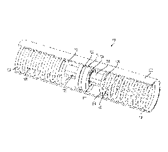
FIG. 1 is a perspective view of an exemplary embodiment of a piston
assembly in accordance with the disclosed subject matter, with portions of the
housing cut away for purpose of illustration.
FIG. 2 is an exploded perspective view of the piston assembly of FIG. 1, with
portions of the housing cut away for purpose of illustration.
4
CA 02929505 2016-05-02
WO 2015/077628
PCT/US2014/066924
FIG. 3 is a cross-sectional view of the piston assembly of FIG. 1 in an open
position.
FIG. 4 is a cross-sectional view of the piston assembly of FIG. 1 in a closed
position.
FIG. 5 is a cross-sectional view of the piston assembly of FIG. 1 in a
centered
position.
FIG. 6 is a perspective view of an alternative embodiment of a piston
assembly in accordance with the disclosed subject matter, with portions of the
housing cut away for purpose of illustration.
FIG. 7 is a cross-sectional view of the piston assembly of FIG. 6.
FIG. 8 is a side view of a lift mechanism partially in cross-section, joined
to a
pivotable body and a stationary body, and including a piston assembly
according to
the disclosed subject matter.
FIG. 9 is a diagram illustrating additional details of exemplary piston
assemblies according to the disclosed subject matter,
DETAILED DESCRIPTION
According to aspects of the disclosed subject matter, systems and techniques
for piston assemblies generally include a piston housing, a piston rod
disposed at least
partially within the piston housing, a first plate joined to the piston rod, a
second plate
joined to the piston rod and spaced apart from the first plate, and a piston
head joined
to the piston rod and slidable between the first plate and the second plate.
Piston assemblies according to the disclosed subject matter can be used in a
lift mechanism for assisting with opening and closing of a large pivoting body
joined
to a stationary body. For purpose of illustration only and not limitation, the
stationary
body can be a vehicle, such as a class 8 truck, and the large pivoting body
can be a
5
hood for the class 8 truck. An exemplary lift mechanism can include a lockable
gas spring
arrangement, for example as shown and described in U.S. Patent Application
Publication No.
2013/0187315.
With reference to FIGS. 1 and 2, an exemplary piston assembly 100 according to
the
disclosed subject matter is illustrated. The piston assembly 100 includes a
piston housing 102
defining an interior and having a first housing end and a second housing end.
The piston
housing 102 can be configured as a closed housing, and as such, can be filled
with a fluid
medium, including but not limited to, air, compressed gas, oil or any other
suitable medium.
Piston housing 102 can be any suitable shape. For example, and as embodied
herein, piston
housing 102 can be cylindrical.
Additionally, and as embodied herein, piston assembly 100 includes a piston
rod 108
extending at least partially into the interior of piston housing 102. As
embodied herein, piston
rod 108 can have a first rod end 128 extending into the interior of piston
housing 102. Piston
rod 108 can have any suitable size and shape. For example, and as embodied
herein, first rod
end 128 can have a diameter less than a diameter of a remainder of piston rod
108. For
purpose of illustration, and not limitation, first rod end 128 can have a
diameter within a
range of 4 nun to 16 mm, and as embodied herein can have a diameter of 8 mm,
and the
remainder of piston rod 108 can have a diameter within a range of 6 mm to 20
mm, and as
embodied herein can have a diameter of 14 mm. Alternatively, piston rod 108
can have a
constant diameter along its length.
Furthermore, and as embodied herein, piston rod 108 can include one or more
engagements to secure one or more components of piston assembly 100 to piston
rod 108.
For example, and as embodied herein, piston rod 108 can include an
6
Date Recue/Date Received 2021-05-12
CA 02929505 2016-05-02
WO 2015/077628
PCT/US2014/066924
engagement region 110 proximate first rod end 128, Engagement region 110 can
be
any suitable engagement, and for purpose of illustration and not limitation,
engagement region can be a threated engagement.
In addition, and as embodied herein, piston assembly 100 includes a first
plate
114 joined to the piston rod 108 proximate the first rod end 128. Piston
assembly 100
further includes a second plate 112 joined to the piston rod 108 and spaced
apart a
distance along the piston rod 108 from the first plate 114. For purpose of
illustration,
and not limitation, first plate 114 can be spaced apart a distance within a
range of 5
mm to 100 mm from second plate 112, and as embodied herein can be spaced apart
a
distance of 10 mm from second plate 112. First and second plates 112. 114 can
have
any suitable configuration. For example, and as embodied herein, first plate
114 and
second plate 112 each can be configured as washers. With reference to FIGS. 1
and
2, as embodied herein, first plate 114 can be configured as a disc washer.
Additionally, and as embodied herein, second plate 112 can be configured as a
notched washer. Alternatively, first plate 114 can be configured as a notched
washer,
and second plate 112 can be configured as a disc washer. As a further
alternative,
first and second plates 112, 114 each can be configured as a disc washer.
With continued reference to FIGS. I and 2, as embodied herein, piston
assembly 100 includes a piston head 116 slidably joined to piston rod 108
between
first plate 114 and second plate 112. In this manner, the distance between
first plate
114 and second plate 112 defines a floating region within which piston head
116 can
slide along piston rod 108, as discussed further herein. The length of free
travel of
piston head 116 can be selected and changed to increase or reduce the amount
of
undamped movement of the piston assembly 100 by increasing or decreasing the
distance between the first plate 114 and second plate 112. For purpose of
illustration
7
CA 02929505 2016-05-02
WO 2015/077628
PCT/US2014/066924
and not limitation, the length of free travel of piston head 116 between first
plate 114
and second plate 112 can be selected within a range of 5 mm to 100 mm, and as
embodied herein, can be 10 mm. As embodied herein, piston head 116 can include
a
shoulder 117 protruding outwardly from one or both opposing surfaces thereof.
For
.. purpose of illustration, and not limitation, shoulder 117 can prevent
locking of piston
head 116 with first plate 114 or second plate 112, for example due to
hydraulic
locking.
Additionally, and as embodied herein, piston assembly 100 can include a
sleeve 118 disposed at least partially about at least a portion of first rod
end 128 of
piston rod 108. Sleeve 118 can have an inner diameter sized to engage piston
rod 108
in a frictional engagement. For purpose of illustration and not limitation, as
embodied
herein, sleeve 118 can have an inner diameter of 8 mm and an outer diameter of
10
mm. First and second plates 112, 114 can he joined to sleeve 118 by any
suitable
engagement. For example, first and second plates 112, 114 can have an inner
diameter sized to engage outer diameter of sleeve 118 in a frictional
engagement. For
purpose of illustration and not limitation, as embodied herein, first and
second plates
112, 114 can have an inner diameter of 10 mm. Alternatively, first and second
plates
112, 114 can be joined to sleeve 118 by threaded engagement or any other
suitable
engagement. Piston head 116 can have an inner diameter sized to be disposed
about
and slide along sleeve 118. For purpose of illustration and not limitation,
piston head
116 can have an inner diameter within a range of 4 mm to 16 mm, which can be
selected to allow piston head 116 to slide along sleeve 118, if provided,
and/or first
rod end 128. Sleeve 118 can be formed of any suitable material, such as, for
purpose
of illustration and not limitation metals, such as steel or aluminum, or
polymeric
materials, such as plastic. Alternatively, first and second plates 112, 114
and piston
8
CA 02929505 2016-05-02
WO 2015/077628
PCT/US2014/066924
head 116 can be joined directly to piston rod 108 without sleeve 118 disposed
thereon. Additionally or alternatively, piston assembly 100 can include a
fastener 120
secured to engagement region 110 of first rod end 128. For example, and not
limitation, fastener 120 can be configured as a nut, such as a hexagonal nut.
Furthermore, and as embodied herein, first and second plates 112, 114 and
piston head 116 each can have any suitable size to move within piston housing
102.
For purpose of illustration and as embodied herein, one or more of first and
second
plates 112, 114 and piston head 116 can have an outer diameter similar to the
inner
diameter of piston housing 102. As such, first and second plates 112, 114
and/or
.. piston head 116 can form a fluid-tight seal with piston housing 102. For
example, and
as embodied herein, first and second plates 112, 114 and piston head 116 each
can
have an outer diameter corresponding to inner diameter of piston housing 102.
In this
manner, damping forces can be provided by movement of first and second plates
112,
114 and/or piston head 116, as discussed further herein. For purpose of
illustration
and not limitation, first and second plates 112, 114 and piston head 116 each
can have
an outer diameter of 13 mm to 38 mm, which can be chosen to form a fluid-tight
seal
between any or all of these components and piston housing 102, Piston head 116
can
further include a gasket 122 disposed therein. Gasket 122 can improve the
fluid-tight
seal formed between piston head 116 and piston housing 102. Gasket 122 can be
formed from any suitable material to provide a fluid-tight seal, including but
not
limited to rubber, urethane, fluoroelastomer, nylon, polytetrafluoroethylene,
or any
other suitable material. First plate 112 and/or second plate 114 can also
include a
gasket to improve a fluid-tight seal formed between first plate 112 and/or
second plate
114 and piston housing 102.
9
CA 02929505 2016-05-02
WO 2015/077628
PCT/US2014/066924
In addition, and as embodied herein, first plate 114 and/or second plate 112
can include an aperture defined therethrough. For example, and as embodied
herein,
first plate 114 can include aperture 126 defined therethrough. The size of
aperture
126 can be selected to adjust an amount of damping provided by the movement of
first plate 114 through the fluid medium in piston housing 102. For example,
increasing the size of aperture 126 can reduce an amount of damping from
movement
of first plate 114, via movement of piston rod 108, as discussed further
herein.
Conversely, decreasing the size of aperture 126 can increase an amount of
damping
from movement of first plate 114. For purpose of illustration and not
limitation,
aperture 126 can have a diameter within a range of 0.1 mm and 3 mm.
Additionally,
first plate 112 can include a plurality of apertures 126 to further adjust the
amount of
damping. Additionally or alternatively, second plate 112 can include an
aperture
therethrough, which can have a diameter selected to further adjust damping
from
movement of second plate 112.
Referring still to FIGS. I and 2, piston assembly 100 can include one or more
energy storage features to provide energy to first plate 114, second plate
112, and/or
piston head 116. For purpose of illustration and not limitation, and as
embodied
herein, piston assembly 100 can include a first energy storage member 106
disposed
between an end wall of piston housing 102 and first plate 114. Additionally,
and as
embodied herein, piston assembly 100 can include a second energy storage
member
104 disposed between an opposing end wall of piston housing 102 and second
plate
112. First and second energy storage members 104, 106 can be any suitable
energy
storage member. For example, and as embodied herein, first and second energy
storage members 104, 106 each can be configured as a mechanical spring.
Alternatively, one or both of first energy storage member 104 and second
energy
CA 02929505 2016-05-02
WO 2015/077628
PCT/US2014/066924
storage member 106 can be configured as a compressed gas, electromechanical
energy storage, electromagnetic energy storage or any other suitable energy
storage to
provide a force to the first plate 104, second plate 106 or piston head 116.
Referring now to FIGS. 3-5, exemplary operation of piston assembly 100 is
illustrated. With reference to FIG. 3, piston assembly 100 is shown with
piston rod
108 in a retracted position. For purpose of illustration and not limitation,
the retracted
position of piston rod 108 can correspond to an open position of a pivotable
body
joined to piston assembly 100, In the retracted position, second plate 112
engages
second energy storage member 104, which can provide tension force, for example
to
slow the speed of the pivotable body moving from the closed position toward
the open
position and support the pivotable body in the open position.
With reference to FIG. 4, piston assembly 100 is shown with piston rod 108 in
an extended position. When the pivotable body is urged toward the closed
position,
piston head 116 engages second plate 112 and damps the motion of piston rod
108. In
the extended position, first plate 114 engages first energy storage member
106, which
can provide a lifting force to urge the pivotable body toward the open
position, for
example to assist a user in opening the pivotable body. First energy storage
member
106 can also slow the speed of the pivotable body moving from the open
position to
the closed position.
With reference to FIG. 5, piston assembly 100 is shown with piston rod 108 in
an intermediate position between the extended position and retracted position.
When
the pivotable body is in the closed position, piston rod 108 can oscillate
between the
extended position and the intermediate position, which can occur for example
and
without limitation, and as embodied herein due to vibrational forces applied
to the
piston assembly 100. In the intermediate position, piston head 116 can float
between
11
CA 02929505 2016-05-02
WO 2015/077628
PCT/US2014/066924
first plate 114 and second plate 112. That is, piston head 116 can slide
within the
floating region defined between first plate 114 and second plate 112 without
engaging
either first plate 114 and second plate 112. In this manner, piston head 116
can be
prevented or inhibited from applying damping force to the piston rod 108 and
pivotable body. When the pivotable body is urged further toward the open
position,
for example by lifting the pivotable body by a user, second plate 112 engages
piston
head 116, which applies a damping force to piston rod 108, as illustrated for
example
in FIG. 3.
As discussed herein, first plate 114 and second plate 112 can be selected and
adjusted
.. to allow piston assembly 100 to provide a desired amount of damping when
piston
head 116 is in the intermediate position, for example and without limitation,
and as
embodied herein due to vibrational forces, without affecting an amount of
damping
provided by piston assembly 100 when piston head 116 is moving to the
retracted
position or the extended position, for example and without limitation, and as
embodied herein due to opening or closing of a pivotable body. That is, as
discussed
herein, first plate 114 and/or second plate 112 can be configured as a disc
washer
having an aperture 126 sized to select an amount of damping provided by piston
assembly 100 while piston head 116 is in the intermediate position. For
example, and
as embodied herein, first plate 114 can be configured as a disc washer having
an
aperture 126, and second plate 112 can be configured as a notched washer. In
this
manner, piston assembly 100 can provide a selectable amount of damping in the
intermediate position, and as embodied herein, the selectable amount of
damping can
be less than the amount of damping provided by piston assembly 100 when piston
head 116 moves to the retracted position or the extended position by movement
of the
piston rod 108.
12
CA 02929505 2016-05-02
WO 2015/077628 PCT/US2014/066924
Alternatively, first and second plates 112, 114 can each be configured as a
disc
washer having an aperture 126 sized to select an amount of damping provided by
piston assembly 100 while piston head 116 is in the intermediate position. In
this
manner, piston assembly 100 can be configured to provide a selectable amount
of
damping in the intermediate position, and as embodied herein, the selectable
amount
of damping in this configuration can be greater than the amount of damping
provided
when only one of first and second plates 112, 114 is configured as a disc
washer, yet
still provide less damping than when piston head 116 moves to the retracted
position
or the extended position by movement of the piston rod 108.
As a further alternative, with reference to FIGS. 6 and 7, an alternative
embodiment of a piston assembly 100' can include a first plate 114' and second
plate
112 each configured as a notched washer. In this configuration, piston
assembly 100'
can provide little or no damping while piston head 116 is in the intermediate
position,
and can provide desired damping when piston head 116 moves to the retracted
position or the extended position by movement of the piston rod 108. Piston
assembly 100' can include any or all of the features described herein with
respect to
piston assembly 100.
FIG. 9 is a diagram illustrating a damping force compared to velocity of
exemplary piston heads moving within the intermediate position. As shown in
FIG. 9,
piston assemblies were tested by oscillating a piston head 116 with a 10 mm
within
the intermediate position. A first configuration included a piston assembly
having
first and second plates each configured as notched washers, A second
configuration
included a piston assembly having a first plate configured as a disc washer
having a
2.5 mm aperture (also referred to as an orifice) and a second plate configured
as a
notched washer. A third configuration included a piston assembly having a
first plate
13
CA 02929505 2016-05-02
WO 2015/077628
PCT/US2014/066924
configured as a disc washer having a 1.0 mm aperture or orifice and a second
plate
configured as a notched washer. A fourth configuration included a piston
assembly
having a first plate and a second plate each configured as a disc washer
having no
aperture or orifice. A fifth configuration included a piston assembly having a
first
plate and a second plate each configured as a disc washer having no aperture
or
orifice, and moving within a fluid medium having a greater weight (e.g., an
SAE
viscosity grade of 50) than the first through fourth configurations (e.g.,
having an
SAE viscosity grade of 10).
According to another aspect of the disclosed subject matter, a lift assembly
is
provided. With reference to FIG. 8, an exemplary lift assembly 200 can include
a
piston assembly according to the disclosed subject matter. For purpose of
illustration
and not limitation, and as embodied herein, lift assembly 200 can include
piston
assembly 100, which can include any or all of the features of piston assembly
100
and/or piston assembly 100' described herein.
Lift assembly 200 can provide a damping force to a pivotable body during
pivoting of the pivotable body relative a stationary body between a closed
position
and an open position is provided. Lift assembly 200 can include a first
fitting 202
joined to piston assembly 100 proximate a first lift end. As embodied herein,
first
fitting 202 can be configured to engage a pivotable body 300. Lift assembly
200 can
include a second fitting 204 joined to piston assembly 100 proximate a second
lift
end. As embodied herein, second fitting 204 can be configured to engage a
stationary
body 400. First fitting 202 and second fitting 204 can be any suitable
fitting, such as,
without limitation, a socket for engagement with a ball to form a ball and
socket joint.
Lift assembly 210 can include a locking element 214. Further details of an
exemplary
14
locking element 214 are described in U.S. Patent Application Publication No.
2013/0187315.
Referring again to FIGS. 3-5, when first fitting 202 is engaged to pivotable
body 300
and second fitting 204 is engaged to stationary body 400, and when pivotable
body 300 is
urged from the closed position toward the open position to an intermediate
position, lift
assembly 200 can provide no damping force to pivotable body 300, for example
via piston
assembly 100 and piston rod 108 as illustrated in FIG. 5. When pivotable body
300 is further
urged from the intermediate position toward the open position, lift assembly
200 can provide
a damping force to pivotable body 300, for example via piston assembly 100 and
piston rod
108 as illustrated in FIG. 3. When pivotable body 300 is urged from the open
position to the
intermediate position, lift assembly 200 can provide a damping force to
pivotable body 300,
for example via piston assembly 100 and piston rod 108 as illustrated in FIG.
4. When
pivotable body 300 is urged from the intermediate position toward the closed
position, lift
assembly 200 can provide no damping force to pivotable body 300, for example
via piston
assembly 100 and piston rod 108 as illustrated in FIG. 5.
The piston assemblies and lift assemblies described herein can be formed from
any
suitable materials. For example and without limitation, components of the
piston assembly
and lift assembly can be formed from metals, such as steel and aluminum,
polymeric
materials, rubber, or any other suitable materials.
As described herein, a piston assembly can be configured to reduce or
eliminate
damping forces when a pivoting body, such as a hood, is in a closed position
and subject to
vibration, such as during vehicle operation, while allowing the lift mechanism
to provide
damping force when the lid is moved between the open and closed positions to
assist with
opening and closing of the hood.
Date Recue/Date Received 2021-05-12
CA 02929505 2016-05-02
WO 2015/077628
PCT/US2014/066924
For example and as described herein, the floating piston can thus allow for
little or no damping during vibration, thereby reducing damaging forces to the
hood
and attachment components. In this manner, full damping can be provided during
full
compression and full extension travel of the lift mechanism to allow for
normal
.. operation of the truck hood. As such, damping can reduced or eliminated
entirely
using the piston assembly and techniques according to the disclosed subject
matter.
The foregoing merely illustrates the principles of the disclosed subject
matter.
Various modifications and alterations to the described embodiments will be
apparent
to those skilled in the art in view of the teachings herein. It will thus be
appreciated
that those skilled in the art will be able to devise numerous techniques
which,
although not explicitly described herein, embody the principles of the
disclosed
subject matter and are thus within its spirit and scope.
16