Note: Descriptions are shown in the official language in which they were submitted.
PROCESSES FOR PRODUCING EFFECTS LAYERS
FIELD OF THE INVENTION
[001] The present invention relates to the field of processes for producing
optical effect layers
(OEL) comprising magnetically oriented platelet-shaped magnetic or
magnetisable pigment
particles. In particular, the present invention provides processes for
producing said OELs as anti-
counterfeit means on security documents or security articles or for decorative
purposes.
BACKGROUND OF THE INVENTION
[002] It is known in the art to use inks, compositions, coatings or layers
containing oriented
magnetic or magnetisable pigment particles, particularly also optically
variable magnetic or
magnetisable pigment particles, for the production of security elements, e.g.
in the field of security
documents. Coatings or layers comprising oriented magnetic or magnetisable
pigment particles
are disclosed for example in US 2,570,856; US 3,676,273; US 3,791,864; US
5,630,877 and US
5,364,689. Coatings or layers comprising oriented magnetic color-shifting
pigment particles,
resulting in particularly appealing optical effects, useful for the protection
of security documents,
have been disclosed in WO 2002/090002 A2 and WO 2005/002866 Al.
[003] Security features, e.g. for security documents, can generally be
classified into "covert"
security features on the one hand, and "overt" security features on the other
hand. The protection
provided by covert security features relies on the concept that such features
are difficult to detect,
typically requiring specialized equipment and knowledge for detection, whereas
"overt" security
features rely on the concept of being easily detectable with the unaided human
senses, e.g. such
features may be visible and/or detectable via the tactile senses while still
being difficult to produce
and/or to copy. However, the effectiveness of overt security features depends
to a great extent
on their easy recognition as a security feature.
[004] Magnetic or magnetisable pigment particles in printing inks or coatings
allow for the
production of magnetically induced images, designs and/or patterns through the
application of a
corresponding magnetic field, causing a local orientation of the magnetic or
magnetisable pigment
particles in the unhardened coating, followed by hardening the latter. The
result is a fixed
magnetically induced image, design or pattern. Materials and technologies for
the orientation of
magnetic or magnetisable pigment particles in coating compositions have been
disclosed in US
2,418,479; US 2,570,856; US 3,791,864, DE 2006848-A, US 3,676,273, US
5,364,689, US
6,103,361, EP 0 406 667 Bl; US 2002/0160194; US 2004/70062297; US
2004/0009308; EP 0
710 508 Al; WO 2002/09002 A2; WO 2003/000801 A2; WO 2005/002866 Al; WO
2006/061301
1
Date Recue/Date Received 2021-04-22
Al. In such a way, magnetically induced patterns which are highly resistant to
counterfeit can be
produced. The security element in question can only be produced by having
access to both, the
magnetic or magnetisable pigment particles or the corresponding ink, and the
particular
technology employed to print said ink and to orient said pigment in the
printed ink.
[005] Examples of dynamic security features based on magnetically induced
images, designs
or patterns providing the optical illusion of movement have been developed
including without
limitation rolling-bar effects and moving rings effects.
[006] For example, US 7,047,883 discloses the creation of a dynamic optically
variable effect
known as the "rolling bar" feature. The "rolling bar" feature provides the
optical illusion of
movement to images comprising oriented magnetic or magnetisable pigments. US
7,517,578 and
WO 2012/104098 Al respectively disclose "double rolling bar" and "triple
rolling bar" features,
said features seeming to move against each other upon tilting. A printed
"rolling bar" type image
shows one or more contrasting bands which appear to move ("roll") as the image
is tilted with
respect to the viewing angle. Such images are known to be easily recognized by
the man on the
street and the illusive aspect cannot be reproduced by commonly available
office equipment for
color scanning, printing and copying.
[007] For example, US 8,343,615, EP 0 232 567 07 A2, WO 2011/092502 and US
2013/0084411 disclose moving-ring images displaying an apparently moving ring
with changing
viewing angle ("rolling ring" or "moving ring" effect).
[008] The literature, such as for example in "Special Effect Pigments", G.
Pfaff, 2nd Revised
Edition, 2008, pages 43 and 116-117, teaches that large reflective particles
are preferred for
producing images, designs or patterns because they have a large flat surface,
exhibit a uniform
reflection of incident light thus leading to excellent lustre and brilliance,
whereas small particles
exhibit an increased light scattering and refraction thus causing reduced
light reflection and
inferior brilliance. Furthermore, it is known in the art that the qualities
expressed by saturation,
brightness, opacity of inks or compositions are affected by the size of the so-
comprised pigment
particles. For example, large optical effect pigment particles exhibit a
higher chroma than
corresponding smaller pigment particles. Therefore, the man skilled in the art
typically uses
reflective pigment particles having a large size, in particular optically
variable pigment particles or
optically variable magnetic or magnetisable pigment particles for producing
optical effect layers.
For example, the prior art discloses particles with an individual particle
size lying in a range
between 2 and 200 um (microns). WO 2002/073250 Al discloses optically variable
magnetic or
magnetisable pigment particles having a size between 20 and 30 um. WO
2011/012520 A2
discloses flake-shaped particles having a diameter of typically between 10 to
50 um. WO
2
Date Recue/Date Received 2021-04-22
2006/061301 Al discloses that a large particle size (flake diameter in the
range of 10 to 50 m)
and a size distribution which is as homogeneous as possible, are desirable, in
order to yield the
optimum effect. US 8,025,952 discloses that the typical size of magnetic
particles for inks is in the
range of from 10 m to 100 m.
[009] As taught by the prior art, optically reflective non-spherical pigment
particles having a large
size, in particular optically variable non-spherical pigment particles having
a large size, have been
widely preferred for producing optical effect layers. While there are only
limited indications
available in the art describing preferred particle sizes for reflective non-
spherical magnetic or
magnetisable pigment particles or optically variable non-spherical magnetic or
magnetisable
pigment particles, those indications also point towards large particle sizes
to obtain magnetically
oriented optical effect layers with high reflectivity, chroma and/or
colorshifting properties when
applied as a coating. Optically reflective non-spherical pigment particles
having a large size, in
particular optically variable non-spherical pigment particles having a large
size, have a tendency
to align without any external force parallel to the optical effect layer
surface as a consequence of
their large size, thereby producing higher reflective optical effect layers.
The reflectivity of optical
effect layers produced with optically reflective non-spherical pigment
particles having a small size
is negatively impacted as a consequence of the increased light scattering
resulting from the
increased numbers of pigment particles edges and the fact that the pigments
are more randomly
oriented than in layers produced with coating compositions comprising larger
particles.
[010] Therefore, a need remains for processes to produce optical effect layers
(OELs) based on
magnetically oriented platelet-shaped pigment particles, said OELs being
sophisticated and/or
displaying an eye-catching dynamic effect and exhibiting a high contrast
and/or improved
reflectivity in comparison with the prior art.
SUMMARY OF THE INVENTION
[011] Accordingly, it is an object of the present invention to overcome the
deficiencies of the
prior art as discussed above. This is achieved by the provision of a process
for producing an
optical effect layer (OEL) on a substrate, said process comprising the steps
of:
a) applying on a substrate surface a coating composition comprising i)
platelet-shaped magnetic
or magnetisable pigment particles and ii) a binder material, said coating
composition being in a
first state,
3
Date Recue/Date Received 2021-04-22
b) exposing the coating composition to a dynamic magnetic field of a first
magnetic-field-
generating device so as to bi-axially orient at least a part of the platelet-
shaped magnetic or
magnetisable pigment particles,
c) exposing the coating composition of step b) to a static magnetic field of a
second magnetic-
field-generating device, thereby mono-axially re-orienting at least a part of
the platelet-shaped
magnetic or magnetisable pigment particles, and
d) hardening the coating composition of step c) to a second state so as to fix
the platelet-shaped
magnetic or magnetisable pigment particles in their adopted positions and
orientations.
[012] Also described herein are OELs produced by the process described herein
and security
documents as well as decorative elements or objects comprising one or more
optical OELs
described herein.
[013] Also described herein methods of manufacturing a security document or a
decorative
element or object, comprising:
- providing a security document or a decorative element or object, and
- providing an optical effect layer such as those described herein, in
particular such as those
obtained by the process described herein, so that it is comprised by the
security document or
decorative element or object.
[014] The present invention enables the use of platelet-shaped magnetic or
magnetisable
pigment particles, irrespective of their particle size, to produce optical
effect layers exhibiting high
chroma, brightness, high contrast and high resolution. Furthermore, very small
platelet-shaped
magnetic or magnetisable pigment particles that are traditionally considered
as an inferior grade
compared to large magnetic or magnetisable pigment particles known in the art
to produce high
quality and high resolution magnetically induced images may be used to provide
high quality
OELs. By allowing the use of platelet-shaped magnetic or magnetisable pigment
particles,
irrespective of their particle size, the process described herein
advantageously provides the
freedom to use more classical or conventional printing elements, such as
screen printing,
flexography, rotogravure and intaglio printing. Moreover, the OELs produced by
the process
described herein and using small pigment particles may also have a reduced
thickness and
therefore an increased flexibility in comparison with the prior art thus
exhibit an improvement in
application or printing versatility while maintaining or improving optical
properties, resolution and
reflectivity. Moreover, several optical effect layers may also be more easily
superimposed without
excessively increasing the total thickness of the stack.
4
Date Recue/Date Received 2021-04-22
BRIEF DESCRIPTION OF DRAWINGS
[015] The optical effect layer (OEL) described herein and its production are
now described in
more detail with reference to the drawings and to particular embodiments,
wherein
Fig. 1 schematically illustrates a platelet-shaped pigment particle.
Fig. 2 schematically illustrates a first example of a first magnetic-
field-generating device
for bi-axially orienting magnetic or magnetisable platelet-shaped pigment
particles.
Fig. 3A-E photographic images of an OEL, said OEL comprising oriented
platelet-shaped
magnetic or magnetisable pigment particles and being produced by a process
according to the present invention.
Fig. 4 schematically illustrates an example of a first magnetic-field-
generating device for
bi-axially orienting platelet-shaped magnetic or magnetisable pigment
particles.
Fig. 5 photographic images of an OEL, said OEL comprising oriented
platelet-shaped
magnetic or magnetisable pigment particles and being produced by a process
according to the present invention.
DETAILED DESCRIPTION
Definitions
[016] The following definitions are to be used to interpret the meaning of the
terms discussed in
the description and recited in the claims.
[017] As used herein, the indefinite article "a" indicates one as well as more
than one and does
not necessarily limit its referent noun to the singular.
[018] As used herein, the term "about" means that the amount, value or limit
in question may be
the specific value designated or some other value in its neighbourhood.
Generally, the term
"about" denoting a certain value is intended to denote a range within 5% of
the value. As one
example, the phrase "about 100" denotes a range of 100 5, i.e. the range
from 95 to 105.
Generally, when the term "about" is used, it can be expected that similar
results or effects
according to the invention can be obtained within a range of 5% of the
indicated value. However,
a specific amount, value or limit supplemented with the term "about" is
intended herein to disclose
as well the very amount, value or limit as such, i.e. without the "about"
supplement.
Date Recue/Date Received 2021-04-22
[019] As used herein, the term "and/or" means that either all or only one of
the elements of said
group may be present. For example, "A and/or B" shall mean "only A, or only B,
or both A and B".
In the case of "only A", the term also covers the possibility that B is
absent, i.e. "only A, but not
B".
[020] The term "substantially parallel" refers to deviating less than 200 from
parallel alignment.
Preferably, the term "substantially parallel" refers to not deviating more
than 10 from parallel
alignment.
[021] The term "at least partially" is intended to denote that the following
property is fulfilled to a
certain extent or completely. Preferably, the term denotes that the following
property is fulfilled to
at least 50% or more.
[022] The terms "substantially" and "essentially" are used to denote that the
following feature,
property or parameter is either completely (entirely) realized or satisfied or
to a major degree that
does adversely affect the intended result. Thus, the term "substantially" or
"essentially" preferably
means at least 80%.
[023] The term "comprising" as used herein is intended to be non-exclusive and
open-ended.
Thus, for instance a coating composition comprising a compound A may include
other compounds
besides A. However, the term "comprising" also covers, as a particular
embodiment thereof, the
more restrictive meanings of "consisting essentially of" and "consisting of',
so that for instance "a
coating composition comprising a compound A" may also (essentially) consist of
the compound
A.
[024] The term "coating composition" refers to any composition which is
capable of forming an
optical effect layer on a solid substrate and which can be applied
preferentially but not exclusively
by a printing method. The coating composition comprises at least the platelet-
shaped magnetic
or magnetisable pigment particles described herein and a binder.
[025] The term "optical effect layer (OEL)" as used herein denotes a layer
that comprises
magnetically oriented platelet-shaped magnetic or magnetisable pigment
particles and a binder,
wherein the orientation of the platelet-shaped magnetic or magnetisable
pigment particles is fixed
within the binder so as to form a magnetically induced image.
[026] As used herein, the term "optical effect coated substrate (OEC)" is used
to denote the
product resulting from the provision of the OEL on a substrate. The OEC may
consist of the
substrate and the OEL, but may also comprise other materials and/or layers
other than the OEL.
[027] The term "security element" or "security feature" is used to denote an
image or graphic
element that can be used for authentication purposes. The security element or
security feature
can be an overt and/or a covert security element.
6
Date Recue/Date Received 2021-04-22
[028] The term "partially simultaneously" as used herein denotes that two
steps are partly
performed simultaneously, i.e. the times of performing each of the steps
partially overlap.
[029] In one aspect, the present invention relates to processes for producing
optical effect layers
(OEL) as well as optical effect layers (OEL) obtained therefrom and optical
effect coatings (OEC);
i.e. substrates comprising one or more OEL obtained therefrom. The process
according to the
present invention comprises the steps of:
a) applying on a substrate surface the coating composition described herein,
said coating
composition being in a first state,
b) exposing the coating composition to the dynamic magnetic field of a
magnetic-field-generating
device so as to bi-axially orient at least a part of the platelet-shaped
magnetic or magnetisable
pigment particles,
c) exposing the coating composition of step b) to the static magnetic field of
a second magnetic-
field-generating device, thereby mono-axially re-orienting at least a part of
platelet-shaped
magnetic or magnetisable pigment particles, and
d) hardening the coating composition of step c) to a second state so as to fix
the platelet-shaped
magnetic or magnetisable pigment particles in their adopted positions and
orientations.
[030] In contrast to needle-shaped pigment particles which can be considered
as one-
dimensional particles, platelet-shaped pigment particles are two-dimensional
particles due to the
large aspect ratio of their dimensions as can be seen in Figure 1. As shown in
Figure 1, a platelet-
shaped pigment particle can be considered as a two-dimensional structure
wherein the
dimensions X and Y are substantially larger than dimension Z. Platelet-shaped
pigment particles
are also referred in the art as oblate particles or flakes. Such pigment
particles may be described
with a main axis X corresponding to the longest dimension crossing the pigment
particle and a
second axis Y perpendicular to X which also lies within said pigment
particles.
[031] Since the coating composition described herein is to be provided on a
substrate surface,
it is necessary that the coating composition comprising at least the binder
material and the
platelet-shaped magnetic or magnetisable pigment particles is in a form that
allows processing of
the coating composition. The applying step a) described herein is preferably
carried out by a
printing process preferably selected from the group consisting of screen
printing, rotogravure
printing, flexography printing and intaglio printing (also referred in the art
as engraved copper
plate printing and engraved steel die printing), more preferably selected from
the group consisting
of screen printing, rotogravure printing and flexography printing. These
processes are well-known
to the skilled man and are described for example in Printing Technology, J. M.
Adams and P. A.
7
Date Recue/Date Received 2021-04-22
Dolin, Delmar Thomson Learning, 5th Edition. Further, subsequently to,
partially simultaneously
or simultaneously with the application of the coating composition described
herein on the
substrate surface described herein, the platelet-shaped magnetic or
magnetisable pigment
particles are oriented by applying a succession of magnetic fields so as to
align the platelet-
shaped magnetic or magnetisable pigment particles along the field lines.
Subsequently to or
partially simultaneously with the steps of orienting/aligning the platelet-
shaped magnetic or
magnetisable pigment particles by applying magnetic fields, the orientation of
the platelet-shaped
magnetic or magnetisable pigment particles is fixed or frozen. The coating
composition must thus
noteworthy have a first state, i.e. a liquid or pasty state, wherein the
coating composition is wet
or soft enough, so that the platelet-shaped magnetic or magnetisable pigment
particles dispersed
in the coating composition are freely movable, rotatable and/or orientable
upon exposure to a
magnetic field, and a second hardened (e.g. solid) state, wherein the platelet-
shaped magnetic
or magnetisable pigment particles are fixed or frozen in their respective
positions and orientations.
[032] Such a first and second state is preferably provided by using a certain
type of coating
composition. For example, the components of the coating composition other than
the platelet-
shaped magnetic or magnetisable pigment particles may take the form of an ink
or coating
composition such as those which are used in security applications, e.g. for
banknote printing. The
aforementioned first and second states can be provided by using a material
that shows an
increase in viscosity in reaction to a stimulus such as for example a
temperature change or an
exposure to an electromagnetic radiation. That is, when the fluid binder
material is hardened or
solidified, said binder material converts into the second state, i.e. a
hardened or solid state, where
the platelet-shaped magnetic or magnetisable pigment particles are fixed in
their current positions
and orientations and can no longer move nor rotate within the binder material.
[033] As known to those skilled in the art, ingredients comprised in an ink or
coating composition
to be applied onto a surface such as a substrate and the physical properties
of said ink or coating
composition must fulfil the requirements of the process used to transfer the
ink or coating
composition to the substrate surface. Consequently, the binder material
comprised in the ink or
coating composition described herein is typically chosen among those known in
the art and
depends on the coating or printing process used to apply the ink or coating
composition and the
chosen hardening process.
[034] The OEL described herein comprises platelet-shaped magnetic or
magnetisable pigment
particles that, due to their shape, have non-isotropic reflectivity. The
platelet-shaped magnetic or
magnetisable pigment particles are dispersed in the binder material being at
least partially
transparent to electromagnetic radiation of one or more wavelength ranges in
the range of 200
8
Date Recue/Date Received 2021-04-22
nm to 2500 nm and have a specific orientation for providing a desired optical
effect.
[035] The orientation of the platelet-shaped magnetic or magnetisable pigment
particles in the
binder material to obtain the OEL described herein is achieved by two
orientation steps, said steps
being carried out by i) bi-axially orienting the platelet-shaped magnetic or
magnetisable pigment
particles in accordance with an external dynamic magnetic field of a first
magnetic¨field-
generating device, and subsequently ii) mono-axially re-orienting the platelet-
shaped magnetic or
magnetisable pigment particles in accordance with a static external magnetic
field of a second
magnetic¨field-generating device.
[036] Carrying out a bi-axial orientation means that the platelet-shaped
magnetic or
magnetisable pigment particles are made to orientate in such a way that their
two main axes are
constrained. That is, each platelet-shaped magnetic or magnetisable pigment
particle can be
considered to have a major axis in the plane of the pigment particle and an
orthogonal minor axis
in the plane of the pigment particle. The major and minor axes of the platelet-
shaped magnetic or
magnetisable pigment particles are each caused to orient according to the
dynamic magnetic
field. Effectively, this results in neighbouring platelet-shaped magnetic
pigment particles that are
close to each other in space to be essentially parallel to each other. In
order to perform a bi-axial
orientation, the platelet-shaped magnetic pigment particles must be subjected
to a strongly time-
dependent external magnetic field.
[037] Put another way, bi-axial orientation aligns the planes of the platelet-
shaped magnetic or
magnetisable pigment particles so that the planes of said pigment particles
are oriented to be
essentially parallel relative to the planes of neighbouring (in all
directions) platelet-shaped
magnetic or magnetisable pigment particles. In an embodiment, both the major
axis and the minor
axis perpendicular to the major axis described hereabove of the planes of the
platelet-shaped
magnetic or magnetisable pigment particles are oriented by the dynamic
magnetic field so that
neighbouring (in all directions) pigment particles have their major and minor
axes aligned with
each other.
[038] Carrying out a mono-axial orientation step means that the platelet-
shaped magnetic
pigment particles are made to orientate in such a way that only the
orientation of their main axis
is constrained. Effectively, this results in neighbouring platelet-shaped
magnetic pigment particles
having their main (longest) axis parallel to each other, while their minor
axis in the plane of the
platelet-shaped magnetic or magnetisable pigment particles is not constrained.
Consequently,
planes of neighbouring platelet-shaped magnetic pigment particles are not
necessarily parallel
after a mono-axial orientation step. In order to perform mono-axial
orientation, the particles are
subjected to an essentially static magnetic field.
9
Date Recue/Date Received 2021-04-22
[039] According to one embodiment, the step of carrying out a bi-axial
orientation of the platelet-
shaped magnetic or magnetisable pigment particles leads to a magnetic
orientation wherein the
platelet-shaped magnetic or magnetisable pigment particles have their two main
axes
substantially parallel to the substrate surface. For such an alignment, the
platelet-shaped
magnetic or magnetisable pigment particles are planarised within the coating
composition on the
substrate and are oriented with both their X-axis and Y-axis shown in Figure 1
parallel with the
substrate surface.
[040] According to another embodiment, the step of carrying a bi-axial
orientation of the platelet-
shaped magnetic or magnetisable pigment particles leads to a magnetic
orientation wherein the
platelet-shaped magnetic or magnetisable pigment particles have a first axis
within the X-Y plane
substantially parallel to the substrate surface and a second axis being
perpendicular to said first
axis at a substantially non-zero elevation angle to the substrate surface.
[041] According to another embodiment, the step of carrying a bi-axial
orientation of the platelet-
shaped magnetic or magnetisable pigment particles leads to a magnetic
orientation wherein the
platelet-shaped magnetic or magnetisable pigment particles have their X-Y
plane parallel to an
imaginary spheroid surface.
[042] According to another aspect of the present disclosure, there is provided
a process for
producing an optical effect layer (OEL) on a substrate, said process
comprising the steps of:
a) applying on a substrate surface a coating composition comprising i)
platelet-shaped magnetic
or magnetisable pigment particles and ii) a binder material, said coating
composition being in a
first state,
b) exposing the coating composition to a dynamic magnetic field of a first
magnetic-field-
generating device to dynamically change an orientation of at least a part of
the platelet-shaped
magnetic or magnetisable pigment particles according to the dynamic magnetic
field in a region
of the coating composition, preferably so as to cause planes of neighbouring
(in all directions)
platelet-shaped magnetic or magnetisable pigment particles of said at least
part of the pigment
particles to be essentially parallel to each other in the (macroscopic) region
of the coating
composition,
c) exposing the coating composition of step b) to a static magnetic field of a
second magnetic-
field-generating device, thereby aggregately re-orienting at least some of the
platelet-shaped
magnetic or magnetisable pigment particles in the region, and
d) hardening the coating composition of step c) to a second state so as to fix
the platelet-shaped
magnetic or magnetisable pigment particles in their adopted positions and
orientations.
Date Recue/Date Received 2021-04-22
[043] The coating compositions described herein comprise platelet-shaped
magnetic or
magnetisable pigment particles comprising a magnetic material and having a
particle size (d50)
from about 1 lam to about 200 p.m. Herein the term "size" denotes a
statistical property of the
ensemble of platelet-shaped magnetic or magnetisable pigment particles. As
known in the art,
pigment particles, flake pigments and other comminuted materials can be
characterized by
measuring a particle size distribution (PSD) of a sample. Such PSDs typically
describe the
fractional amount (relative to total number, weight or volume) of particles in
the sample as a
function of a size-related characteristic of individual particles. A commonly
used size-related
characteristic describing individual particles is the "circle equivalent" (CE)
diameter, which
corresponds to the diameter of a circle that would have the same area as an
orthographic
projection of the particle. It is common in the art to express a PSD as the
relative volume of
particles as a function of the CE diameter, and for platelet-shaped particles,
the volume is
calculated as proportional to the CE diameter to the power of 2. This
definition of a PSD will be
used throughout the present application. For convenience, statistics of PSDs
are calculated from
the results using the CE diameter rather than reporting the entire PSD. In
this application,
standard percentile readings are reported:
D(v,50) (hereafter abbreviated as d50) is the value of the CE diameter, in
microns, which
separates the PSD in two parts of equal cumulated volume: the lower part
represent 50% of the
cumulated volume of all particles, corresponding to those particles with a CE
diameter smaller
than d50; the upper part represents 50% of the cumulated volume of particles,
corresponding to
those particles with a CE diameter larger than d50. D50 is also known as the
median of the volume
distribution of particles.
[044] A variety of experimental methods are available to measure PSD's
including without
limitation sieve analysis, electrical conductivity measurements (using a
Coulter counter), laser
diffraction and direct optical granulomtery. Direct optical granulometry was
used to determine
PSDs cited in this application (instrument: Malvern Morphologi G3; sample
preparation: 0.2 wt-%
pigment particle dispersion in a solvent-based varnish, screen-printed using a
90T mesh on glass
microscope slides).
[045] As mentioned hereabove, the process described herein enables the use of
platelet-
shaped magnetic or magnetisable pigment particles, irrespective of their
particle size within the
range from about 1 p.m to about 200 p.m described herein, to produce OELs
exhibiting high
chroma, brightness, high contrast and high resolution. By allowing the use of
platelet-shaped
magnetic or magnetisable pigment particles, irrespective of their particle
size, the process
described herein advantageously provides the versatility in the printing
process of the coating
11
Date Recue/Date Received 2021-04-22
composition. The size of platelet-shaped magnetic or magnetisable pigment
particles described
herein should be selectively chosen so as to generate OELs exhibiting optimum
optical properties
for screen printing, rotogravure printing, flexography printing, intaglio
printing or equivalent
methods used in the art. Typically platelet-shaped magnetic or magnetisable
pigment particles
having a particle size (d50) from about 1 um to about 200 um are particularly
suitable for coating
techniques. Typically platelet-shaped magnetic or magnetisable pigment
particles having a
particle size (d50) from about 1 um to about 50 um are particularly suitable
for screen printing.
Typically platelet-shaped magnetic or magnetisable pigment particles having a
particle size (d50)
from about 1 um to about 25 um are particularly suitable for rotogravure
printing and flexography
printing. Typically platelet-shaped magnetic or magnetisable pigment particles
having a particle
size (d50) from about 1 um to about 30 um are particularly suitable for
intaglio printing. Moreover,
the OELs produced by the process described herein while using small pigment
particles may also
advantageously have a reduced thickness and therefore a increased flexibility
in comparison with
the prior art thus exhibit an improvement of printing performance while
maintaining or improving
optical properties, resolution and reflectivity.
[046] In the OEL described herein, the platelet-shaped magnetic or
magnetisable pigment
particles are provided in such a manner as to form a visually dynamic element,
in particular a
dynamic security element. Herein, the term "dynamic appearance" denotes that
the appearance
and the light reflection of the element changes depending on the viewing
angle. Put differently,
the appearance of the security element is different when viewed from different
angles, i.e. the
security element exhibits a different appearance e.g. when viewed from a
viewing angle of about
90 as compared to a viewing angle of about 22.5 , both with respect to the
plane of the OEL.
This behaviour is caused by the orientation of the platelet-shaped magnetic or
magnetisable
pigment particles having non-isotropic reflectivity and/or by the properties
of the platelet-shaped
magnetic or magnetisable pigment particles as such, having a viewing angle
dependent
appearance (such as platelet-shaped optically variable magnetic or
magnetisable pigment
particles described later).
[047] Due to their platelet shape, the reflectivity of the platelet-shaped
magnetic of magnetisable
pigment particles is non-isotropic as the visible area of the particle depends
on the direction from
which it is viewed. In one embodiment, the platelet-shaped magnetic or
magnetisable pigment
particles having non-isotropic reflectivity due to their non-spherical shape
may further have an
intrinsic non-isotropic reflectivity, such as for instance in platelet-shaped
optically variable
magnetic or magnetisable pigment particles, due to their structure comprising
layers of different
reflectivity and refractive indexes. In this embodiment, the platelet-shaped
magnetic or
12
Date Recue/Date Received 2021-04-22
magnetisable pigment particles comprise platelet-shaped magnetic or
magnetisable pigment
particles having intrinsic non-isotropic reflectivity, such as platelet-shaped
optically variable
magnetic or magnetisable pigment particles.
[048] Suitable examples of platelet-shaped magnetic or magnetisable pigment
particles
described herein include without limitation pigment particles comprising a
magnetic metal
selected from the group consisting of cobalt (Co), iron (Fe), gadolinium (Gd)
and nickel (Ni); a
magnetic alloy of iron, manganese, cobalt, nickel or a mixture of two or more
thereof; a magnetic
oxide of chromium, manganese, cobalt, iron, nickel or a mixture of two or more
thereof; or a
mixture of two or more thereof. The term "magnetic" in reference to the
metals, alloys and oxides
is directed to ferromagnetic or ferrimagnetic metals, alloys and oxides.
Magnetic oxides of
chromium, manganese, cobalt, iron, nickel or a mixture of two or more thereof
may be pure or
mixed oxides. Examples of magnetic oxides include without limitation iron
oxides such as
hematite (Fe203), magnetite (Fe304), chromium dioxide (Cr02), magnetic
ferrites (MFe204),
magnetic spinels (MR204), magnetic hexaferrites (MFe12019), magnetic
orthoferrites (RFe03),
magnetic garnets M3R2(A04)3, wherein M stands for two-valent metal, R stands
for three-valent
metal, and A stands for four-valent metal.
[049] Examples of platelet-shaped magnetic or magnetisable pigment particles
described herein
include without limitation pigment particles comprising a magnetic layer M
made from one or more
of a magnetic metal such as cobalt (Co), iron (Fe), gadolinium (Gd) or nickel
(Ni); and a magnetic
alloy of iron, cobalt or nickel, wherein said platelet-shaped magnetic or
magnetisable pigment
particles may be multilayered structures comprising one or more additional
layers. Preferably, the
one or more additional layers are layers A independently made from one or more
materials
selected from the group consisting of metal fluorides such as magnesium
fluoride (MgF2), silicium
oxide (Si0), silicium dioxide (5i02), titanium oxide (TiO2), zinc sulphide
(ZnS) and aluminium oxide
(A1203), more preferably silicium dioxide (SiO2); or layers B independently
made from one or more
materials selected from the group consisting of metals and metal alloys,
preferably selected from
the group consisting of reflective metals and reflective metal alloys, and
more preferably selected
from the group consisting of aluminium (Al), chromium (Cr), and nickel (Ni),
and still more
preferably aluminium (Al); or a combination of one or more layers A such as
those described
hereabove and one or more layers B such as those described hereabove. Typical
examples of
the platelet-shaped magnetic or magnetisable pigment particles being
multilayered structures
described hereabove include without limitation NM multilayer structures, A/M/A
multilayer
structures, A/M/B multilayer structures, A/B/M/A multilayer structures,
A/B/M/B multilayer
structures, A/B/M/B/A multilayer structures, B/M multilayer structures, B/M/B
multilayer structures,
13
Date Recue/Date Received 2021-04-22
B/A/M/A multi layer structures, B/A/M/B multi layer structures,
B/A/M/B/A/multilayer structures,
wherein the layers A, the magnetic layers M and the layers B are chosen from
those described
hereabove.
[050] Due to their magnetic characteristics, the platelet-shaped magnetic or
magnetisable
pigment particles described herein are machine readable, and therefore coating
compositions
comprising those pigment particles may be detected for example with specific
magnetic detectors.
Coating compositions comprising the platelet-shaped magnetic or magnetisable
pigment particles
described herein may therefore be used as a covert or semi-covert security
element
(authentication tool) for security documents.
[051] Optically variable elements, such as for example pigment particles,
inks, coatings or layers
are known in the field of security printing. Optically variable elements (also
referred in the art as
colorshifting or goniochromatic elements) exhibit a viewing-angle or incidence-
angle dependent
color, and are used to protect banknotes and other security documents against
counterfeiting
and/or illegal reproduction by commonly available color scanning, printing and
copying office
equipment.
[052] The platelet-shaped magnetic or magnetisable pigment particles may
comprise platelet-
shaped optically variable magnetic or magnetisable pigment particles and/or
platelet-shaped
magnetic or magnetisable pigment particles having no optically variable
properties. Preferably, at
least a part of the platelet-shaped magnetic or magnetisable pigment particles
described herein
is constituted by platelet-shaped optically variable magnetic or magnetisable
pigment particles.
[053] In addition to the overt security provided by the colorshifting property
of optically variable
magnetic or magnetisable pigment particles, which allows easily detecting,
recognizing and/or
discriminating an article or security document carrying an ink, coating
composition, coating or
layer comprising the platelet-shaped optically variable magnetic or
magnetisable pigment
particles described herein from their possible counterfeits using the unaided
human senses, the
optical properties of the platelet-shaped optically variable magnetic or
magnetisable pigment
particles may also be used as a machine readable tool for the recognition of
the OEL. Thus, the
optical properties of the platelet-shaped optically variable magnetic or
magnetisable pigment
particles may simultaneously be used as a covert or semi-covert security
feature in an
authentication process wherein the optical (e.g. spectral) properties of the
pigment particles are
analyzed. The use of platelet-shaped optically variable magnetic or
magnetisable pigment
particles in coating compositions for producing an OEL enhances the
significance of the OEL as
a security feature in security document applications, because such materials
(i.e. platelet-shaped
optically variable magnetic or magnetisable pigment particles) are reserved to
the security
14
Date Recue/Date Received 2021-04-22
document printing industry and are not commercially available to the public.
[054] As mentioned above, preferably at least a part of the platelet-shaped
magnetic or
magnetisable pigment particles is constituted by platelet-shaped optically
variable magnetic or
magnetisable pigment particles. These can more preferably be selected from the
group consisting
of platelet-shaped magnetic thin-film interference pigment particles, platelet-
shaped magnetic
cholesteric liquid crystal pigment particles, platelet-shaped interference
coated pigment particles
comprising a magnetic material and mixtures of two or more thereof.
[055] Platelet-shaped magnetic thin film interference pigment particles are
known to those
skilled in the art and are disclosed e.g. in US 4,838,648; WO 2002/073250 A2;
EP 0 686 675 Bl;
WO 2003/000801 A2; US 6,838,166; WO 2007/131833 Al; EP 2 402 401 Al and in the
documents cited therein. Preferably, the platelet-shaped magnetic thin film
interference pigment
particles comprise pigment particles having a five-layer Fabry-Perot
multilayer structure and/or
pigment particles having a six-layer Fabry-Perot multilayer structure and/or
pigment particles
having a seven-layer Fabry-Perot multilayer structure.
[056] Preferred five-layer Fabry-Perot multilayer structures consist of
absorber/dielectric/reflector/dielectric/absorber multilayer structures
wherein the reflector and/or
the absorber is also a magnetic layer, preferably the reflector and/or the
absorber is a magnetic
layer comprising nickel, iron and/or cobalt, and/or a magnetic alloy
comprising nickel, iron and/or
cobalt and/or a magnetic oxide comprising nickel (Ni), iron (Fe) and/or cobalt
(Co).
[057] Preferred six-layer Fabry-Perot multilayer structures consist of
absorber/dielectric/reflector/magnetic/dielectric/absorber multilayer
structures.
[058] Preferred seven-layer Fabry Perot multilayer structures consist of
absorber/dielectric/reflector/magnetic/reflector/dielectric/absorber
multilayer structures such as
disclosed in US 4,838,648.
[059] Preferably, the reflector layers described herein are independently made
from one or more
materials selected from the group consisting of metals and metal alloys,
preferably selected from
the group consisting of reflective metals and reflective metal alloys, more
preferably selected from
the group consisting of aluminium (Al), silver (Ag), copper (Cu), gold (Au),
platinum (Pt), tin (Sn),
titanium (Ti), palladium (Pd), rhodium (Rh), niobium (Nb), chromium (Cr),
nickel (Ni), and alloys
thereof, even more preferably selected from the group consisting of aluminium
(Al), chromium
(Cr), nickel (Ni) and alloys thereof, and still more preferably aluminium
(Al). Preferably, the
dielectric layers are independently made from one or more materials selected
from the group
consisting of metal fluorides such as magnesium fluoride (MgF2), aluminium
fluoride (AIF3),
cerium fluoride (CeF3), lanthanum fluoride (LaF3), sodium aluminium fluorides
(e.g. Na3AIF6),
Date Recue/Date Received 2021-04-22
neodymium fluoride (NdF3), samarium fluoride (SmF3), barium fluoride (BaF2),
calcium fluoride
(CaF2), lithium fluoride (LiF), and metal oxides such as silicium oxide (Si0),
silicium dioxide (SiO2),
titanium oxide (TiO2), aluminium oxide (A1203), more preferably selected from
the group consisting
of magnesium fluoride (MgF2) and silicium dioxide (SiO2) and still more
preferably magnesium
fluoride (MgF2). Preferably, the absorber layers are independently made from
one or more
materials selected from the group consisting of aluminium (Al), silver (Ag),
copper (Cu), palladium
(Pd), platinum (Pt), titanium (Ti), vanadium (V), iron (Fe) tin (Sn), tungsten
(W), molybdenum (Mo),
rhodium (Rh), Niobium (Nb), chromium (Cr), nickel (Ni), metal oxides thereof,
metal sulfides
thereof, metal carbides thereof, and metal alloys thereof, more preferably
selected from the group
consisting of chromium (Cr), nickel (Ni), metal oxides thereof, and metal
alloys thereof, and still
more preferably selected from the group consisting of chromium (Cr), nickel
(Ni), and metal alloys
thereof. Preferably, the magnetic layer comprises nickel (Ni), iron (Fe)
and/or cobalt (Co); and/or
a magnetic alloy comprising nickel (Ni), iron (Fe) and/or cobalt (Co); and/or
a magnetic oxide
comprising nickel (Ni), iron (Fe) and/or cobalt (Co). When magnetic thin film
interference pigment
particles comprising a seven-layer Fabry-Perot structure are preferred, it is
particularly preferred
that the magnetic thin film interference pigment particles comprise a seven-
layer Fabry-Perot
absorber/dielectric/reflector/magnetic/reflector/dielectric/absorber
multilayer structure consisting
of a Cr/MgF2/Al/M/Al/MgF2/Cr multilayer structure, wherein M a magnetic layer
comprising nickel
(Ni), iron (Fe) and/or cobalt (Co); and/or a magnetic alloy comprising nickel
(Ni), iron (Fe) and/or
cobalt (Co); and/or a magnetic oxide comprising nickel (Ni), iron (Fe) and/or
cobalt (Co).
[060] The magnetic thin film interference pigment particles described herein
may be multilayer
pigment particles being considered as safe for human health and the
environment and being
based for example on five-layer Fabry-Perot multilayer structures, six-layer
Fabry-Perot multilayer
structures and seven-layer Fabry-Perot multilayer structures, wherein said
pigment particles
include one or more magnetic layers comprising a magnetic alloy having a
substantially nickel-
free composition including about 40 wt-% to about 90 wt-% iron, about 10 wt-%
to about 50 wt-%
chromium and about 0 wt-% to about 30 wt-% aluminium. Typical examples of
multilayer pigment
particles being considered as safe for human health and the environment can be
found in EP 2
402 401 Al.
[061] Platelet-shaped magnetic thin film interference pigment particles
described herein are
typically manufactured by a conventional deposition technique for the
different required layers
onto a web. After deposition of the desired number of layers, e.g. by physical
vapour deposition
(PVD), chemical vapour deposition (CVD) or electrolytic deposition, the stack
of layers is removed
from the web, either by dissolving a release layer in a suitable solvent, or
by stripping the material
16
Date Recue/Date Received 2021-04-22
from the web. The so-obtained material is then broken down to platelet-shaped
pigment particles
which have to be further processed by grinding, milling (such as for example
jet milling processes)
or any suitable method so as to obtain pigment particles of the required size.
The resulting product
consists of flat platelet-shaped pigment particles with broken edges,
irregular shapes and different
aspect ratios. Further information on the preparation of suitable platelet-
shaped magnetic thin film
interference pigment particles can be found e.g. in EP 1 710 756 Al and EP 1
666 546 Al.
[062] Suitable platelet-shaped magnetic cholesteric liquid crystal pigment
particles exhibiting
optically variable characteristics include without limitation magnetic
monolayered cholesteric
liquid crystal pigment particles and magnetic multilayered cholesteric liquid
crystal pigment
particles. Such pigment particles are disclosed for example in WO 2006/063926
Al, US 6,582,781
and US 6,531,221. WO 2006/063926 Al discloses monolayers and pigment particles
obtained
therefrom with high brilliance and colorshifting properties with additional
particular properties such
as magnetisability. The disclosed monolayers and pigment particles, which are
obtained
therefrom by comminuting said monolayers, include a three-dimensionally
crosslinked cholesteric
liquid crystal mixture and magnetic nanoparticles. US 6,582,781 and US
6,410,130 disclose
platelet-shaped cholesteric multilayer pigment particles which comprise the
sequence Al/B/A2,
wherein A1 and A2 may be identical or different and each comprises at least
one cholesteric layer,
and B is an interlayer absorbing all or some of the light transmitted by the
layers A1 and A2 and
imparting magnetic properties to said interlayer. US 6,531,221 discloses
platelet-shaped
cholesteric multilayer pigment particles which comprise the sequence A/B and
optionally C,
wherein A and C are absorbing layers comprising pigment particles imparting
magnetic
properties, and B is a cholesteric layer.
[063] Suitable platelet-shaped interference coated pigments comprising one or
more magnetic
materials include without limitation structures consisting of a substrate
selected from the group
consisting of a core coated with one or more layers, wherein at least one of
the core or the one
or more layers have magnetic properties. For example, suitable platelet-shaped
interference
coated pigments comprise a core made of a magnetic material such as those
described
hereabove, said core being coated with one or more layers made of one or more
metal oxides, or
they have a structure consisting of a core made of synthetic or natural micas,
layered silicates
(e.g. talc, kaolin and sericite), glasses (e.g. borosilicates), silicium
dioxides (SiO2), aluminium
oxides (A1203), titanium oxides (TiO2), graphites and mixtures of two or more
thereof. Furthermore,
one or more additional layers such as colouring layers may be present.
[064] The platelet-shaped magnetic or magnetisable pigment particles described
herein may be
surface treated so at to protect them against any deterioration that may occur
in the coating
17
Date Recue/Date Received 2021-04-22
composition and/or to facilitate their incorporation in the coating
composition; typically corrosion
inhibitor materials and/or wetting agents may be used.
[065] Preferably, the coating composition described herein comprises the
platelet-shaped
magnetic or magnetisable pigment particles described herein dispersed in a
binder material.
Preferably, the platelet-shaped magnetic or magnetisable pigment particles are
present in an
amount from about 2 wt-% to about 40 wt-%, more preferably about 4 wt-% to
about 30 wt-%, the
weight percents being based on the total weight of the coating composition
comprising the binder
material, the platelet-shaped magnetic or magnetisable pigment particles and
other optional
components of the coating composition.
[066] In addition to the platelet-shaped magnetic or magnetisable pigment
particles (which may
or may not comprise or consist of platelet-shaped optically variable magnetic
or magnetisable
pigment particles), also non-magnetic or non-magnetisable pigment particles
may be comprised
in the coating compositions described herein. These particles may be color
organic or inorganic
pigment particles known in the art, having or not having optically variable
properties. Further, the
particles may be spherical or platelet-shaped and may have isotropic or non-
isotropic optical
reflectivity.
[067] The substrate described herein is preferably selected from the group
consisting of papers
or other fibrous materials, such as cellulose, paper-containing materials,
glasses, metals,
ceramics, plastics and polymers, metallised plastics or polymers, composite
materials and
mixtures or combinations of two or more thereof. Typical paper, paper-like or
other fibrous
materials are made from a variety of fibres including without limitation
abaca, cotton, linen, wood
pulp, and blends thereof. As is well known to those skilled in the art, cotton
and cotton/linen blends
are preferred for banknotes, while wood pulp is commonly used in non-banknote
security
documents. Typical examples of plastics and polymers include polyolefins such
as polyethylene
(PE) and polypropylene (PP), polyamides, polyesters such as poly(ethylene
terephthalate) (PET),
poly(1,4-butylene terephthalate) (PBT), poly(ethylene 2,6-naphthoate) (PEN)
and
polyvinylchlorides (PVC). Spunbond olefin fibres such as those sold under the
trademark Tyvek
may also be used as substrate. Typical examples of metalized plastics or
polymers include the
plastic or polymer materials described hereabove having a metal disposed
continuously or
discontinuously on their surface. Typical example of metals include without
limitation aluminium
(Al), chromium (Cr), copper (Cu), gold (Au), silver (Ag), alloys thereof and
combinations of two or
more of the aforementioned metals. The metallization of the plastic or polymer
materials
described hereabove may be done by an electrodeposition process, a high-vacuum
coating
process or by a sputtering process. Typical examples of composite materials
include without
18
Date Recue/Date Received 2021-04-22
limitation multilayer structures or laminates of paper and at least one
plastic or polymer material
such as those described hereabove as well as plastic and/or polymer fibres
incorporated in a
paper-like or fibrous material such as those described hereabove. Of course,
the substrate can
comprise further additives that are known to the skilled person, such as
fillers, sizing agents,
whiteners, processing aids, reinforcing or wet strengthening agents, etc. When
the OELs
produced according to the present invention are used for decorative or
cosmetic purposes
including for example fingernail lacquers, said OEL may be produced on other
type of substrates
including nails, artificial nails or other parts of an animal or human being.
[068] Should the OEL produced according to the present invention be on a
security document,
and with the aim of further increasing the security level and the resistance
against counterfeiting
and illegal reproduction of said security document, the substrate may comprise
printed, coated,
or laser-marked or laser-perforated indicia, watermarks, security threads,
fibres, planchettes,
luminescent compounds, windows, foils, decals and combinations of two or more
thereof. With
the same aim of further increasing the security level and the resistance
against counterfeiting and
illegal reproduction of security documents, the substrate may comprise one or
more marker
substances or taggants and/or machine readable substances (e.g. luminescent
substances,
UV/visible/IR absorbing substances, magnetic substances and combinations
thereof).
[069] The process described herein may further comprise one or more additional
steps of
exposing the coating composition described herein to the magnetic field of one
or more additional
static magnetic-field-generating devices thereby further mono-axially re-
orienting the platelet-
shaped magnetic or magnetisable pigment particles, i.e. the process described
herein may further
comprise a third, a fourth, etc. magnetic orientation step(s), said one or
more additional steps may
occur after step c) described herein and before step d) described herein.
[070] After application of the coating composition on the substrate surface
and the succession
of orientation steps of the platelet-shaped magnetic or magnetisable pigment
particles (steps a)
to c)), the coating composition is hardened to a second state (i.e. turned to
a solid or solid-like
state) in order to fix the platelet-shaped magnetic or magnetisable pigment
particles in their
adopted positions and orientations. The hardening can be of purely physical
nature, e.g. in cases
where the coating composition comprises a polymeric binder material and a
solvent and is applied
at high temperatures. Then, the platelet-shaped magnetic or magnetisable
pigment particles are
oriented at high temperature by the application of a magnetic field, and the
solvent is evaporated,
followed by cooling of the coating composition. Thereby the coating
composition is hardened and
the orientation of the pigment particles is fixed.
19
Date Recue/Date Received 2021-04-22
[071] Alternatively and preferably, the "hardening" of the coating composition
involves a
chemical reaction, for instance by curing, which is not reversed by a simple
temperature increase
(e.g. up to 80 C) that may occur during a typical use of a security document.
The term "curing" or
"curable" refers to processes including the chemical reaction, crosslinking or
polymerization of at
least one component in the applied coating composition in such a manner that
it turns into a
polymeric material having a greater molecular weight than the starting
substances. Preferably,
the curing causes the formation of a stable three-dimensional polymeric
network. Such a curing
is generally induced by applying an external stimulus to the coating
composition (i) after its
application on a substrate surface and (ii) subsequently to, or partially
simultaneously with the
mono-axial re-orientation of the platelet-shaped magnetic or magnetisable
pigment particles (step
c)). Advantageously the hardening/curing (step d)) of the coating composition
described herein is
carried out partially simultaneously with the exposure of the coating
composition to the static
magnetic field of the second magnetic-field-generating device described herein
(step c)).
Therefore, preferably the coating composition is an ink or coating composition
selected from the
group consisting of radiation curable compositions, thermally drying
compositions, oxidatively
drying compositions, and combinations thereof. Particularly preferred are
coating compositions
selected from the group consisting of radiation curable compositions.
Radiation curing, in
particular UV-Vis curing, advantageously leads to an instantaneous increase in
viscosity of the
coating composition after exposure to the curing radiation, thus preventing
any further movement
of the pigment particles and in consequence any loss of information after the
magnetic orientation
step. Preferably, the hardening step (step d)) is carried out by radiation
curing including UV-visible
light radiation curing or by E-beam radiation curing, more preferably by UV-
Vis light radiation
curing.
[072] Therefore, suitable coating compositions for the present invention
include radiation
curable compositions that may be cured by UV-visible light radiation
(hereafter referred as UV-
Vis-curable) or by E-beam radiation (hereafter referred as EB). Radiation
curable compositions
are known in the art and can be found in standard textbooks such as the series
"Chemistry &
Technology of UV & EB Formulation for Coatings, Inks & Paints", Volume IV,
Formulation, by C.
Lowe, G. Webster, S. Kessel and I. McDonald, 1996 by John Wiley & Sons in
association with
SITA Technology Limited. According to one particularly preferred embodiment of
the present
invention, the coating composition described herein is a UV-Vis-curable
coating composition. UV-
Vis curing advantageously allows very fast curing processes and hence
drastically decreases the
preparation time of the OEL described herein, OEC described herein and
articles and documents
comprising said OEL.
Date Recue/Date Received 2021-04-22
[073] Preferably, the UV-Vis-curable coating composition comprises one or more
compounds
selected from the group consisting of radically curable compounds and
cationically curable
compounds. The UV-Vis-curable coating composition described herein may be a
hybrid system
and comprise a mixture of one or more cationically curable compounds and one
or more radically
curable compounds. Cationically curable compounds are cured by cationic
mechanisms typically
including the activation by radiation of one or more photoinitiators which
liberate cationic species,
such as acids, which in turn initiate the curing so as to react and/or cross-
link the monomers
and/or oligomers to thereby harden the coating composition. Radically curable
compounds are
cured by free radical mechanisms typically including the activation by
radiation of one or more
photoinitiators, thereby generating radicals which in turn initiate the
polymerization so as to
harden the coating composition. Depending on the monomers, oligomers or
prepolymers used to
prepare the binder comprised in the UV-Vis-curable coating compositions
described herein,
different photoinitiators might be used. Suitable examples of free radical
photoinitiators are known
to those skilled in the art and include without limitation acetophenones,
benzophenones,
benzyldimethyl ketals, alpha-aminoketones, alpha-hydroxyketones, phosphine
oxides and
phosphine oxide derivatives, as well as mixtures of two or more thereof.
Suitable examples of
cationic photoinitiators are known to those skilled in the art and include
without limitation onium
salts such as organic iodonium salts (e.g. diaryl iodoinium salts), oxonium
(e.g. triaryloxonium
salts) and sulfonium salts (e.g. triarylsulphonium salts), as well as mixtures
of two or more thereof.
Other examples of useful photoinitiators can be found in standard textbooks
such as "Chemistry
& Technology of UV & EB Formulation for Coatings, Inks & Paints", Volume III,
"Photoinitiators
for Free Radical Cationic and Anionic Polymerization", 2nd edition, by J. V.
Crivello & K. Dietliker,
edited by G. Bradley and published in 1998 by John Wiley & Sons in association
with SITA
Technology Limited. It may also be advantageous to include a sensitizer in
conjunction with the
one or more photoinitiators in order to achieve efficient curing. Typical
examples of suitable
photosensitizers include without limitation isopropyl-thioxanthone (ITX), 1-
chloro-2-propoxy-
thioxanthone (CPTX), 2-chloro-thioxanthone (CTX) and 2,4-diethyl-thioxanthone
(DETX) and
mixtures of two or more thereof. The one or more photoinitiators comprised in
the UV-Vis-curable
coating compositions are preferably present in a total amount from about 0.1
wt-% to about 20
wt-%, more preferably about 1 wt-% to about 15 wt-%, the weight percents being
based on the
total weight of the UV-Vis-curable coating compositions.
[074] Alternatively, a polymeric thermoplastic binder material or a thermoset
may be employed.
Unlike thermosets, thermoplastic resins can be repeatedly melted and
solidified by heating and
cooling without incurring any important changes in properties. Typical
examples of thermoplastic
21
Date Recue/Date Received 2021-04-22
resin or polymer include without limitation polyamides, polyesters,
polyacetals, polyolefins,
styrenic polymers, polycarbonates, polyarylates, polyimides, polyether ether
ketones (PEEK),
polyetherketeoneketones (PEKK), polyphenylene based resins (e.g.
polyphenylenethers,
polyphenylene oxides, polyphenylene sulfides), polysulphones and mixtures of
two or more
thereof.
[075] The coating composition described herein may further comprise one or
more marker
substances or taggants and/or one or more machine readable materials selected
from the group
consisting of magnetic materials (different from the platelet-shaped magnetic
or magnetisable
pigment particles described herein), luminescent materials, electrically
conductive materials and
infrared-absorbing materials. As used herein, the term "machine readable
material" refers to a
material which exhibits at least one distinctive property which is not
perceptible by the naked eye,
and which can be comprised in a layer so as to confer a way to authenticate
said layer or article
comprising said layer by the use of a particular equipment for its
authentication.
[076] The coating composition described herein may further comprise one or
more colouring
components selected from the group consisting of organic pigment particles,
inorganic pigment
particles, and organic dyes, and/or one or more additives. The latter include
without limitation
compounds and materials that are used for adjusting physical, rheological and
chemical
parameters of the coating composition such as the viscosity (e.g. solvents,
thickeners and
surfactants), the consistency (e.g. anti-settling agents, fillers and
plasticizers), the foaming
properties (e.g. antifoaming agents), the lubricating properties (waxes,
oils), UV stability
(photostabilizers), the adhesion properties, the antistatic properties, the
storage stability
(polymerization inhibitors) etc. Additives described herein may be present in
the coating
composition in amounts and in forms known in the art, including so-called nano-
materials where
at least one of the dimensions of the additive is in the range of 1 to 1000
nm.
[077] In the OELs described herein, the platelet-shaped magnetic or
magnetisable pigment
particles described herein are dispersed in the coating composition comprising
a hardened binder
material that fixes the orientation of the platelet-shaped magnetic or
magnetisable pigment
particles. The hardened binder material is at least partially transparent to
electromagnetic
radiation of a range of wavelengths comprised between 200 nm and 2500 nm. The
binder material
is thus, at least in its hardened or solid state (also referred to as second
state herein), at least
partially transparent to electromagnetic radiation of a range of wavelengths
comprised between
200 nm and 2500 nm, i.e. within the wavelength range which is typically
referred to as the "optical
spectrum" and which comprises infrared, visible and UV portions of the
electromagnetic spectrum,
such that the particles contained in the binder material in its hardened or
solid state and their
22
Date Recue/Date Received 2021-04-22
orientation-dependent reflectivity can be perceived through the binder
material. Preferably, the
hardened binder material is at least partially transparent to electromagnetic
radiation of a range
of wavelengths comprised between 200 nm and 800 nm, more preferably comprised
between
400 nm and 700 nm. Herein, the term "transparent" denotes that the
transmission of
electromagnetic radiation through a layer of 20 pm of the hardened binder
material as present in
the OEL (not including the platelet-shaped magnetic or magnetisable pigment
particles, but all
other optional components of the OEL in case such components are present) is
at least 50%,
more preferably at least 60 %, even more preferably at least 70%, at the
wavelength(s)
concerned. This can be determined for example by measuring the transmittance
of a test piece
of the hardened binder material (not including the platelet-shaped magnetic or
magnetisable
pigment particles) in accordance with well-established test methods, e.g. DIN
5036-3 (1979-11).
If the OEL serves as a covert security feature, then typically technical means
will be necessary to
detect the (complete) optical effect generated by the OEL under respective
illuminating conditions
comprising the selected non-visible wavelength; said detection requiring that
the wavelength of
incident radiation is selected outside the visible range, e.g. in the near UV-
range. In this case, it
is preferable that the OEL comprises luminescent pigment particles that show
luminescence in
response to the selected wavelength outside the visible spectrum contained in
the incident
radiation. The infrared, visible and UV portions of the electromagnetic
spectrum approximately
correspond to the wavelength ranges between 700-2500 nm, 400-700 nm, and 200-
400 nm
respectively.
[078] Subsequently to, partially simultaneously or simultaneously with the
application of the
coating composition on a substrate surface (step a)), the platelet-shaped
magnetic or
magnetisable pigment particles are oriented by the use of the dynamic magnetic
field of the first
magnetic-field-generating device for bi-axially orienting them. The bi-axial
orientation of the
platelet-shaped magnetic or magnetisable pigment particles is also referred in
the art as a two-
axial alignment.
[079] The step of exposing the coating composition comprising the binder
material and the
platelet-shaped magnetic or magnetisable pigment particles to the dynamic
magnetic field of the
first magnetic-field-generating device (step b)) can be performed either
partially simultaneously
or simultaneously with the step a) or subsequently to the step a). That is,
steps a) and b) may be
performed partially simultaneously, simultaneously or subsequently.
[080] Particularly preferred magnetic-field-generating devices for bi-axially
orienting the platelet-
shaped magnetic or magnetisable pigment particles are disclosed in EP 2 157
141 Al. The
magnetic-field-generating device disclosed in EP 2 157 141 Al provides a
dynamic magnetic field
23
Date Recue/Date Received 2021-04-22
that changes its direction forcing the platelet-shaped magnetic or
magnetisable pigment particles
to rapidly oscillate until both main axes, X-axis and Y-axis, become parallel
to the substrate
surface, i.e. the platelet-shaped magnetic or magnetisable pigment particles
rotate until they come
to the stable sheet-like formation with their X and Y axes parallel to the
substrate surface and are
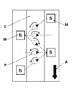
planarised in said two dimensions. As shown in Figure 2 (corresponding to
Figure 5 of EP 2 157
141), the first magnetic-field-generating device described herein comprises a
linear arrangement
of at least three magnets (M) that are positioned in a staggered fashion or in
zigzag formation,
said at least three magnets (M) being on opposite sides of a feedpath where
magnets (M) at the
same side of the feedpath have the same polarity, which is opposed to the
polarity of the
magnet(s) (M) on the opposing side of the feedpath in a staggered fashion. The
arrangement of
the at least three magnets (M) provides a predetermined change of the field
direction as platelet-
shaped magnetic or magnetisable pigment particles (P) in a coating composition
(C) move by the
magnets (direction of movement: arrow (A)). According to one embodiment, the
first magnetic-
field-generating device comprises a) a first magnet and a third magnet on a
first side of a feedpath
and b) a second magnet between the first and third magnets on a second
opposite side of the
feedpath, wherein the first and third magnets have a same polarity and wherein
the second
magnet has a complementary polarity to the first and third magnets. According
to another
embodiment and as shown in Figure 2, the first magnetic-field-generating
device further
comprises a fourth magnets (M) on the same side of the feedpath as the second
magnet, having
the polarity of the second magnet and complementary to the polarity of the
third magnet. As
described in EP 2 157 141 Al, the magnetic-field-generating device can be
either underneath the
layer comprising the platelet-shaped magnetic or magnetisable pigment
particles, or above and
underneath. Alternatively, the first magnetic-field-generating device
described herein comprises
an arrangement of rollers as shown in Figure 9 of EP 2 157 141 Al, i.e. the
first magnetic-field-
generating device described herein comprises two spaced apart wheels having
magnets thereon,
the magnets having the same staggered configuration as those described
hereabove .
[081] Other particularly preferred magnetic-field-generating devices for bi-
axially orienting the
platelet-shaped magnetic or magnetisable pigment particles are of linear
permanent magnet
Halbach arrays, i.e. assemblies comprising a plurality of magnets with
different magnetisation
directions. Detailed description of Halbach permanent magnets was given by
Z.Q. Zhu et D. Howe
(Halbach permanent magnet machines and applications: a review, IEE. Proc.
Electric Power
App!., 2001, 148, p. 299-308). The magnetic field produced by such a Halbach
array has the
properties that it is concentrated on one side while being weakened almost to
zero on the other
side. Typically, linear permanent magnet Halbach arrays comprise one or more
non-magnetic
24
Date Recue/Date Received 2021-04-22
blocks made for example of wood or plastic, in particular plastics known to
exhibit good self-
lubricating properties and wear resistance such as polyacetal (also called
polyoxymethylene,
POM) resins, and magnets such as Neodymium-Iron-Boron (NdFeB) magnets.
[082] Other particularly preferred magnetic-field-generating devices for bi-
axially orienting the
platelet-shaped magnetic or magnetisable pigment particles are spinning
magnets, said magnets
comprising disc-shaped spinning magnets or magnet assemblies that are
essentially magnetised
along their diameter. Suitable spinning magnets or magnet assemblies are
described in US
2007/0172261 Al, said spinning magnets or magnet assemblies generate radially
symmetrical
time-variable magnetic fields, allowing the bi-orientation of platelet-shaped
magnetic or
magnetisable pigment particles of a not yet hardened coating composition.
These magnets or
magnet assemblies are driven by a shaft (or spindle) connected to an external
motor. In a
preferred embodiment, said magnets or magnet assemblies are shaft-free disc-
shaped spinning
magnets or magnet assemblies constrained in a housing made of non-magnetic,
preferably non-
conducting, materials and are driven by one or more magnet-wire coils wound
around the
housing. Optionally, one or more Hall-effect elements are placed along the
housing such that they
are able to detect the magnetic field generated by the spinning magnet or
magnet assembly and
to appropriately address the one or more magnet-wire coils with electric
current. Such spinning
magnets or magnet assemblies simultaneously serve as the rotor of an electric
motor and as
orientation mean for platelet-shaped magnetic of magnetisable pigment
particles of a not yet
hardened coating composition. In this way, it is possible to limit the driving
mechanism of the
device to the strictly necessary parts and to strongly reduce its size. The
magnetic-field-
generating device can be either underneath the layer comprising the platelet-
shaped magnetic or
magnetisable pigment particles or aside said layer. Detailed description of
such devices is given
in the co-pending European patent application 13 195 717.7.
[083] Subsequently to the exposure of the coating composition to the dynamic
magnetic field of
the first magnetic-field-generating device described herein (step b)) and
while the coating
composition is still wet or soft enough so that the platelet-shaped magnetic
or magnetisable
pigment particles therein can be further moved and rotated, the platelet-
shaped magnetic or
magnetisable pigment particles are further mono-axially re-oriented by the use
of the static
magnetic field of a second magnetic-field-generating device described herein
for orienting them
according to a desired orientation pattern (step c)). Said orientation pattern
obtained in step c)
may be any pattern except a random orientation. The desired orientation of the
platelet-shaped
magnetic or magnetisable pigment particles obtained by exposing them to the
static magnetic
field of the second magnetic-field-generating device (step c)) is chosen
according to the end-use
Date Recue/Date Received 2021-04-22
applications. By comprising the platelet-shaped magnetic or magnetisable
pigment particles
described herein, the coating composition is well-suited for use in printing
OEL such as dynamic,
three-dimensional, illusionary, and/or kinematic images by aligning the
pigment particles within
the coating composition with a magnetic field.
[084] A large variety of optical effects OEL for decorative and security
applications can be
produced by various methods disclosed for example in US 6,759,097, EP 2 165
774 Al and EP
1 878 773 B1. OEL known as flip-flop effects (also referred in the art as
switching effect) may be
produced. Flip-flop effects include a first printed portion and a second
printed portion separated
by a transition, wherein pigment particles are aligned parallel to a first
plane in the first portion
and flakes in the second portion are aligned parallel to a second plane.
Methods for producing
flip-flop effects are disclosed for example in EP 1 819 525 B1 and EP 1 819
525 B1. Optical
effects known as rolling-bar effects may also be produced. Rolling-bar effects
show one or more
contrasting bands which appear to move ("roll") as the image is tilted with
respect to the viewing
angle, said optical effects are based on a specific orientation of magnetic or
magnetisable pigment
particles, said pigment particles being aligned in a curving fashion, either
following a convex
curvature (also referred in the art as negative curved orientation) or a
concave curvature (also
referred in the art as positive curved orientation). Methods for producing
rolling-bar effects are
disclosed for example in EP 2 263 806 Al, EP 1 674 282 Bl, EP 2 263 807 Al, WO
2004/007095
A2 and WO 2012/104098 Al. Optical effects known as Venetian-blind effects may
also be
produced. Venetian-blind effects include pigment particles being oriented such
that, along a
specific direction of observation, they give visibility to an underlying
substrate surface, such that
indicia or other features present on or in the substrate surface become
apparent to the observer
while they impede the visibility along another direction of observation.
Methods for producing
Venetian-blind effects are disclosed for example in US 8,025,952 and EP 1 819
525 B1. Optical
effects known as moving-ring effects may also be produced. Moving-ring effects
consists of
optically illusive images of objects such as funnels, cones, bowls, circles,
ellipses, and
hemispheres that appear to move in any x-y direction depending upon the angle
of tilt of said
optical effect layer. Methods for producing moving-ring effects are disclosed
for example in EP 1
710 756 Al, US 8,343,615, EP 2 306 222 Al, EP 2 325 677 A2, WO 2011/092502 A2
and US
2013/084411.
[085] The second magnetic-field-generating device described herein may
comprise a magnetic
plate carrying surface one or more reliefs, engravings or cut-outs. WO
2005/002866 Al and WO
2008/046702 Al are examples for such engraved magnetic plates.
26
Date Recue/Date Received 2021-04-22
[086] The processes for producing the OEL described herein comprise, partially
simultaneously
with step c) or subsequently to step c), a step of hardening (step d)) the
coating composition so
as to fix the platelet-shaped magnetic or magnetisable pigment particles in
their adopted positions
and orientations in a desired pattern to form the OEL, thereby transforming
the coating
composition to a second state. By this fixing, a solid coating or layer is
formed. In the context of
the present invention, when the hardening step d) is performed partially
simultaneously with the
orientation step c), it must be understood that step d) must become effective
after step c) so that
pigment particles orient before complete hardening of the OEL.
[087] The term "hardening" refers to processes including the drying or
solidifying, reacting,
curing, cross-linking or polymerizing the binder components in the applied
coating composition,
including an optionally present cross-linking agent, an optionally present
polymerization initiator,
and optionally present further additives, in such a manner that an essentially
solid material that
adheres to the substrate surface is formed. As mentioned herein, the hardening
step (step d))
may be performed by using different means or processes depending on the binder
material
comprised in the coating composition that also comprises the platelet-shaped
magnetic or
magnetisable pigment particles.
[088] The hardening step generally may be any step that increases the
viscosity of the coating
composition such that a substantially solid material adhering to the
supporting surface is formed.
The hardening step may involve a physical process based on the evaporation of
a volatile
component, such as a solvent, and/or water evaporation (i.e. physical drying).
Herein, hot air,
infrared or a combination of hot air and infrared may be used. Alternatively,
the hardening process
may include a chemical reaction, such as a curing, polymerizing or cross-
linking of the binder and
optional initiator compounds and/or optional cross-linking compounds comprised
in the coating
composition. Such a chemical reaction may be initiated by heat or IR
irradiation as outlined above
for the physical hardening processes, but may preferably include the
initiation of a chemical
reaction by a radiation mechanism including without limitation Ultraviolet-
Visible light radiation
curing (hereafter referred as UV-Vis curing) and electronic beam radiation
curing (E-beam curing);
oxypolymerization (oxidative reticulation, typically induced by a joint action
of oxygen and one or
more catalysts preferably selected from the group consisting of cobalt-
containing catalysts,
vanadium-containing catalysts, zirconium-containing catalysts, bismuth-
containing catalysts and
manganese-containing catalysts); cross-linking reactions or any combination
thereof.
[089] Radiation curing is particularly preferred, and UV-Vis light radiation
curing is even more
preferred, since these technologies advantageously lead to very fast curing
processes and hence
drastically decrease the preparation time of any article comprising the OEL
described herein.
27
Date Recue/Date Received 2021-04-22
Moreover, radiation curing has the advantage of producing an almost
instantaneous increase in
viscosity of the coating composition after exposure to the curing radiation,
thus minimizing any
further movement of the particles. In consequence, any loss of oriention after
the magnetic
orientation step can essentially be avoided. Particularly preferred is
radiation-curing by photo-
polymerization, under the influence of actinic light having a wavelength
component in the UV or
blue part of the electromagnetic spectrum (typically 200 nm to 650 nm; more
preferably 200 nm
to 420 nm). Equipment for UV-visible-curing may comprise a high-power light-
emitting-diode
(LED) lamp, or an arc discharge lamp, such as a medium-pressure mercury arc
(MPMA) or a
metal-vapour arc lamp, as the source of the actinic radiation. The hardening
step (step d)) can be
performed either partially simultaneously with the step c) or subsequently to
the step c). However,
the time from the end of step c) to the beginning of step d) is preferably
relatively short in order to
avoid any de-orientation and loss of information. Typically, the time between
the end of step c)
and the beginning of step d) is less than 1 minute, preferably less than 20
seconds, further
preferably less than 5 seconds, even more preferably less than 1 second. It is
particularly
preferable that there is essentially no time gap between the end of the
orientation step c) and the
beginning of the hardening step d), i.e. that step d) follows immediately
after step c) or already
starts while step c) is still in progress.
[090] If desired, a primer layer may be applied to the substrate prior to the
step a). This may
enhance the quality of the OEL described herein or promote adhesion. Examples
of such primer
layers may be found in WO 2010/058026 A2.
[091] With the aim of increasing the durability through soiling or chemical
resistance and
cleanliness and thus the circulation lifetime of an article, a security
document or a decorative
element or object comprising the OEL described herein, or with the aim of
modifying their
aesthetical appearance (e.g. optical gloss), one or more protective layers may
be applied on top
of the OEL. When present, the one or more protective layers are typically made
of protective
varnishes. These may be transparent or slightly coloured or tinted and may be
more or less
glossy. Protective varnishes may be radiation curable compositions, thermal
drying compositions
or any combination thereof. Preferably, the one or more protective layers are
radiation curable
compositions, more preferable UV-Vis curable compositions. The protective
layers may be
applied after the formation of the OEL in step d).
[092] The OEL described herein may be provided directly on a substrate on
which it shall remain
permanently (such as for banknote applications). Alternatively, an OEL may
also be provided on
a temporary substrate for production purposes, from which the OEL is
subsequently removed.
This may for example facilitate the production of the OEL, particularly while
the binder material is
28
Date Recue/Date Received 2021-04-22
still in its fluid state. Thereafter, after hardening the coating composition
for the production of the
OEL, the temporary substrate may be removed from the OEL. Of course, in such
cases the
coating composition must be in a form that is physically integral after the
hardening step, such as
for instances in cases where a plastic-like or sheet-like material is formed
by the hardening.
Thereby, a film-like transparent and/or translucent material consisting of the
OEL as such (i.e.
essentially consisting of oriented platelet-shaped magnetic or magnetisable
pigment particles
having non-isotropic reflectivity, hardened binder components for fixing the
pigment particles in
their orientation and forming a film-like material, such as a plastic film,
and further optional
components) can be provided.
[093] Alternatively, in another embodiment an adhesive layer may be present on
the OEL or
may be present on the substrate comprising an OEL, said adhesive layer being
on the side of the
substrate opposite the side where the OEL is provided or on the same side as
the OEL and on
top of the OEL. Therefore an adhesive layer may be applied to the OEL or to
the substrate, said
adhesive layer being preferably applied after the hardening step has been
completed. In such
instances, an adhesive label comprising the adhesive layer and the OEL or an
adhesive layer,
the OEL and the substrate as the case may be formed. Such a label may be
attached to all kinds
of documents or other articles or items without printing or other processes
involving machinery
and rather high effort.
[094] Also described herein are optical effect coated substrates (OECs)
comprising one or more
OELs such as those described herein. The OECs described herein may comprise
the substrate
described herein on which the one or more OELs shall remain permanently (such
as for banknote
applications). Alternatively, the OECs described herein may be in the form of
a transfer foil, which
can be applied to a document or to an article in a separate transfer step. For
this purpose, the
substrate is provided with a release coating, on which one or more OELs are
produced as
described herein. One or more adhesive layers may be applied over the so
produced OEL.
[095] According to one embodiment of the present invention, the optical effect
coated substrate
comprises more than one OEL on the substrate described herein, for example it
may comprise
two, three, etc. OELs. The OEC may comprise a first OEL and a second OEL,
wherein both of
them are present on the same side of the substrate or wherein one is present
on one side of the
substrate and the other one is present on the other side of the substrate. If
provided on the same
side of the substrate, the first and the second OELs may be adjacent or not
adjacent to each
other. Additionally or alternatively, one of the OELs may partially or fully
superimpose the other
OEL. The magnetic orientation of the platelet-shaped magnetic or magnetisable
pigment particles
for producing the first OEL and of the platelet-shaped magnetic or
magnetisable pigment particles
29
Date Recue/Date Received 2021-04-22
for producing the second OEL may be performed simultaneously or sequentially,
with or without
intermediate hardening or partial hardening of the binder material.
[096] Also described herein are articles, in particular security documents,
decorative elements
or objects, comprising the OEL produced according to the present invention.
The articles, in
particular security documents, decorative elements or objects, may comprise
more than one (for
example two, three, etc.) OELs produced according to the present invention.
For example, the
article, in particular security document or the decorative element or object,
may comprise a first
OEL and a second OEL, wherein both of them are present on the same side of the
substrate or
wherein one is present on one side of the substrate and the other one is
present on the other side
of the substrate. If provided on the same side of the substrate, the first and
the second OELs may
be adjacent or not adjacent to each other. Additionally or alternatively, one
of the OELs may
partially or fully superimpose the other OEL.
[097] As mentioned hereabove, the OELs produced according to the present
invention may be
used for decorative purposes as well as for protecting and authenticating a
security document.
[098] Typical examples of decorative elements or objects include without
limitation luxury goods,
cosmetic packaging, automotive parts, electronic/electrical appliances,
furniture and fingernail
lacquers.
[099] Security documents include without limitation value documents and value
commercial
goods. Typical example of value documents include without limitation
banknotes, deeds, tickets,
checks, vouchers, fiscal stamps and tax labels, agreements and the like,
identity documents such
as passports, identity cards, visas, driving licenses, bank cards, credit
cards, transactions cards,
access documents or cards, entrance tickets, public transportation tickets or
titles and the like,
preferably banknotes, identity documents, right-conferring documents, driving
licenses and credit
cards. The term "value commercial good" refers to packaging materials, in
particular for cosmetic
articles, nutraceutical articles, pharmaceutical articles, alcohols, tobacco
articles, beverages or
foodstuffs, electrical/electronics articles, fabrics or jewellery, i.e.
articles that shall be protected
against counterfeiting and/or illegal reproduction in order to warrant the
content of the packaging
like for instance genuine drugs. Examples of these packaging materials include
without limitation
labels, such as authentication brand labels, tamper evidence labels and seals.
It is pointed out
that the disclosed substrates, value documents and value commercial goods are
given exclusively
for exemplifying purposes, without restricting the scope of the invention.
Alternatively, the OEL
may be produced onto an auxiliary substrate such as for example a security
thread, security stripe,
a foil, a decal, a window or a label and consequently transferred to a
security document in a
separate step. As mentioned hereabove, the articles described herein, in
particular security
Date Recue/Date Received 2021-04-22
documents, decorative elements or objects, may comprise more than one (for
example two, three,
etc.) OEL produced according to the present invention. In such a case, the
coating composition
described herein may be applied on the substrate surface described herein so
as to form a first
OEL and a second OEL may be applied to said substrate surface in the form of
an auxiliary
substrate such as those described hereabove, wherein the second OEL is
subsequently
transferred to the substrate surface already comprising the first OEL.
Alternatively, a coating
composition such as those described herein may be applied on a first auxiliary
substrate such as
those described hereabove so as to form a first OEL and a coating composition
such as those
described herein may be applied on a second auxiliary substrate such as those
described
hereabove so as to form a second OEL, wherein the first and second OELS are
subsequently
transferred to a substrate surface such as those described herein.
[0100] As mentioned hereabove, the process described herein advantageously
allows the user
to produce OELs with reduced thickness and therefore increased flexibility in
comparison with the
prior art, for example by using small platelet-shaped magnetic or magnetisable
pigment particles
and printing process being for example a rotogravure printing process or a
flexography printing
process. This advantage may be of high importance for the production of
security documents or
articles consisting of multilayer structures. Typical examples of such
multilayer structures include
for example articles, in particular security documents, decorative elements or
objects, comprising
more than one (for example two, three, etc.) OELs produced according to the
present invention
and security threads or stripes that are incorporated into or onto a banknote,
wherein thick security
threads or stripes may cause difficulties during their integration into or
onto a banknote.
[0101] The skilled person can envisage several modifications to the specific
embodiments
described above without departing from the spirit of the present invention.
Such modifications are
encompassed by the present invention.
[0102] The present invention will now be described by way of Examples, which
are however not
intended to limit its scope in any way.
31
Date Recue/Date Received 2021-04-22
EXAMPLES
Table 1
Epoxyacrylate oligomer 36%
Trimethylolpropane triacrylate monomer 13.5%
Tripropyleneglycol diacrylate monomer 20%
Genorad 16 (Rahn) 1%
Aerosil 200 (Evonik) 1%
Speedcure TPO-L (Lambson) 2%
Irgacure 500 (BASF) 6%
Genocure EPD (Rahn) 2%
Tego Foamex N (Evonik) 2%
7-layer optically variable magnetic pigment particles (*) 16.5%
(*) 7-layer gold-to-green platelet¨shaped optically variable magnetic pigment
particles with
particle size d50 = 4.5 p.m and a thickness of about 1 m, obtained from JDS-
Uniphase, Santa
Rosa, CA.
In the following examples 1 and 2, the coating composition described in Table
1 was applied on
a black paper substrate (Gascogne Laminates M-cote 120) by hand screen
printing using a 190
mesh screen so as to form a pattern (35mm x 35mm) having a thickness of about
15 lam .
Example 1
An OEL was obtained by applying the coating composition described in Table 1
on the paper
substrate described hereabove. The platelet¨shaped optically variable magnetic
pigment
particles were oriented in two steps:
i) exposing the not yet hardened coating composition at a distance of 5 mm to
a magnetic-field-
generating device comprising:
a) a nickel-coated NdFeB disk-shaped permanent magnet (M1) (Webcraft GmbH) of
diameter 35 mm and thickness 2 mm, magnetized along its diameter. The magnet
was
placed inside the central cylindrical cavity (diameter: 35.3 mm, depth: 2.3
mm) of a
square shaped housing made of polyoxymethylene (Maagtechnic Daetwyler),
b) a magnet-wire coil (POLYSOL 155 1X0,15mm HG Distrelec AG) wound around the
assembly over a length of 35 mm, in two tight layers. The magnet-wire coil
comprised
a total of 240 turns, and
32
Date Recue/Date Received 2021-04-22
c) a single phase motion controller (MC) (DIODES AH5771) to drive the magnet-
wire
coil. The Hall element of the motion controller was placed in the middle of
the outer
side of the magnet-wire coil.
This magnetic-field-generating device was powered by 4.5V, type 3LR12, battery
(Varta). The
platelet-shaped optically variable magnetic pigment particles were thus bi-
axially oriented such
that their X-Y plane parallel to an imaginary spheroid surface; and
ii) exposing the not yet hardened coating composition obtained under step i)
to the magnetic field
of a magnetic-field-generating device disclosed in Figure 1 of WO 2008/046702
Al. The device
comprised a NdFeB magnetic plate (3 in Figure 1 of WO 2008/046702 Al,
dimensions: 30mm x
18mm x 6 mm, magnetised along its width, supplier: Webcraft AG) and an
engraved magnetic
plate (2 in Figure 1 of WO 2008/046702 Al) placed at a distance of 5 mm from
the NdFeB
magnetic plate. The engraved magnetic plate was made of Plastoferrite (Max
Baermann TX928),
had the dimensions of 38mm x 38mm x 1mm (length x width x height), magnetised
along its height
and carrying an engraving of the letter "A" (5mm height x 0.5mm depth).
The platelet-shaped optically variable magnetic pigment particles were thus
oriented such that
they exhibited the A "letter" and a rolling bar effect (as shown in Fig. 7b of
US 7,047,883 B2)
superimposed onto the spherical effect obtained during the first, bi-axial
orientation step.
The so-obtained magnetic orientation pattern of the platelet-shaped optically
variable pigment
particles was subsequently fixed by exposing the not yet hardened coating
composition during
0.5 seconds to a UV LED (Phoseon Technology LED UV RX FireFlexTM 75x50WC395-
8W).
Photographic images (Lighting: Reflecta LED Videolight RPL49, Objective: AF-S
Micro Nikkor
105 mm 1:2.8 G ED; Camera: Nikon D800, manual exposure, with automatic digital
image
enhancement options disabled for consistency) of the OEL comprising the
oriented platelet¨
shaped optically variable magnetic pigment particles oriented are shown in
Figures 3A-3E. Figure
3A shows the OEL viewed perpendicular to the OEL's surface. Figure 3B shows
the OEL tilted at
300 clock-wise vertically. Figure 3C shows the OEL tilted at 30 counter clock-
wise vertically.
Figure 3D shows the OEL tilted at 30 clock-wise horizontally. Figure 3E shows
the OEL tilted at
30 counter clock-wise horizontally.
In contrast with the OEL obtained using only the device WO 2008/046702 Al
(Figure 1), the
example described herein exhibited a bright reflection that moved in all four
directions upon tilting
(up-down-left-right) along with the "A" letter. Moreover, there was no
apparent graininess in the
OEL produced according to the invention.
33
Date Recue/Date Received 2021-04-22
Example 2
An OEL was obtained by applying the coating composition described in Table 1
on the paper
substrate described hereabove. The platelet¨shaped optically variable magnetic
pigment
particles were oriented in two steps:
i) exposing not yet hardened coating composition (C) to the magnetic field of
a linear Halbach
array depicted in Figure 4. The linear Halbach array comprised 5 NdFeB N42
magnets (M), each
having the dimensions 15mm x 15mm x lOmm (length x width x height,
alternatively magnetised
along their length or their width); the magnets were fixed in the recesses of
a holder made of a
non-magnetic material (not shown in the Figure for clarity), the distance
between each of the
magnets was 2 mm. The substrate (S) carrying the coating composition (C) was
moved back and
forth eight times at a linear speed of 10 cm/s in a direction parallel to the
magnet array, at half the
height of the magnet array and at a 2 mm distance from the surface of the
magnets facing the
sample. The back and forth movement was confined within the magnet assembly.
The platelet-
shaped optically variable magnetic pigment particles were thus oriented such
that both their X-
axis and Y-axis were substantially parallel to the substrate surface; and
ii) exposing the not yet hardened coating composition containing the
platelet¨shaped optically
variable magnetic pigment particles oriented as described in the first step to
the magnetic field of
a same second magnetic-field-generating device described for Example 1 shown
in the Fig. 7c of
US 7,047,883 B2.
The so-obtained magnetic orientation pattern of the platelet-shaped optically
variable pigment
particles led to an OEL exhibiting a rolling bar effect. Said so-obtained
magnetic orientation
pattern was, partially simultaneously with the exposure step to the second
magnetic-field-
generating device (as described in WO 2012/038531 Al), fixed by exposing the
not yet hardened
coating composition during 0.5 seconds to a UV LED (Phoseon Technology LED UV
RX
FireFlex TM 75x50WC395-8W).
The brightness of the so-obtained OEL was quantified by measuring the
lightness at bright area
of greyscale 8-bit photographic images, using a commercially available
software (Adobe
Photoshop C54). The lightness scale was 0 (full black) to 255 (full white).
The greyscale 8-bit
photographic images of the OEL of Example 2 were obtained with the following
settings:
- lighting: Reflecta LED Videolight RPL49, positioned at a 45 angle to the
OEL and at a
distance of 110mm,
- camera: Nikon D800, ISO 800, aperture F/36, speed 1/60s, colour
temperature 5700K,
- objective: AF-S Micro Nikkor 105 mm 1:2.8 G ED, manual focus at 37cm
34
Date Recue/Date Received 2021-04-22
- software - Camera Control Pro 2.14.0 W, automatic digital image
enhancement options
disabled, and
- raw file converted as is (no parameters to be changed) to color TIFF 8-
bit by NXviewer
software supplied with camera.
The so-obtained photographic image of the OEL prepared according to the
present invention is
shown in Figure 5A. For comparative purpose, an OEL obtained using only the
second orientation
step described hereabove was obtained with the same settings as described
hereabove. The
resulting photographic image is shown in Fig. 5B. A dotted line comprising 5
line segments was
drawn inside the bright area of Fig. 5A and 5B. The average lightness of each
segment of the
dotted line was determined and an average value Vb was calculated. This gave
an average
brightness value Vb = 164 for Figure 5a and Vbref = 115 for Figure 5b. The two-
step magnetisation
method described herein resulted therefore in a brightness increase AVb of
42%, the brightness
increase being defined as AVb =(( Vb- Vbref) i Vbref)*100. In Figures 5A and
5B, X represents the
distance between the extremity of the OEL and the centre of the rolling bar
and is 5.5 mm.
Date Recue/Date Received 2021-04-22