Note: Descriptions are shown in the official language in which they were submitted.
METHOD AND APPARATUS FOR ACTUATING A DOVVNHOLE TOOL
BACKGROUND
[0003] This section of this document introduces information from the
art that
may be related to or provide context for some aspects of the technique
described
herein and/or claimed below. It provides background information to facilitate
a
better understanding of that which is disclosed herein. This is a discussion
of
"related" art. That such art is related in no way implies that it is also
"prior" art.
The related art may or may not be prior art. The discussion in this section is
to be
read in this light, and not necessarily as admissions of prior art.
[0004] Oil, gas, and other fluids are extracted from the Earth by
drilling wells
into the ground. Historically, and in the popular imagination these wells were
drilled straight down into the ground--i.e., vertically. In the last few
decades,
however, drilling wells that significantly deviate from the vertical have
become
quite common. For convenience, such wells will be called "horizontal" wells
herein since many of them actually are horizontal to the Earth's surface.
[0005] The process of finishing a well for production of the sought
after fluid
is frequently referred to as "completion". Completion often includes
stimulation,
or 'Tracking", the well to help increase its production. When constructing a
horizontal, multi-stage completion of a hydrocarbon producing well, it is
often
desirable to conduct a casing pressure test prior to
1
CA 2929931 2019-10-23
CA 02929931 2016-05-06
WO 2015/069909 PCT/US2014/064365
beginning the stimulation ("frac") process. The casing must be tested to the
maximum
anticipated treatment pressure. Current hydraulic opening initiator sleeves
(toe shoes) require
that the operator pressure up to their desired casing test pressure and then
over to actually open
the initiator sleeve (Le., 10 ,000 psi test to 11,000 psi opening).
[00061 The presently disclosed technique is directed to resolving, or at
least reducing, one or
all of the problems associated with completion of a well. Even if solutions
are available to the
art to address these issues, the art is always receptive to improvements or
alternative means,
methods and configurations. Thus, there exists a need for a technique such as
that disclosed
herein.
SUMMARY
[0007] In a first aspect, a method for operating a valve in a wellbore
comprises: applying a
first fluid pressure to a bore of the valve; trapping the first fluid pressure
in a portion of the
valve; reducing the pressure in the bore of the valve to a second fluid
pressure, thereby creating a.
pressure differential between the portion of the valve and the bore of the
valve; and opening the
valve responsive to the pressure differential.
100081 In a second aspect, a valve comprises: a valve body defining a bore,
a chamber, and a
fluid passageway, the bore being in fluid communication with the chamber; a
.first piston
disposed in the body to trap a first fluid pressure in the chamber when the
first fluid pressure is
applied to the bore of the body; and a second piston disposed in the body to
open the fluid
passageway in the valve body when a second fluid pressure is applied to the
bore of the body,
wherein the second fluid pressure is less than the first fluid pressure.
(0009) in a third aspect, a method of actuating a downhole tool in a
wellbore, the downhole
tool being actuated by a. valve, comprises: pressuring up the wellbore to a
first fluid pressure;
trapping the first fluid pressure in a portion of the valve; reducing the
pressure in the wellbore to
a second fluid pressure thereby creating a pressure differential within the
valve; opening a fluid
passageway in the valve responsive to the pressure differential; and pumping
fluid through the
opened fluid passageway of the valve to actuate the downhole tool.
2
CA 02929931 2016-05-06
WO 2015/069909 PCT1US2014/064365
100101 The above paragraphs present a simplified summary of the presently
disclosed subject
matter in order to provide a basic understanding of some aspects thereof. The
summary is not an.
exhaustive overview, nor is it intended to identify key or critical elements
to delineate the scope
of the subject matter claimed below. Its sole purpose is to present some
concepts in a simplified
form as a prelude to the more detailed description set forth below,
BRIEF DESCRIPTION OF THE DRAWINGS
[00111 The invention may be understood by reference to the following
description taken in
conjunction with the accompanying drawings, in which like reference numerals
identify like
elements, and in which:
100121 Figure I conceptually depicts a tubular string deployed for downhole
operations.
[00131 Figure 2 conceptually depicts a tubular string deployed for downhole
operations in an
embodiment alternative to that shown in Figure 1.
[00141 Figure 3 depicts a downhole apparatus in accordance with one
particular embodiment
of the presently disclosed technique in a sectioned view.
100151 Figure 4A-Figure 4B, Figure 5A-Figure 5B, and Figure 6-Figure 8
depict portions of
the downhole apparatus of Figure 3 during various stages of operation.
[00161 Figure 9 illustrates the pressure cycling in the wellbore during the
operation of the
downhole apparatus.
100171 Figure 10A-Figure 108 depict a downhole apparatus in accordance with
a second
particular embodiment of the presently disclosed technique in isometric and
sectioned views,
respectively.
100181 Figure HA-Figure 11B, Figure 12A.-Figure 1213, and Figure 13-Figure
15 depict
portions of the downhole apparatus of Figure 10A-Figure 10B during various
stages of operation.
3
CA 02929931 2016-05-06
WO 2015/069909 PCTIUS2014/064365
100191 While the invention is susceptible to various modifications and
alternative forms, the
drawings illustrate specific embodiments herein described in detail by way of
example. It should
be understood, however, that the description herein of specific embodiments is
not. intended to
limit the invention to the particular forms disclosed, but on the contrary,
the intention is to cover
all modifications, equivalents, and alternatives falling within the spirit and
scope of the invention
as defined by the appended claims.
DETAILED DESCRIPTION
100201 Illustrative embodiments of the subject matter claimed below will
now be disclosed.
In the interest of clarity, not all features of an actual implementation are
described in this
specification. It will be appreciated that in the development of any such
actual embodiment,
numerous implementation-specific decisions must be made to achieve the
developers' specific
goals, such as compliance with system-related and business-related
constraints, which will vary
from one implementation to another. Moreover, it will be appreciated that such
a development
effort, even if complex and time-consuming, would be a routine undertaking for
those of
ordinary skill in the art having the benefit of this disclosure.
100211 The presently disclosed technique allows the operator to open a
hydraulically
actuated downhole tool at a predetermined pressure (equal to, greater than, or
less than test
pressure) by allowing the operator to pressure up to his test pressure, bleed
the pressure off and
then reapply pressure to open a sleeve. This is accomplished through a. method
of trapping
pressure and creating a 'pressure differential during the bleed off cycle.
This pressure differential
then shifts the sleeve that exposes a pressure actuating device (e.g., a
rupture disk) to casing
pressure. A reapplication of pressure to the string activates the pressure
actuating device and
allows pressure to act on the shifting sleeve, this shifting sleeve in turn
opens due to its own
created pressure differential exposing stimulation ports in the wall of the
tool housing.
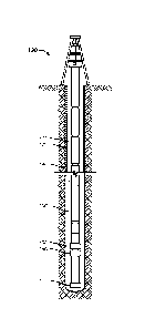
[00221 Turning now to Figure 1, a downhole apparatus 100 is shown deployed
as a part of a
tubular string 110 in a wellbore 120 during a cementing operation .130. The
downhole apparatus
100 may be run on a liner, a casing, tubing or any other string or pressure
bearing pipe lowered
4
CA 02929931 2016-05-06
WO 2015/069909 PCT1US2014/064365
into the well depending on the embodiment. Furthermore, although this
particular embodiment.
is intended for a cementing operation, the presently disclosed approach can be
used in nn-
cemented applications as well. Examples of such un-cemented applications
include, but are not
limited to, open hole implementations.
[0023.1 The wellbore 120 includes a casing 140 that ends at some
predetermined. point above
the bottom of the wellbore 120, and so is an "open hole". The cementing
operation 130 may be
any kind of cementing operation encountered in the art. Those in the art will
appreciate that
cementing operations come in many variations depending on numerous factors
such as the
wellbore design, intended operations upon completion, the constitution of the
formation in which
the well is drilled, and applicable regulations. Accordingly, the embodiments
disclosed herein
are not limiting and are exemplary only. The technique currently disclosed and
claimed is
amenable to all manner of operations and variable to meet these types of
concerns.
[00241 The length and composition of' the tubular string 110 will be highly
implementation
specific and is not material to the practice of the technique. The downhole
apparatus 100 is
disposed in accordance with conventional practice toward the end of the
tubular string 110. The
downhole apparatus 100 may be, for example, three or four joints from the
bottom of the casing
140 or the tubular string 110. The joints below the downhole apparatus 100 may
include but is
not limited to a landing collar 150, a float collar 160, a float shoe 170, or
some combination of
these depending on the embodiment.
10025j The embodiment shown in Figure 1 is a vertical well. However, the
presently
disclosed technique is equally applicable to horizontal wells. This is, in
fact, expected to be the
typical application. A portion of one such horizontal well 200 is shown in
Figure 2. The
horizontal well 200 may be produced by directional drilling or may be the
result of drilling a
deviated well, or some combination of these techniques. The present invention
is indifferent to
the manner in which the well is drilled.
100261 in the description that follows, the terms "upper" or "lower" are
used to identify that
which is closer and farther, or proximal and distal, to and from the wellhead
at the Earth's
surface as traced through the wellbore. This accords with their usage in the
art. The same is true
CA 02929931 2016-05-06
WO 2015/069909 PCT/US2014/064365
for similar terms such as "uphole" and "downhole" when used in such a context.
Thus, in
embodiments where the wellbore is horizontal and the components are not
necessarily "above"
or "below" each other in the sense one might find in a vertical wellbore, they
will still be
proximal or distal to the wellhead through the wellbore and so the terms
"upper", "lower",
"uphole", and "downhole" still apply.
[00271 Figure 3 presents a first particular embodiment of the downhole
apparatus 100 first
shown in Figure 1. In this particular embodiment, the downhole apparatus 100
comprises a
valve 300 and a hydraulically actuated downhole tool 301. The downhole tool
301 is, in this
particular embodiment, a toe valve. The presently disclosed technique admits
wide latitude as to
the implementation of the hydraulically actuated downhole tool. One particular
implementation
of a toe valve will be discussed below, but it is to be understood that the
presently disclosed
technique may be used with any suitable hydraulically actuated downhole tool
known to the art.
[00281 The valve 300 comprises a valve body 302 defining a bore 303 in
fluid
communication with a chamber 304 and a fluid passageway 305. The valve 300
also includes a
first piston 306 and a second piston 307. The first piston 306 is disposed in
the body 302 to trap
a first fluid pressure in the chamber 304 when the first fluid pressure is
applied to the bore 303 of
the body 302. The second piston 307 is disposed in the body 302 to open the
fluid passageway
305 when a second flukl pressure is applied to the bore 303 of the body 302,
wherein the second
fluid pressure is less than the first fluid pressure.
100291 More particularly, the valve body 302 comprises in this embodiment
an upper sub
310, a housing 315, a lower sub 320, and an inner mandrel 325. The housing 315
is
mechanically engaged at either end thereof to the tipper sub 310 and the lower
sub 320. The
mechanical engagement may be by any suitable means known to the art. The
illustrated
embodiment effects the mechanical engagement through mating threads such is
well known and
commonly used throughout the art. However, other suitable means may be
employed in
alternative embodiments. The inner mandrel 325 is disposed within the housing
315 between the
upper sub 310 and the lower sub 320. The inner mandrel 325 abuts the upper sub
310 and the
lower Rib 320 on either end but does not engage them by mating thread, pins,
welds, or any other
such technique in this particular embodiment.
6
CA 02929931 2016-05-06
WO 2015/069909 PCT/US2014/064365
E00301 The inner mandrel 325, in conjunction with the housing 315, defines
the chamber
304. The chamber 304 is in direct fluid communication with the bore 303 and a
first port 345
and indirect fluid communication with a second port 330 and a third port 340
through the bore
304, all in the inner mandrel 325. As is better shown in Figure 4A-Figure 4B,
the first port 345,
second port 330, and third port 340 each comprises at least one radial port
400 (only one
indicated). The number of radial ports 400 is implementation specific and can
range from as low
as one to virtually any higher number. Those in the art having the benefit of
this disclosure will.
appreciate, however, that there are practical considerations in the design of
such a tool that will
mitigate against excessively large numbers of ports. Similarly, the geometry
need not
necessarily be circular and the distribution need not necessarily be uniform
in alternative
embodiments.
10031) Some of the details described herein are implementation specific and
so may see wide
variation across different. embodiments. This includes details such as the fit
of the inner mandrel
325 to the upper sub 310 and the lower sub 320 and the number. Such details
may be employed
to, for example, facilitate manufacture and assembly of the valve 300. This
also includes details
such as the number and distribution of radial ports 400 in the first port 345,
second port 330, and
third port 340. However, other considerations familiar to those in the art, or
even these particular
considerations weighed differently or examined in a different context, might
mitigate for
departure from such details. The presently disclosed technique therefore
admits variation in such
details.
[0032] Returning now to Figure 3, there are two pistons disposed in the
chamber 304 about
the inner mandrel 325, as shown better in Figure 4A-Figure 48. The first
piston 306, shown in
Figure 4A, is a check piston. The second piston 335, shown in Figure 4B,
comprises a lock
piston 360 and a bypass piston 365. The pistons move responsive to fluid
pressure and to control.
fluid pressure within the valve 300 as will be described hereafter.
[00331 The toe valve 301 may be any suitable toe valve known to the art. hi
the illustrated
embodiment, the toe valve 301 is the toe valve disclosed and claimed in U.S.
Application Serial
No. 13/924,828. However, it is to be understood that other suitable toe valves
known to the art
may be used in alternative embodiments. A fuller description of the design,
construction and
7
CA 02929931 2016-05-06
WO 2015/069909 PCT/US2014/064365
operation of the illustrated toe valve 301 can be found in the aforementioned
application. For
present purposes, the toe valve 301 is initiated by fluid pressure through the
fluid passageway
305 to move a sliding sleeve and uncover ports permitting fluid flow from the
bore 303 to the
exterior of the tubular string 110.
[00341 Figure 3 and Figure 4A-figure 4B depict the downhole apparatus 100
as it is run into
the wellbore 120 as shown in Figure .1 or Figure 2. The wellbore 120, shown in
Figure 1, and the
bore 303, shown in Figure 3, at this time are at an ambient pressure, which
will typically be a
hydrostatic pressure resulting from the weight of the fluid in the wellbore
120. The first piston
306 is shown in its open position in Figure 4A. The lock piston 360 of the
second piston 307, as
shown in Figure 4B, is in its locked position. The bypass piston 365 is in its
safe position and is
locked to the inner mandrel 325 by a locking dog 347.
[00351 'The first piston 306 is pinned to the inner mandrel 325 by a shear
pin 440 and the
lock piston 360 is pinned to the inner mandrel 3.25 by a shear pin 442. The
shear pins 440, 442
prevent inadvertent shifting of the first piston 306 and the second piston
307. The shear pins
440, 442 are, by way of example and illustration, but one means by which the
inadvertent
shifting of the first piston 306 and the lock piston 360 may be accomplished.
Other suitable
means are known to the art for performing this function. For example, the
shear pins may be
shear wires, screws, or some other device. Any suitable means known to the art
may be used for
this purpose and alternative embodiments may employ any such suitable means.
10036j The chamber 304 is exposed to the fluid. pressure in the bore 303
through the first port
345 and the aligned port 347 in the first piston 306. Thus, when the downhole
apparatus 100 is
run into the wellbore 120 as a part of the tubular string 110, the pressure in
the chamber 304 is
the ambient pressure in the wellbore 120 and the bore 303. The pressure across
the lock piston
360 is balanced by the application of the fluid pressure in the bore 303
through the second port
330. Note that the third port 340 is closed by the bypass piston 365 and
sealed by the sealing
elements 367, 368.
10037j Once the tubular string 110 is disposed within the wellbore 120, the
wellbore 120 is
pressured up to a first fluid pressure (P,) in accordance with conventional
practice, as is shown
8
CA 02929931 2016-05-06
WO 2015/069909 PCT/US2014/064365
in Figure 9. This will typically be a pan of the casing pressure test, and so
the first fluid pressure
will be the casing test pressure. Those in the art will appreciate that this
test is ordinarily
governed by regulation and that the parameters set for the test by regulation
will vary by the
location of the well.
[00381 These parameters include not only the pressure to which the well
must be brought up
to, but also the time during which it must be held at that pressure. Thus,
even in embodiments in
which the first fluid pressure is the testing pressure, that pressure will
vary depending on the
implementation. Similarly, the time at which the well is held at the first
fluid pressure will also
vary depending on. the implementation. Those in the art having the benefit of
this disclosure will
be able to readily ascertain those parameters for their particular
implementation.
[00391 The chamber 304, because it is in fluid communication with the bore
303. as described
above, will pressure up to the first fluid pressure (PI) along with the rest
of the well. The shear
pin 440 holding the first piston 306 is selected to shear at the first fluid
pressure. When the shear
pin 440 shears as the well pressure reaches the first 'fluid pressure, the
first piston 306 moves to a
closed position as shown in Figure 5A. The first piston 306 may be held in
this closed position
by a locking or latching mechanism 311 to prevent it from moving at this point
in some
embodiments. The movement of the first piston 306 disturbs the alignment
between the first port
345 and the aligned port 347. The first port 345 is then otherwise sealed by
the sealing elements
500, 501.
100401 The movement of the first piston 306 to its closed position thereby
interrupts the fluid
communication between the bore 303 and the chamber 304 through the first port
345. The
second piston 307, however, is still held in position by the second shear pin
442 as is shown in
Figure 5B. The pressure across the lock piston 360 is still balanced through
the second port 330.
The pressure in the bore 303 and the chamber 304 is at the first fluid
pressure at this point in the
operation. As described above, the closure of the first piston 306 seals the
chamber 304 from the
first port 345. The chamber 304 is furthermore sealed on its other end by the
sealing elements
504, 505. Thus, the first fluid pressure is "trapped" within the chamber 304,
i.e., in that portion
of the valve 300.
9
CA 02929931 2016-05-06
WO 2015/069909 PCT/US2014/064365
EOM" The pressure in the wellbore 120 is then brought down to a second
fluid pressure (P2)
less than the first fluid pressure as shown in Figure 9. Turning now to Figure
6, in the illustrated
embodiment, the pressure in the portion 600 of the chamber 304 is bled out
through the second
port 330 as the pressure in the bore 303 is reduced. The portion 603 in which
the first fluid
pressure is trapped, however, is sealed at both ends as described above, and
so remains at the
first fluid pressure. This creates a differential pressure across the lock
piston 360 that shears the
pin 442, thereby permitting the lock piston 360 to stroke downward, which is
to the right in the
drawings, so that the lock piston 360 abuts against the bypass piston 365 as
shown.
[00421 Still referring now to Figure 6, when the lock piston 360 strokes
downward, a recess
550, best shown in Figure 5B, aligns with the locking dog 347. This allows the
locking dog 347
to expand radially into the recess 550 to unlock the bypass piston 365 from
the inner mandrel
32$ and lock the bypass piston 365 to the lock piston 360. The differential
pressure continues to
act on the lock piston 360 while the pressure continues to bleed off through
the second port 330.
The lock piston 360 continues to stroke downward, taking the bypass piston 365
with it through
the engagement provided by the locking dog 347 as shown in Figure 7.
[00431 Still referring to Figure 7, when the second piston 307-1.e., the
lock piston 360 and
bypass piston 365¨finishes the downward stroke, the wellbore 120 and the bore
303 are at the
second fluid pressure. The downward stroke aligns a port 700 in the second
piston 307 with the
third port 340. This opens the valve 300 by permitting fluid communication
from. the bore 303
through the aligned ports 340, 700 and into the fluid passageway 305. Thus,
the valve 300 is
opened responsive to the pressure differential across the lock piston 360 from
the trapped first
fluid pressure when the pressure in the bore 303 is reduced to the second
fluid pressure.
[00441 in the illustrated embodiment, the wellbore 120 is then pressured up
again to a third
fluid pressure (P3.) greater than the second fluid pressure as shown in Figure
9. In the illustrated
embodiment, this third fluid pressure is not as great as the first, but this
may not be true in some
embodiments. The third fluid pressure may be as great or greater than the
first fluid pressure in
some alternative embodiments.
CA 02929931 2016-05-06
WO 2015/069909 PCT/US2014/064365
[0045] The third fluid pressure then acts through the fluid passageway 305
to actuate the toe
valve 301. Note that the actuation of the toe valve 301 will depend to some
degree on the
implementation thereof. In the illustrated embodiment, the third fluid
pressure acts through the
fluid passageway 305 to move the sliding sleeve 706, shown in both Figure 7
and Figure 8. This
moves the sliding sleeve 706 from its closed position partially shown in
Figure 7 to its open
position, shown in Figure 8, to expose the ports 803 (only one indicated) of
the toe valve 301.
This movement, then, opens the toe valve 301 and permits fluid flow through
the bore 303 to the
external annulus surrounding the downhole apparatus 100 in the wellbore 120.
100461 The fluid used to open the toe valve 301 may be any fluid used in
the art in such
circumstances. The pressures at which the toe valve 205 opens will be
implementation specific
depending on operating regulations governing operations on the well. However,
pressures on the
order of 17,000 psi will not be uncommon.,
10047] This particular embodiment also includes a "failsafe" mode of
operation. This mode
of operation could be employed if, for example, some error happens in the
function of the pistons
in a manner that prohibits the delivery of the third fluid pressure through
the fluid passageway
305. The fluid passageway 305 is protected by a pressure barrier 806, shown in
Figure 8, which
will permit fluid communication with the bore 303 directly from the bore 303.
Should the
intended operation of the valve 300 described above go awry, the well operator
can circumvent it
by pressuring up the wellbore 120 to a suitably high fourth fluid pressure
that will cause the
pressure banier 806 to give way. This will then permit fluid flow into the
second port 330 and
delivery of the fourth pressure to the toe valve 301. However, some
embodiments may omit this
feature.
[00481 in the illustrated embodiment, the valve '300 and the toe valve 301
are manufactured
as separate tools that are assembled prior to use. Alternative embodiments,
however, may
manufacture the features of each in a single tool for assembly into a suing.
This true also even in
embodiments in which the hydraulically actuated downhole tool is a tool other
than a toe valve.
Other, similar variations may become apparent to those ordinarily skilled in
the art having the
benefit of this disclosure.
CA 02929931 2016-05-06
WO 2015/069909 PCT1US2014/064365
100491 The presently disclosed technique admits variation in the design of
the valve 300 in
alternative embodiments. One such alternative embodiment is shown in Figure
10A and Figure
1013 in an isometric and a sectioned view, respectively. The downhole
apparatus 100 comprises,
in this particular embodiment, and valve 1000 and a hydraulically actuated
downhole tool, which
in this particular embodiment is the toe valve 301 discussed above.
[00501 Referring now to Figure 10A, the valve 1000 comprises an upper sub
1010, an upper
housing 1015, and a lower sub 1020. The housing 1015 is mechanically engaged
at either end
thereof to the upper sub 1010 and the lower sub 1020. The mechanical
engagement may be by
any suitable means known to the art. The illustrated embodiment effects the
mechanical.
engagement through mating threads such is well known and commonly used
throughout the art
However, other suitable means maybe employed in alternative embodiments.
[00511 As shown in Figure 1013, the valve 1000 also includes an inner
mandrel 1025
disposed within the upper housing 1015 between the upper sub 1010 and the
lower sub 1020.
The inner mandrel 102$ abuts the upper sub 1010 and the lower sub 1020 on
either end but. does
not engage them by mating thread, pins, welds, or any other such technique in
this particular
embodiment. The inner mandrel 1025 in this particular embodiment also
comprises an upper
inner mandrel 1030 and a lower inner mandrel 1035 that are mechanically
engaged through
mating threads.
[00521 The inner mandrel 1025, in conjunction with the upper housing 1015,
defines a
chamber 1040. The chamber 1040 is in fluid communication with the bore 1048
through a first
port 1045 in the upper sub 1010. As better shown in Figure 11A, the first port
1045 comprises a
radial port 1100 and an axial port 1105. To facilitate manufacturing, the
first port 1045 extends
through the wall of the upper sub 1010 but, prior to use, is sealably plugged
on the outside by the
plug 1101. Note that there are in fact two first ports 1045 in this particular
embodiment.
[00531 The chamber 1040 is also, at various times during the operation of
the valve 1000, in
fluid communication with the bore 1048 through a second port 1047. Each second
port 1047
comprises a radial port through the inner mandrel 1025,
12
CA 02929931 2016-05-06
WO 2015/069909 PCT/US2014/064365
100541 The third port 1050 is better shown in Figure 11B and comprises, in
this particular
embodiment, a radial port 1109. The third port 1050 is in fluid communications
with a fluid
passageway 1051 comprised of two axial ports 1110, 1115. The fluid passageway
1051 is
protected. by a pressure barrier 1120, such as a rupture disk, a check valve,
or a pressure relief
valve between the two axial ports 1110, 1115. The pressure barrier 1120, when
intact, seals the
axial ports 1110, 1115 from one another, hut when overcome, the axial ports
1110, 1115 are in
fluid i..,ommunication.
100551 Still referring to Figure 1113, the inner mandrel 1025 defines a
first set 1125 and a
second set 1.130 of radial ports 1135 (only one indicated). These radial ports
1135 comprise the
second port 1047 and the third port 1050 in this particular embodiment. The
number of radial
parts 1135 in each of the sets 1125, 1130 is implementation specific and can
range from as low
as one to virtually any higher number. Those in the art having the benefit of
this disclosure will
appreciate, however, that there are practical considerations in the design of
such a tool that will
mitigate against excessively large numbers of ports. Similarly, the geometry
need not
necessarily be circular and the distribution need not necessarily be uniform
in alternative
embodiments.
[00561 Returning now to Figure 10B, a first piston 1055 and a second piston
1002 are
disposed in the chamber 1040 about the inner mandrel 1025. The first piston
1055 is again a.
check piston and is disposed about the upper inner mandrel 1030. The second
piston 1002
comprises a lock piston 1060 and a bypass piston 1065, both of which are
disposed about the
lower inner mandrel 1035. The pistons move responsive to fluid pressure and to
control fluid
pressure as will be described hereafter.
[0057.1 Figure 10A-Figure 1013 depict the downhole apparatus 100 as it is
run into the
wellbore 120 as shown in Figure 1 or Figure 2. The wellbore 120, shown in
Figure 1, and the
bore 1048, shown in Figure 10B, at this time are at an ambient pressure, which
will typically be a
hydrostatic pressure resulting from the weight of the fluid in the wellbore.
The check piston
1055 is shown in its open position in Figure 11A. Note that. the check piston
1055 is pinned to
the inner mandrel 1025 by a shear pin 1.140 to prevent inadvertent shifting.
The lock piston
1060, as shown in Figure 1113, is in its locked position and also pinned to
the inner mandrel 1025
13
CA 02929931 2016-05-06
WO 2015/069909 PCT/US2014/064365
to prevent inadvertent shifting by a shear pin 1142. Still referring to Figure
11B, the bypass
piston 1065 is in its safe position. Its position is held relative o the inner
mandrel 1025 by a
locking dog 1145.
100581 The
check piston 1055 does not seal the chamber 1040 in the position shown in.
Figure HA. The Chamber 1040 is therefore exposed to the fluid pressure in the
bore 1048
through the first port 1045. Thus, when the downhole apparatus 100 is run into
the wellbore 120
as a part of the tubular string 110, the pressure in the chamber 1040 is the
ambient pressure in the
wellbore 120 and the bore 1048.
100591 Once
the tubular string 110 is disposed within the wellbore 120, the wellbore 120
is
pressured up to a first fluid pressure (Pa) in accordance with conventional
practice, as is shown
in Figure 9. The chamber 1040, because it is in fluid communication with the
bore 1048, will
pressure up to the first fluid pressure along with the rest of the well. The
shear pin .1140 holding
the check piston 1055 is selected to shear at the first fluid pressure. When
the shear pin 1140
shears as the well pressure reaches the first. fluid pressure, the check
piston 1055 moves to a
closed position as shown in Figure 12A. The lock piston 1060 and the bypass
piston 1065 do not
shift because they are still pinned or locked to the inner mandrel 1025.
100601 The
sealing elements 1200, 1205, 1207---elastomeric 0-rings, in this particular
embodiment ............................................................. seal
the portion 1056 of the chamber 1040 below the check piston 1055 from that
portion 1215 above the check piston 1055. in particular, they seal against the
face of the check
piston 1055. Thus, whereas fluid flow was previously permitted between the
bore 1048 and the
chamber 1040 around the check piston 1055, such fluid flow is sealed by the
downward
movement of the check piston 1055 to seal the chamber 1040 below the check
piston 1055 from
the bore .1048. The portion 1056 is sealed below by the sealing elements
12.15, 1220, shown in
Figure 12B---again, elastomeric 0-rings in this embodiment. The pressure in
the portion 1056 is
thereby sealed at the first fluid pressure such that the first fluid pressure
is trapped in the portion
1056 as it is isolated by the downward movement of the check piston 1055. Note
that, as shown
in Figure 128, the lock piston 1060 and the bypass piston 1065 are in their
locked position and
safe position, respectively.
14
CA 02929931 2016-05-06
WO 2015/069909 PCT/US2014/064365
100611 The pressure in the wellbore 120 is then brought down to a second
pressure less than
the first fluid pressure. .111 the illustrated embodiment, the pressure in the
portion 1225 of the
chamber 1040 is bled out through second port 1050. The portion 1056, however,
is sealed at
both ends as described above, and so remains at the first fluid pressure. This
creates a
differential pressure across the lock piston 1060 that shears the pin 1142,
thereby permitting the
lock piston 1060 to stroke downward, which is to the right in the drawings, as
shown in Figure
.1.3.
10062] Referring now to both Figure 128 and Figure 13, when the lock piston
1060 strokes
downward, a recess 1250, best shown in Figure 1213, aligns with the locking
dog 1145. This
allows the locking dog 1145 to expand radially into the recess 1250 to unlock
the bypass piston
1065 from the inner mandrel 1025 and lock the bypass piston 1065 to the lock
piston 1060. The
differential pressure continues to act on the lock piston 1060 while the
pressure continues to
bleed off -through the second port 1047. The lock piston 1060 continues to
stroke downward,
taking the bypass piston 1065 with it through the engagement provided by the
locking dog 1145.
When the lock piston 1060 and bypass piston 1065 finish the downward stroke,
as shown in
Figure 14, a plurality of ports 1400 therein align with the radial ports 1135
of the third port 1050
in the inner mandrel 1025. This opens the fluid passageway 1051 to fluid flow
from the bore
1048.
[00631 The wellbore 120 is then pressured up again to a third fluid
pressure greater than the
second pressure as shown in Figure 9. Referring now to both Figure 14 and
Figure 15, the
pressure at this point is communicated from the bore 1058 to the third port
1050 through the
second set 1020 of radial ports 1.135 in the inner mandrel 1025 and the
aligned ports 1400 in the
bypass piston 1065. As mentioned above, the third port 1050 is protected by a
pressure barrier
1100, Which. is a burst disk in this particular embodiment. The pressure
barrier 1120 is
preselected to give way at the third fluid pressure. When the pressure harrier
1120 gives way, the
third fluid pressure is then applied to the sliding sleeve 1070 of the toe
valve 301. The sliding
sleeve 1070 then moves front its closed position, shown partially in Figure
14, to its open
position, shown in Figure 15, to expose the ports 1075 of the toe valve. 301.
[0064] This particular embodiment also includes a "failsafe" mode of
operation in the same
manner as the embodiment of Figure 3A-Figure 8. The third port 1050 is
protected by a second
pressure barrier 1505, shown in Figure 15, which will permit fluid
communication with the bore
1048 via a second path. The well operator can pressure up the wellbore 120 to
a suitably high
fourth pressure that will cause the pressure barrier 1505 to give way and
permit fluid flow to the
toe valve 301.
[0065] The illustrated embodiment may include a shroud 1080, shown only
in Figure 10A.
The shroud 1080 covers the ports of the toe valve 301 during deployment and
operations to help
prevent the ports 1075 from fouling and manage pressures in the bore 303. The
shroud 380 can be
designed to fall away during operations upon experiencing some particular
pressure. For example,
in one embodiment, the shroud 380 breaks upon opening the toe valve 301 and
applying a
breakdown pressure to the shroud 380, the cement, and the formation. Again,
some embodiments
may omit this feature.
[0066] Other non-limiting similarities to the embodiment of Figure 3A-
Figure 8 may also
be found. For example, although the valve 1000 and the toe valve 301 are
manufactured as separate
tools and assembled prior to use, alternative embodiments, however, may
manufacture the features
of each in a single tool for assembly into a string. Other, similar variations
may become apparent
to those ordinarily skilled in the art having the benefit of this disclosure.
[0067] This concludes the detailed description. The particular
embodiments disclosed
above are illustrative only, as the invention may be modified and practiced in
different but
equivalent manners apparent to those skilled in the art having the benefit of
the teachings herein.
Furthermore, no limitations are intended to the details of construction or
design herein shown,
other than as described in the claims below. It is therefore evident that the
particular embodiments
disclosed above may be altered or modified and all such variations are
considered within the scope
and spirit of the invention. Accordingly, the protection sought herein is as
set forth in the claims
below.
16
Date Recue/Date Received 2021-01-25