Language selection

Search

Patent 2929964 Summary

Third-party information liability

Some of the information on this Web page has been provided by external sources. The Government of Canada is not responsible for the accuracy, reliability or currency of the information supplied by external sources. Users wishing to rely upon this information should consult directly with the source of the information. Content provided by external sources is not subject to official languages, privacy and accessibility requirements.

Claims and Abstract availability

Any discrepancies in the text and image of the Claims and Abstract are due to differing posting times. Text of the Claims and Abstract are posted:

  • At the time the application is open to public inspection;
  • At the time of issue of the patent (grant).
(12) Patent: (11) CA 2929964
(54) English Title: BRIDGE SYSTEM FOR MULTI-STAGE WALLS
(54) French Title: SYSTEME DE RACCORDEMENT POUR MURS EN GRADINS
Status: Granted and Issued
Bibliographic Data
(51) International Patent Classification (IPC):
  • E02D 29/02 (2006.01)
  • E04B 02/18 (2006.01)
  • E04B 02/44 (2006.01)
  • E04C 05/16 (2006.01)
(72) Inventors :
  • DEAN, PATRICK E. (United States of America)
  • CURRY, DANIEL J. (United States of America)
  • KEMPAINEN, MATTHEW J. (United States of America)
  • MOUA, KONG CHENG (United States of America)
  • STONEBURNER, MICHAEL (United States of America)
  • SYLVESTRE, DANIEL (United States of America)
(73) Owners :
  • DEAN HOLDING CORPORATION
(71) Applicants :
  • DEAN HOLDING CORPORATION (United States of America)
(74) Agent: PIASETZKI NENNIGER KVAS LLP
(74) Associate agent:
(45) Issued: 2022-08-09
(86) PCT Filing Date: 2014-12-06
(87) Open to Public Inspection: 2015-06-11
Examination requested: 2019-11-05
Availability of licence: N/A
Dedicated to the Public: N/A
(25) Language of filing: English

Patent Cooperation Treaty (PCT): Yes
(86) PCT Filing Number: PCT/US2014/068965
(87) International Publication Number: US2014068965
(85) National Entry: 2016-05-06

(30) Application Priority Data:
Application No. Country/Territory Date
61/913,278 (United States of America) 2013-12-07

Abstracts

English Abstract

A bridge to construct a multi-stage wall is provided with a clip at each end. One of the clips is sized and shaped to fit snugly onto the wall of a standard concrete masonry unit (CMU), while the other is sized and shaped to fit onto a segmental wall system (SWS) unit. A retaining or stand-alone wall is constructed by laying a row of SWS units and a row of CMUs roughly parallel to each other, with bridges extending between them to fix the units. The hollow spaces in each unit and the space between the rows is filled with gravel, rock or other fill material as each course is laid. Additional courses of SWS units and CMUs are placed on top of the prior courses, with bridges added to each course. This process is repeated until the desired wall height is reached. Various sized and shaped clips and connector brackets are provided to allow spacing of the walls at different distances, with varying blocks. Multiple walls can be constructed in parallel and connected with bridges to provide sufficient retention mass for taller walls.


French Abstract

Cette invention concerne un raccord conçu pour construire un mur en gradins, comprenant un crochet à chaque extrémité. Un des crochets est dimensionné et formé de manière à s'adapter de manière serrée sur le mur d'une unité de maçonnerie en béton standard (CMU) tandis que l'autre crochet est dimensionné et formé de manière à s'adapter sur une unité de système de mur à segments (SWS). Un mur de soutènement ou autoporteur est construit par pose d'une rangée d'unités SWS et d'une rangée d'unités CMU de manière approximativement parallèle, des raccords s'étendant entre celles-ci pour fixer les unités les unes aux autres. Les espaces creux dans chaque unité et l'espace séparant les rangées est rempli de gravier, de roche ou autre matériau de remplissage à mesure que chaque rangée est posée. Des rangées supplémentaires d'unités SWS et CMU sont disposées au-dessus des rangées précédentes, des raccords étant ajoutés à chaque rangée. Ce procédé est répété jusqu'à ce que la hauteur de mur voulue soit atteinte. Des crochets et supports de connexion de diverses formes et dimensions sont utilisés pour permettre l'espacement des murs à des distances différentes, au moyen de blocs variés. Plusieurs murs peuvent être construits parallèlement et reliés par des raccords pour assurer une masse de soutènement suffisante pour des murs de plus grande hauteur.

Claims

Note: Claims are shown in the official language in which they were submitted.


THE EMBODIMENTS OF THE INVENTION IN WHICH AN EXCLUSIVE PROPERTY
OR PRIVILEGE IS CLAIMED ARE DEFINED AS FOLLOWS:
1. A multi-stage wall comprising:
a plurality of first blocks arranged to form a first wall, each first block
having
a top and a first side wall defining a side surface thereof;
a plurality of second blocks arranged to form a second wall, each second
block having a first side wall defining a side surface thereof;
a plurality of bridges, each bridge having a height and a top and comprising
a first clip snugly fit onto the first side wall of one of the first blocks, a
second clip
snugly fit onto the first side wall of an adjacent one of the second blocks,
and a
bridge body, which bridge body includes a bridge body connector, connecting
the
first and second clips and fixing the distances between them, wherein the
bridge
body and at least one of the first and second clips, are formed separately
from
each other, and wherein when the first or second clip is fit onto the first
side wall of
a respective first or second block, the bridge body connector is spaced
outwardly
from the side surface of the respective first or second block, and wherein the
bridge body includes a clip connector, wherein the bridge body connector and
the
clip connector are secured together at a location outwardly of the side
surface of
the first side wall of the second block; and
fill between the first and second walls;
wherein the first blocks are taller than the second blocks, and further
comprising a groove formed in the first side wall of each first block, the
height of
the bridges being such that when positioned with the first clip in the groove
in one
of the first blocks and the second clip on one of the second blocks, the top
of the
bridge vertically aligns with the tops of the first blocks; and
wherein each second block has a second side wall on a side thereof
opposite the first side wall thereof, the multi-stage wall further comprising
a
stand-alone clip snugly fit onto the second side wall of each of the second
blocks,
the stand-alone clip having a top and a height such that the top of the stand-
alone
clip vertically aligns with the tops of the first blocks.
12

2. A multi-stage dry construction retaining wall, comprising:
a plurality of first blocks arranged to form a first wall, each first block
having
a height, a top, a bottom opposite the top and a first side wall extending
between
the top and the bottom on a side thereof;
a plurality of second blocks arranged to form a second wall, each second
block having a height, a top, a bottom opposite the top and a first side wall
extending between the top and bottom on a side thereof, wherein the height of
the
first blocks is greater than the height of the second blocks; and
a plurality of bridges, each bridge comprising a first clip snugly fit onto
the
top or bottom of the first side wall of one of the first blocks, a second clip
snugly fit
onto the top or bottom of the first side wall of an adjacent one of the second
blocks, and a bridge body connecting the clips and fixing the distance between
them; and
fill between the first and second walls;
wherein the first side wall of at least the first block includes an inner
surface
which at least in part defines a hollow interior of the first block, and
wherein the
first block includes a groove at the top or bottom of the first side wall that
extends
between an outer surface of the first side wall and the inner surface of the
first
side wall, and wherein the first clip engages the inner and outer surfaces of
the
first side wall of the first block and is positioned within the groove,
wherein the
height of the bridge is such that when positioned with the first clip in the
groove
and the second clip on the adjacent second block, the top of the bridge
vertically
aligns with the tops of the first blocks; and
wherein at least one of the plurality of first blocks forming the first wall
and
the plurality of the second blocks forming the second wall are stacked in
courses
without the use of mortar between adjacent courses.
3. The multi-stage dry construction retaining wall of claim 2, wherein the
second side wall of each second block extends between the top and bottom on a
side thereof opposite its first side wall, the multi-stage wall further
comprising a
stand-alone clip snugly fit onto the second side wall of each of the second
blocks,
the stand-alone clip height being such that the top of the stand-alone clip
vertically
13

aligns with the top of the first blocks.
4. The multi-stage dry construction retaining wall of claim 2, wherein the
second side wall of each second block extends between the top and bottom on a
side thereof opposite its first side wall, the multi-stage wall further
comprising:
a third plurality of blocks arranged to form a third wall, each third block
having a height, a top, a bottom opposite the top and a side wall extending
between the top and bottom on a side thereof, the third wall being positioned
on
the opposite side of the second wall from the first wall;
a second plurality of bridges, each bridge of the second plurality comprising
a third clip snugly fit onto top or bottom of the second side wall of one of
the
second blocks, a fourth clip snugly fit onto the top or bottom of the side
wall of one
of the third blocks, and a bridge body connected the third and fourth clips
and
fixing the distance between the second and third walls; and
fill between the second and third walls.
5. The multi-stage dry construction retaining wall of claim 2, wherein each
first
block further comprises a third side wall extending between the top and bottom
of
the block on a side thereof and each second block further comprises a fourth
side
wall extending between the top and bottom of the block on a side thereof, the
third
and fourth side walls being exposed, so that the wall is a stand-alone wall.
6. A multi-stage dry constriction retaining wall, comprising:
a plurality of first blocks arranged to form a first wall, each first block
having
a height, a top, a bottom opposite the top and a first side wall extending
between
the top and the bottom on a side thereof;
a plurality of second blocks arranged to form a second wall, each second
block having a height, a top, a bottom opposite the top and a first side wall
extending between the top and bottom on a side thereof;
a plurality of bridges, each bridge comprising a first clip snugly fit onto
the
top or bottom of the first side wall of one of the first blocks, a second clip
snugly fit
onto the top or bottom of the first side wall of an adjacent one of the second
14

blocks, and a bridge body connecting the clips and fixing the distance between
them; and
fill between the first and second walls;
wherein the plurality of first blocks forming the first wall and the plurality
of
second blocks forming the second wall are stacked in courses without the use
of
mortar between adjacent courses; and
wherein the height of the first blocks is greater than the height of the
second blocks, and further comprising a groove formed in the first side wall
of
each first block and each first clip is positioned onto the first side wall of
the first
block within the groove, the height of the bridges being such that when
positioned
with the first clip in the groove in one of the first blocks and the second
clip on one
of these second blocks, the top of the bridge vertically aligns with the top
of the
first blocks.
7. The multi-stage dry construction retaining wall of claim 6, wherein each
second block has a second side wall extending between the top and bottom on a
side thereof opposite its first side wall, the multi-stage wall further
comprising a
stand-alone clip snugly fit onto the second side wall of each of the second
blocks,
the stand-alone clip height being such that the top of the stand-alone clip
vertically
aligns with the top of the first blocks.
8. A bridge system for a multi-stage wall, comprising:
a plurality of first blocks arranged to form a first wall, each of the first
blocks
having first and second spaced apart side walls defining a hollow core
therebetween, wherein the first side wall of each of the first blocks defines
an
inner surface of the first wall and wherein the second side wall of each of
the first
blocks defines an outer surface of the first wall;
a plurality of second blocks arranged to form a second wall, each of the
second blocks having first and second spaced apart side walls defining a
hollow
core therebetween, wherein the first side wall of each of the second blocks
defines
an inner surface of the second wall and wherein the second side wall of each
of
the second blocks defines an outer surface of the second wall;

a plurality of bridges connected between the first and second blocks,
wherein each bridge has a bridge body and two ends;
a first clip contiguous to one end of the bridge body, the first clip being
shaped to snugly fit onto the first side wall of the first block, wherein the
first clip
overlies a top surface of the first side wall of the first block between the
core and
the inner surface of the first wall; and
a second clip contiguous to the other end of the bridge body, the second
clip being shaped to snugly fit onto the first side wall of the second block,
wherein
the second clip overlies a top surface of the first side wall of the second
block
between the core and the inner surface of the second wall;
wherein the first blocks are taller than the second blocks, at least one
groove is formed in the top surface of the first side wall of the first blocks
in which
the first clip is positioned when the first clip is snugly fit onto the first
side wall of
the first block, and wherein the height of the bridge and blocks are such
that, with
the bridge in place, the tops of the second clips will align vertically with
the first
side wall of the first blocks.
9. The bridge system of claim 8, wherein the bridge body further comprises
a
connector on at least one of its ends, and wherein at least one of the clips
is
shaped to mount to the bridge body using the connector.
10. The bridge system of claim 9, further comprising a plurality of clips,
each
shaped to fit over the side wall of differently shaped blocks, and each shaped
to
mount to the bridge body using the connector.
11. The bridge system of claim 9, further comprising a connector receiver
bracket shaped to mount to the connectors on two bridge bodies to form an
extended bridge body.
12. The bridge system of claim 11, wherein both ends of each bridge body
have one of the connectors, such that multiple connector receiver brackets can
be
connected to multiple bridge bodies in series to form a further extended
bridge
16

body.
13. The bridge system of claim 11, further comprising bridge bodies in
various
lengths, such that the extended bridge body can be of various lengths.
14. The bridge system of claim 9, wherein the connector comprises a main
body which is semicircular in cross-section with flat surfaces on a base of
the
semicircle, and at least one of the first and second clips has a similarly
shaped
recess which can fit around the connector to hold the clip into position on
the
bridge body.
15. The bridge system of claim 8, wherein the bridge is formed of a
material
selected from the group consisting of polymers, fiberglass reinforced
polymers,
metals and ceramics.
16. The bridge system of claim 8, further comprising a standalone clip
having a
top and a height shaped to snugly fit onto the second side wall of the second
block, the height of the standalone clip being such that, with the bridge in
place
and the standalone clip in place, the top of each standalone clip on the
second
side wall of each second block will align vertically with the first side wall
of each
first block.
17. A multi-stage wall with a bridge assembly, comprising:
a plurality of first blocks arranged to form a first wall, each first block
having
first and second spaced apart side walls defining a hollow core therebetween,
wherein the first side wall of each of the first blocks defines an inner
surface of the
first wall and wherein the second side wall of each of the first blocks
defines an
outer surface of the first wall, and comprising a groove formed in the first
side wall
of each first block;
a plurality of second blocks arranged to form a second wall, each second
block having first and second spaced apart side walls defining a hollow core
therebetween, wherein the first side wall of each of the second blocks defines
an
17

inner surface of the second wall and wherein the second side wall of each of
the
second blocks defines an outer surface of the second wall, and wherein the
first
blocks are taller than the second blocks;
fill between the first and second walls;
a first clip formed to fit snugly onto the first side wall of one of the first
blocks, a second clip formed to fit snugly onto the first side wall of an
adjacent one
of the second blocks, and a bridge body, which bridge body includes a bridge
connector, connecting the first and second clips and fixing the distances
between
them, wherein the bridge body and at least one of the first and second clips
are
formed separately from each other, and wherein when the first or second clip
is fit
onto the side wall of a respective first or second block, the bridge connector
is
spaced outward from the side surface of the respective first or second block,
wherein the bridge has a height and the height of the bridge is such that when
the
bridge is positioned with the first clip thereof in the groove of the first
side wall of
the first block and the second clip thereof on the first side wall of the
second block,
the top of the bridge vertically aligns with the tops of the first blocks; and
a third clip formed to fit snugly onto the second side wall of one of the
second blocks, the third clip having a height being such that when the third
clip is
positioned on the second side wall of one of the second blocks, the top of the
third
clip vertically aligns with the tops of the first blocks.
18. A bridge assembly for a multi-stage dry construction retaining wall,
comprising:
a plurality of first blocks arranged to form a first wall by being stacked in
courses without the use of mortar between adjacent courses, each first block
having a height, a top, a bottom opposite the top and a first side wall
extending
between the top and bottom on a side thereof, wherein the first side wall of
each
first block includes an inner surface which at least in part defines a hollow
interior
of the first block, and wherein each first block includes a groove at the top
or
bottom of the first side wall that extends between an outer surface of the
first side
wall and the inner surface of the first side wall;
a plurality of second blocks arranged to form a second wall adjacent to the
18

first wall, each second block having a height, a top, a bottom opposite the
top and
a first side wall extending between the top and bottom on a side thereof,
wherein
the height of the first blocks is greater than the height of the second
blocks; and
fill between the first and second walls;
a first clip formed to snugly fit onto the top or bottom of the first side
wall of
one of the first blocks, a second clip formed to snugly fit onto the top or
bottom of
the first side wall of an adjacent one of the second blocks, and a bridge body
connecting the clips and fixing the distance between them;
wherein the bridge body further comprises a connector, and wherein at
least one of the clips is shaped to mount to the bridge body using the
connector;
and
wherein the height of the bridge is such that when positioned with the first
clip positioned in the groove of the first side wall of the first block, the
top of the
bridge vertically aligns with the top of the first block.
19. The bridge assembly of claim 18, wherein each second block has a second
side wall extending between the top and bottom on a side thereof opposite its
first
side wall, and wherein the bridge assembly further comprises a stand-alone
clip
snugly fit onto the second side wall of the second block, the stand-alone clip
height being such that the top of the stand-alone clip vertically aligns with
the top
of the first block.
20. A bridge system for a multi-stage wall, comprising:
a plurality of first blocks arranged to form a first wall, each of the first
blocks
having first and second spaced apart side walls defining a hollow core
therebetween, wherein the first side wall of each of the first blocks defines
an
inner surface of the first wall and wherein the second side wall of each of
the first
blocks defines an outer surface of the first wall;
a plurality of second blocks arranged to form a second wall, each of the
second blocks having first and second spaced apart side walls defining a
hollow
core therebetween, wherein the first side wall of each of the second blocks
defines
an inner surface of the second wall and wherein the second side wall of each
of
19

the second blocks defines an outer surface of the second wall; and
a plurality of bridges connected between the first and second blocks,
wherein each bridge has a bridge body and two ends;
a first clip contiguous to one end of the bridge body, the first clip being
shaped to snugly fit onto the first side wall of the first block, wherein the
first clip
overlies a top surface of the first side wall of the first block between the
core and
the inner surface of the first wall; and
a second clip contiguous to the other end of the bridge body, the second
clip being shaped to snugly fit onto the first side wall of the second block,
wherein
the second clip overlies a top surface of the first side wall of the second
block
between the core and the inner surface of the second wall;
wherein the bridge body further comprises a connector on at least one of its
ends, and wherein at least one of the clips is shaped to mount to the bridge
body
using, the connector;
wherein at least one groove is forming in the top surface of the first side
wall of the first blocks and at least one groove is formed in the top surface
of the
first side wall of the second blocks; and
wherein the height of the bridge and blocks are such that, with the bridge in
place, the tops of the first side walls of the second blocks will align
vertically with
the tops of the first side walls of the first blocks.
21. The bridge system of claim 20, wherein at least one of the first clips
or the
second clips is shaped to fit over the side wall of differently shaped blocks
and to
mount to the bridge body using the connector.
22. The bridge system of claim 20, further comprising a connector receiver
bracket shaped to mount to the connectors on two bridge bodies to form an
extended bridge body.
23. The bridge system of claim 22, wherein both ends of each bridge body
have one of the connectors, such that multiple connector receiver brackets can
be
connected to multiple bridge bodies in series to form a further extended
bridge

body.
24. The bridge system of claim 22, further comprising bridge bodies in
various
lengths, such that the extended bridge body can be of various lengths.
25. The bridge system of claim 20, wherein the connector comprises a main
body which is semicircular in cross-section with flat surfaces on the base of
the
semicircle, and at least one of the first and second clips has a similarly
shaped
recess which can fit around the connector to hold the clip into position on
the
bridge body.
26. A method for building a multistage wall comprising:
providing a plurality of first blocks, each of the first blocks having first
and
second spaced apart side walls defining a hollow core therebetween and at
least
one groove is formed in a top surface of the first side wall of the first
blocks;
providing a plurality of second blocks, each of the second blocks having
first and second spaced apart side walls defining a hollow core therebetween,
the
first blocks being taller than the second blocks;
providing a plurality of bridges to connect between the first and second
blocks, wherein each bridge has a bridge body and two ends, a first clip
contiguous to one end of the bridge, the first clip being shaped to snugly fit
onto
the first side wall of one of the first blocks in the groove formed therein, a
second
clip contiguous to the other end of the bridge, the second clip being shaped
to
snugly fit onto the first side wall of the second block, wherein the second
clip
overlies a top surface of the first side wall of the second block;
positioning a portion of the plurality of first blocks to form a course of a
first
wall, the first side walls of each such block being on the same side of the
first wall;
positioning a portion of the plurality of second blocks to form a course of a
second wall such that the first side wall of each second block is facing the
side of
the first wall with the first side walls of each first block, the second
blocks being
spaced by a pre-determined distance from the first wall; and
placing the first clip of one of the plurality of bridges snugly into the
groove
21

of each first block and the second clip of each such bridge snugly onto the
top
surface of the first wall of the adjacent second block, the pre-determined
distance
being such as to enable the clips to be positioned in this manner, and wherein
the
combined height of the first side wall of the second block and the second clip
when in position on the first side wall of the second block matches the height
of
the first side wall of the corresponding first block.
27. The method of claim 26, further comprising:
a. positioning a further portion of the plurality of first blocks atop the
prior course of first blocks in the first wall with the first side wall of
each such first block facing the second wall;
b. positioning a further portion of the plurality of second blocks to form
a further course of the second wall such that the first side wall of
each second block is facing the first wall;
c. placing the first clip of one of the plurality of bridges snugly into
the
groove of each such first block and the second clip of each such
bridge snugly onto the top surface of the first wall of the adjacent
such second block; and
d. repeating steps (a) to (c) until the first and second walls reach a
desired height.
28. The method of claim 27, further comprising filling the space between
the
first and second walls and burying the second wall.
29. The method of claim 27, wherein the bridge body further comprises a
connector on at least one of its ends and wherein at least one of the first
and
second clips is shaped to mount to the bridge body using the connector, the
method further comprising mounting the shaped first or second clip to the
bridge
body using the connector.
30. The method of claim 29, further comprising:
providing a plurality of the first and second clips, each shaped to fit over
the
22

side wall of differently shaped blocks and each shaped to mount to the bridge
body using the connector;
selecting an appropriate the first and second clip for use with the first and
second blocks; and
mounting the selected clip to the bridge body using the connector.
31. The method of claim 29, further comprising:
providing a connector receiver bracket shaped to mount to the connectors
on two bridge bodies to form an extended bridge;
mounting the connector receiver bracket between two bridge bodies to form
an extended bridge body; and
placing the extended bridge onto corresponding first and second blocks.
32. The method of claim 29, further comprising:
providing bridge bodies in various lengths, such that the bridge can be of
various lengths;
selecting an appropriate length bridge body for the wall spacing desired;
and
placing the bridge using the appropriate length bridge body onto
corresponding first and second blocks.
33. The method of claim 26, further comprising pre-forming the second side
wall of the first blocks in a decorative face and not doing so to the second
blocks.
34. A method for building a multistage wall comprising:
providing a plurality of first blocks, each of the first blocks having first
and
second spaced apart side walls defining a hollow core therebetween and at
least
one groove formed in a top surface of the first side wall of the first blocks,
and the
second side wall being formed in a decorative face;
providing a plurality of second blocks, each of the second blocks having
first and second spaced apart side walls defining a hollow core therebetween
and
at least one groove formed in a top surface of the first side wall of the
second
23

blocks, the second blocks being of the same height as the first blocks, and
the
second side wall being formed in a decorative face;
providing a plurality of bridges to connect between the first and second
blocks, wherein each bridge has a bridge body and two ends, a first clip
contiguous to one end of the bridge, the first clip being shaped to snugly fit
onto
the first side wall of one of the first blocks in the groove formed therein, a
second
clip contiguous to the other end of the bridge, the second clip being shaped
to
snugly fit onto the first side wall of one of the second blocks in the groove
formed
therein;
positioning a portion of the plurality of first blocks to form a course of a
first
wall, the first side walls of each such block being on the same side of the
first wall;
positioning a portion of the plurality of second blocks to form a course of a
second wall such that the first side wall of each second block is facing the
side of
the first wall with the first side walls of each first block, the second
blocks being
spaced by a pre-determined distance from the first wall; and
placing the first clip of one of the plurality of bridges snugly into the
groove
of each first block and the second clip of each such bridge snugly into the
groove
of the adjacent second block, the pre-determined distance being such as to
enable the clips to be positioned in this manner.
35. The method of claim 34, further comprising:
a. positioning a further portion of the plurality of first blocks atop the
prior course of first blocks in the first wall such that the first side wall
of each first block is facing the second wall;
b. positioning a further portion of the plurality of second blocks atop the
prior course of second blocks in the second wall such that the first
side wall of each second block is facing the first wall;
c. placing the first clip of one of the plurality of bridges snugly into
the
groove of each such first block and the second clip of each such
bridge snugly into the groove of each adjacent such second block;
and
d. repeating steps (a) to (c) until the first and second walls reach a
24

desired height.
36. The method of claim 35, further comprising filling the space between
the
first and second walls.
37. The method of claim 35, wherein the bridge body further comprises a
connector on at least one of its ends and wherein at least one of the clips is
shaped to mount to the bridge body using the connector, the method further
comprising mounting the clip to the bridge body using the connector.
38. The method of claim 37, further comprising:
providing a plurality of the first and second clips, each shaped to fit over
the
side wall of differently shaped blocks and each shaped to mount to the bridge
body using the connector;
selecting an appropriate first and second clip for use with the first and
second blocks; and
mounting the selected clip to the bridge body using the connector.
39. The method of claim 37, further comprising:
providing a connector receiver bracket shaped to mount to the connectors
on two bridge bodies to form an extended bridge;
mounting the connector receiver bracket between two bridge bodies to form
an extended bridge body; and
placing the extended bridge onto corresponding first and second blocks.
40. The method of claim 37, further comprising:
providing a plurality of the bridge bodies in various lengths, such that the
bridge can be of various lengths;
selecting an appropriate length bridge body for the wall spacing desired;
and
placing the bridge using the appropriate length bridge body onto
corresponding first and second blocks.

Description

Note: Descriptions are shown in the official language in which they were submitted.


BRIDGE SYSTEM FOR MULTI-STAGE WALLS
TECHNICAL FIELD
The invention relates to connector systems for multi-stage walls, including
retaining walls and stand-alone walls.
BACKGROUND
By definition, a retaining wall is designed to retain dirt. The dirt exerts an
is outward pressure on the wall, which the wall must be able to withstand.
The taller
the wall, the more pressure the dirt applies to the wall, so the more pressure
the
wall must be able to withstand. The ability of the wall to withstand pressure
from
the dirt is tied directly to the effective mass of the wall. The taller the
wall, the
more mass is required.
A common way to build tall walls is to use very massive blocks. The blocks
may be natural boulders, but more commonly are prefabricated concrete blocks.
If made of concrete, they often have mechanisms to interlock with adjacent
blocks,
and may have a surface formed to look like smaller blocks.
This approach works, but has the disadvantage that the blocks normally
must be put in place using heavy construction equipment. That means the heavy
construction equipment must be able to reach to location in which the blocks
will
be placed and requires skill in using the equipment, both of which limit the
range
of potential uses and add to the cost of building the wall. In addition, the
scale is
aesthetically inappropriate for smaller landscaping applications.
A second approach used both with massive blocks and smaller blocks
suitable for landscaping is to use a geogrid to turn the mass of part of the
dirt into
part of the effective mass of the wall. A geogrid is a sheet of fabric or
mesh,
i
Date Recue/Date Received 2021-04-13

CA 02929964 2016-05-06
WO 2015/085282
PCT/US2014/068965
typically of a plastic polymer or metal, which is placed between rows of
blocks in
the wall as the wall is built, and extends back into the dirt. An example is
shown
in US 6,447,211 (Scales et al.). To use it, the dirt is excavated back from
where
the wall will be and the first few rows of the wall are put in place. One end
of the
geogrid then is placed on top of the partial wall and laid out into the
excavated
area. Several more rows are built, and then the area on top of the geogrid is
back-filled, typically with a layer of gravel next to the wall to provide
drainage, and
the excavated dirt further from the wall. A new layer of geogrid is laid down,
and
the process is repeated until the wall reaches the desired height. Variants on
geogrid include wall anchors and wall nails, which are simply different
structures
to engage the dirt.
The advantage to this approach is that it turns the portion of the dirt which
is between the geogrid layers into part of the effective mass of the wall. The
disadvantage is that the dirt must be excavated quite far back ¨ much farther
than
is necessary to build the wall itself. And the higher the wall, the farther
back the
excavation must go. Depending on the nature of the ground, this may be very
difficult to do, and usually requires excavating equipment.
A third approach is to build a two-stage wall. In this approach, two stone
walls are built adjacent to, but spaced from, each other. A connector of some
sort
zo (wood, stone, metal, plastic) is used to bridge the gap between the
walls at
intervals to stabilize the walls against each other, and the space between the
walls then is filled with rubble. This approach dates back at least to the
Middle
Ages, and is how the curtain walls of most castles were built. It sometimes is
referred to as a crypt construction.
In more modern construction, the two walls typically are built of
prefabricated concrete blocks or slabs, and the connectors between them are
usually formed of metal. Examples of this type of construction can be found in
US
6,802,675 (Timmons et al.) and 8,616,807 (Ogrochock). In this approach,
reinforcing wire mesh of the type usually used to reinforce concrete pavement
is
attached to the inner wall. Links are connected to the outer wall, and then it
all is
wired together. The space between the walls is filled with gravel, rock or
concrete.
2

CA 02929964 2016-05-06
WO 2015/085282
PCT/US2014/068965
The advantages to this construction technique are that it uses the same
techniques and equipment as typical highway construction, that it can extend
to
considerable heights and hold back the consequent substantial pressures.
Relatively little excavation is required behind the wall ¨just the amount
needed to
be filled with gravel to provide drainage. The disadvantages to this
construction
technique are that the materials are relatively expensive, and it is very
labor
intensive, since each of the connectors must be wired or bolted into place
between the walls. As a result, it is primarily used in highway construction,
where
the advantages strongly outweigh the disadvantages.
io Another approach designed for use in construction of smaller walls is
shown in US2012/073229 (Castonguay et al.) and US 5,845,448 (Potvin). In this
approach, the blocks have keyhole slots in them into which the ends of a
connector are inserted to hold the blocks in the two walls in position, or the
blocks
have protrusions around which the connector ends fit. The connectors may have
interconnections, to make them longer or to connect them cross-wise. The
connectors preferably are formed of plastic. The space between the walls then
is
filled with gravel or rock. This structure can be used to form a two-stage
retaining
wall, and can also be used to build a stand-alone wall wider than the width of
the
blocks used to build it.
The primary advantage to this approach is that it can be used with smaller
blocks, suitable for placement by hand. This dramatically expands the
flexibility
and range of use of the system, for example, it can easily be used for
landscaping
without the use of heavy construction equipment. The disadvantage of this
approach is that it requires specialized blocks with keyhole slots or
protrusions,
which adds considerably to the cost of the blocks.
SUMMARY OF THE INVENTION
As will be apparent, it would be desirable to provide a low cost, easy to
install bridge system to connect the opposite walls of a two-stage wall. In
addition, it would be desirable to minimize the necessary cost of the blocks,
especially the blocks which will be buried in the dirt and are not visible.
3

CA 02929964 2016-05-06
WO 2015/085282
PCT/US2014/068965
Concrete masonry units (CMUs) normally are formed in the shape of a
squared-off number 8, with side walls surrounding two hollow spaces. This
shape
provides structural strength, while minimizing the amount of concrete needed
to
make a CMU, as well as making them lighter and easier to handle. Most CMUs
have completely hollow spaces inside of them, however, some have concrete
covering one end of each hollow space (top fill) and some are completely
filled
(solid fill).
The external faces of the CMUs are typically flat concrete. CMUs are used
in an enormous range of applications, from foundations to buildings to
retaining
walls. They are produced in enormous volume, and are the lowest cost masonry
building units available. CMUs come in a wide variety of sizes. The most
common CMU in the US has nominal dimensions of are 8" (203mm) deep x 8"
(203mm) high x 16" (406mm) long. However, the actual dimensions of a typical
CMU are 7-5/8" (194mm) deep x 7-5/8" (194mm) high x 15-5/8" (397mm) long.
CMUs normally are used with mortar, and the 3/8" (9mm) difference in size is
to
allow for the mortar.
Segmental wall system (SWS) units typically are used for retaining walls.
They usually share the same basic shape and structure as CMUs, and may be
made of exactly the same materials, or a somewhat better grade or color of
zo concrete. However, SWS units have at least one face which is designed to
be
more aesthetically pleasing than a CMU, and this face is used to form the
exposed face of a retaining wall. SWS units are made in much smaller volume
than CMUs, but in a wide variety of shapes and sizes. SWS units are more
expensive than CMUs, though they are usually priced such that they are a very
cost effective way to build a retaining wall, especially in a typical
landscaping
application. In contrast to CMUs, both the nominal and actual dimensions of a
typical SWS unit are 12" (305mm) deep x 8" (203mm) high x 16" (406mm) long,
since they normally are used without mortar. Thus, the typical SWS unit is
3/8"
(9mm) taller than the typical CMU. However, other block size could also be
used.
Some SWS units are designed to interlock directly. Others, such as those
from ICD Corporation, Lake Elmo, MN, under the trade mark "Stonewall Select"
are designed to use a clip to hold the SWS units in proper position relative
to each
4

other. Each Stonewall Select SWS unit has grooves formed in the tops its back
side wall (the side wall opposite the aesthetically pleasing face) to
accommodate
the clips. More details can be found in US Patent 4,920,712 (Dean). Whether
clips are used or not, for stability an SWS unit wall normally is built with
an angle
tapering toward fill.
Grooves such as these can easily and inexpensively be added to the tops
and/or bottoms of almost any SWS unit by addition of a temporary or permanent
mold insert where a groove needs to be formed. Similarly, indentations can be
formed in solid fill CMUs with a temporary or permanent mold insert, if
desired.
The present invention provides a plurality of bridges with clips on the ends
of each bridge. One of the clips is sized and shaped to fit onto a side wall
of a
CMU, while the other is sized and shaped to fit into the groove of a side wall
of an
SWS unit and onto the side wall of the SWS unit, without extending beyond the
side wall of the SWS unit. The fit on the side walls should be loose enough to
is allow the clips to fit over the side walls easily, but to then stay in
position when fill
is added later (for purposes herein, this will be referred to as fitting
"snugly"). The
clip on the CMU is sized to provide the same 3/8" (9 mm) spacing that mortar
would beyond the height of the CMU wall. This way, the next higher row of CMUs
will align with the next higher row of SWS units. The bridge can be on the top
or
bottom of the SWS units and CMUs, depending where the grooves are on the
SWS unit and hollow spaces or indentations are in the CMU. Once in place, the
bridge fixes the position and distance of the SWS unit to the connected CMU.
A wall then can be constructed by laying a row of SWS units and a row of
CMUs roughly parallel to the SWS units. The rows can be curved, if desired. At
least one bridge then is put in place fixing each pair of units together. Any
hollow
spaces in the units and the space between the rows of units can be filled with
gravel, rock or other fill material as each course is laid, or after several
courses
have been laid. Additional courses of SWS units and CMUs are placed on top of
the prior courses, with bridges added to each course. This process is repeated
until the desired wall height is reached.
5
Date Recue/Date Received 2021-04-13

CA 02929964 2016-05-06
WO 2015/085282
PCT/US2014/068965
For taller walls, additional rows of block units can be laid in parallel with
the
prior walls, with bridges extending between each row, and the spaces in and
between the rows being filled. The maximum number of rows will be needed at
the bottom of the wall, while higher courses can have fewer rows. Thus, a tall
wall
might have 4 rows for the first few courses, then 3 rows, then 2 rows, and
finally
just the single row of SWS units for the top few courses.
As will be apparent, one would normally use CMUs for the rows which will
be buried, since they are less expensive and aesthetics are not relevant, but
spare SWS units can be used if desired.
Differently sized and shaped clips preferably are provided for differently
sized and shaped blocks. Preferably, at least one end of the bridge body of
the
connector has a connector and at least some of the clips are formed as
separate
components which can mount to the bridge body using the connector. This way
the different brackets can be used with a single bridge body design. Different
length bridge bodies can be provided to enable different spacing between the
rows of the wall. Interconnect brackets may also be provided to connect
connectors, to provide variability for the distances between the walls.
This structure provides a very simple way to build a two-stage, or multi-
stage, wall. It can be built by hand, with considerably less excavation than a
zo geogrid structure. For example, to build a 10' (3m) high wall using
concrete
blocks which are 30cm deep, the excavation must go back 8' (2.4m) from the
front
of the wall. In contrast, the same height wall with the same height blocks
only
needs a 5'6" (1.7M) excavation, 32% less. Even more dramatic, for a 6' (1.8m)
high wall, the excavation required is 55% less.
Finally, a bridge can be used to connect blocks in two opposing walls of
SWS units to create a free standing wall, something for which they normally
are
suitable. This provides added flexibility in landscape design.
BRIEF DESCRIPTION OF THE DRAWINGS
The present invention will be described further with reference to the
following drawings:
6

CA 02929964 2016-05-06
WO 2015/085282
PCT/US2014/068965
FIG. 1 is an isometric view of a concrete masonry unit (CMU) according to
the prior art.
FIG. 2 is an isometric view of a segmental retaining wall (SWS) unit
according to the prior art.
FIG. 3 is an isometric view of a bridge according to the present invention.
FIG. 4 is an isometric view of an SWS clip according to the present
invention.
FIG. 5 is an isometric view of a connector receiver bracket according to the
present invention.
FIG. 6 is an isometric view of a connector bracket according to the present
invention.
FIG. 7 is an isometric view of a wall sub-assembly according to the present
invention.
FIG. 8 is a plan view of the wall sub-assembly of FIG. 7.
FIG. 9 is an isometric view of a wall assembly according to the present
invention.
DETAILED DESCRIPTION
Referring to FIG. 1, a standard prior art concrete masonry unit (CMU) 1 is
shown. Such a CMU 1 is formed generally in the shape of a squared-off figure
8.
For purposes of the present invention, side wall 3 will be referred to as the
front
side wall, and side wall 5 as the back side wall, it being understood that
"front" v
"back" is entirely arbitrary. Hollow spaces 9 are formed within the CMU 1, so
that
the side walls 3, 5 have a standard thickness.
The nominal dimensions of a typical CMU are either 8" (203mm) deep x 8"
(203mm) high x 16" (406mm) long, or 6" (152mm) deep x 8" (203mm) high x 16"
(406mm) long. However, the actual dimensions of a typical CMU of these nominal
dimensions are 7-5/8" (194mm) deep x 7-5/8" (194mm) high x 15-5/8" (397mm)
long or 5-5/8" (143mm) deep x 7-5/8" (194mm) x 15-5/8" (397mm), respectively.
CMUs typically are used with mortar, and the reduced actual size allows space
for
the mortar, such that the CMU plus the mortar meets the nominal dimension.
7

FIG. 2 depicts a segmental wall system (SWS) unit 10. It is similar to a
CMU, in that it has a front side wall 12 and a back side wall 14, with hollow
spaces
16 therebetween. However, in this case the front wall is formed to appear
aesthetically pleasing when multiple SWS units are assembled into a wall. The
particular block shown is available from ICD Corporation, Lake Elmo, MN, under
the trademark "Stonewall Select". This SWS unit 10 is designed to use a clip
to
hold the SWS units in proper position relative to each other when assembled
into
a wall. To enable positioning of the clips, each Stonewall Select SWS unit 10
has
grooves 18 formed in the tops its back side wall 14. More details can be found
in
to US Patent 4,920,712 (Dean). While a particular SWS unit is shown here,
grooves
18 such as these can easily and inexpensively be added to the tops and/or
bottoms of any SWS unit by simple additions of a temporary or permanent mold
insertion into the mold for the SWS unit.
In contrast to CMUs, both the nominal and actual dimensions of a typical
SWS unit are 12" (305mm) deep x 8" (203mm) high x 16" (406mm) long, since
they normally are used without mortar in a drywall assembly. Thus, the typical
SWS unit is 3/8" (10mm) taller than the typical CMU. According to the present
invention, grooves 18 in the SWS unit 10 should be provided of a depth such
that
the height of the back side wall 14 in the groove matches the height of the
typical
CMU 1.
FIG. 3 depicts a bridge body 20 according to the present invention. The
bridge body 20 has a main body 22 with a CMU clip 24 formed near one end
thereof. The walls 25, 26 of the CMU clip 24 are spaced to match the thickness
of
the CMU side walls 3, 5. The bridge body 20 further has connectors 29, 31
formed at each end thereof. Each connector 29, 31 has a semicircular body 33,
with flat surfaces 35, 36 on the base thereof.
FIG. 4 shows an SWS clip 40. The spacing of the walls 42, 43 is such as to
match the thickness of the back side wall 14 of an SWS unit 10. One end of the
SWS clip 40 has a connector receiver 45 formed in it, with a semicircular
portion
46 and flat walls 47,48 which match the shape of the connectors 29, 31 in the
bridge body 20. The SWS clip 40 may optionally include a spacer 49 on the top
8
Date Recue/Date Received 2021-04-13

CA 02929964 2016-05-06
WO 2015/085282
PCT/US2014/068965
side thereof, which can be used to ensure that the SWS unit in the next higher
row
is properly positioned with respect to the current SWS unit, as further
described in
US Patent 4,920,712 (Dean).
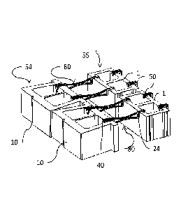
Referring to FIGS. 7 and 8, a complete bridge 80 is constructed by
inserting the connector 29 of the bridge body 20 into the connector receiver
45 of
the SWS clip 40. The bridge 80 then is positioned with the CMU clip 24 mounted
onto the top of the front side wall of a CMU 1 and the SWS clip 40 mounted
onto
the top of the back side wall 14 of an SWS unit 10, in one of the grooves 18.
If
desired, the bridge 80 could be flipped upside down and mounted to the bottoms
of the CMU and SWS units instead. Multiple complete bridges 80 are assembled
to multiple CMUs and SWS units to build a course of two walls spaced apart by
the distance provided by the complete bridges 80.
Preferably, a stand-alone CMU clip 50 is provided on the back side wall 5
of the CMU unit. The stand-alone CMU clip is similar to the SWS clip 40, but
is
sized to match the wall thickness of a CMU. Providing this stand-alone clip 50
will
ensure that when the next course of CMUs is placed on top of the present
course,
it will align vertically with the taller SWS course.
Once the course is assembled, it is filled with appropriate fill, such as
gravel or rock, which provides both mass and drainage. The fill is not shown
in
zo any of the drawings for clarity of illustration.
As shown in FIG. 9, a wall can be built by placing multiple courses of CMUs
1 and SWS units 10 on top of each prior course, connected with bridges 80 and
filled. The optional spacer 49 on top of the SWS clips 40 and stand-alone CMU
clips 50 can be used to ensure proper set-back and vertical spacing of the SWS
units and CMUs.
A single pair of walls 54, 55 formed by the SWS units and CMUs as shown
may not provide sufficient mass to support the ground behind a tall retaining
wall.
In that case, additional CMU walls 56, 57 can be provided as needed. The exact
number of walls 54, 55, 56, 57 needed will depend on the engineering
requirements for the particular ground quality and load requirements. However,
as a general matter a 15 course, 10' (3m) wall such as that shown in FIG. 9
will
require one SWS wall and three CMU walls, as shown, while a 6' (1.8m) wall
9

CA 02929964 2016-05-06
WO 2015/085282
PCT/US2014/068965
would only require one SWS wall 54 and one CMU wall 55. The extra walls 56,
57 do not need to extend all the way to the height of the SWS wall 54.
Instead,
they can be shorter, as shown, as needed to match the required load.
The additional CMU walls 56, 57 can be constructed by attaching the
stand-alone CMU clip 50 to the connector 29 on the bridge body 20, instead of
the
SWS connector 40. The assembly then is the same as for the first two walls 54,
55.
An alternative to adding walls 56, 57 is to extend the distance between
walls 54, 55, so that additional fill between the walls 54, 55 can provide
sufficient
io additional mass to meet the engineering requirements for the wall. This
can be
accomplished by providing bridge bodies 20 in a variety of lengths.
Alternatively,
a connector receiver clip 60 such as that shown in FIG. 5 can be used. The
connector receiver clip 60 has connector receivers 62 similar to the connector
receiver 45 in the SWS clip 40, formed on either side thereof. A connector 29
or
connector 33 on two bridge bodies 20 then can be inserted into the connector
receivers 60 in the connector receiver clip 60. Multiple bridge bodies 20 and
connector receiver clips 60 can be assembled serially in this fashion, if
desired
and if the materials from which they are formed have sufficient tensile
strength to
handle the load. With different size bridge bodies 20 and connector receiver
clips
zo 60, wall spacing can be provided to cover a wide range of sizes.
Another situation which may arise is a desire to position two walls very
tightly, e.g., for a non-retaining, stand-alone wall. This can be accomplished
by
using a connector clip 70 such as that shown in FIG. 6. The connector clip 70
has
a connector 72 formed on each side, which matches the connectors on the bridge
body 20. The connector 72 is essentially a very, very short bridge body, and
clips,
such as the SWS clip 40 or the stand-alone CMU clip 50, can be connected to
either side of the connector clip 70 in the same manner as to bridge body 20,
or in
combination with multiple bridge bodies 20 and clips. This will provide a very
short bridge 80 to hold two walls close together. The exact mix of clips can
be
varied to match the building units being used, for example, if SWS units 10
are
being used on both sides of the wall, then two SWS clips 40 would be used,
instead of one SWS clip 40 and one stand-alone CMU clip 50.

CA 02929964 2016-05-06
WO 2015/085282
PCT/US2014/068965
All of the bridge, clip and connector components described preferably are
formed using injection molded, fiberglass reinforced polymers, to provide
strong,
durable, corrosion resist and low cost components. However, any suitable
material may be used, such as other polymers, metals and ceramics.
Thus, a method and apparatus for constructing multi-stage walls have been
presented in the foregoing description with reference to specific embodiments,
but
many variations could be made thereto within the scope of the present
invention.
For example, the CMU clip 24 has been shown molded into the bridge body 20,
but the bridge body 20 could be formed simply with a connector 29 at both
ends,
and a stand-alone CMU clip 50 used instead of the CMU clip 24. The SWS units
10 are shown as having grooves 18 in their back side wall 14, but the entire
back
side wall 14 could be made shorter instead.
. It will be appreciated that various modifications to the referenced
embodiments may be made without departing from the scope the following claims.
11

Representative Drawing
A single figure which represents the drawing illustrating the invention.
Administrative Status

2024-08-01:As part of the Next Generation Patents (NGP) transition, the Canadian Patents Database (CPD) now contains a more detailed Event History, which replicates the Event Log of our new back-office solution.

Please note that "Inactive:" events refers to events no longer in use in our new back-office solution.

For a clearer understanding of the status of the application/patent presented on this page, the site Disclaimer , as well as the definitions for Patent , Event History , Maintenance Fee  and Payment History  should be consulted.

Event History

Description Date
Inactive: Grant downloaded 2022-08-10
Letter Sent 2022-08-09
Grant by Issuance 2022-08-09
Inactive: Cover page published 2022-08-08
Pre-grant 2022-05-26
Inactive: Final fee received 2022-05-26
Notice of Allowance is Issued 2022-05-04
Letter Sent 2022-05-04
Notice of Allowance is Issued 2022-05-04
Inactive: Approved for allowance (AFA) 2022-03-10
Inactive: Q2 passed 2022-03-10
Amendment Received - Voluntary Amendment 2022-01-27
Examiner's Interview 2022-01-24
Amendment Received - Response to Examiner's Requisition 2021-09-14
Amendment Received - Voluntary Amendment 2021-09-14
Examiner's Report 2021-08-12
Inactive: Report - No QC 2021-07-30
Change of Address or Method of Correspondence Request Received 2021-04-13
Amendment Received - Response to Examiner's Requisition 2021-04-13
Amendment Received - Voluntary Amendment 2021-04-13
Examiner's Report 2021-01-07
Inactive: Report - QC passed 2020-12-23
Common Representative Appointed 2020-11-07
Amendment Received - Voluntary Amendment 2019-12-10
Letter Sent 2019-11-20
Request for Examination Received 2019-11-05
Request for Examination Requirements Determined Compliant 2019-11-05
All Requirements for Examination Determined Compliant 2019-11-05
Common Representative Appointed 2019-10-30
Inactive: First IPC assigned 2016-05-25
Inactive: IPC assigned 2016-05-25
Inactive: Notice - National entry - No RFE 2016-05-20
Inactive: Cover page published 2016-05-19
Application Received - PCT 2016-05-17
Letter Sent 2016-05-17
Inactive: IPC assigned 2016-05-17
Inactive: First IPC assigned 2016-05-17
National Entry Requirements Determined Compliant 2016-05-06
Inactive: IPRP received 2015-12-19
Application Published (Open to Public Inspection) 2015-06-11

Abandonment History

There is no abandonment history.

Maintenance Fee

The last payment was received on 2021-11-29

Note : If the full payment has not been received on or before the date indicated, a further fee may be required which may be one of the following

  • the reinstatement fee;
  • the late payment fee; or
  • additional fee to reverse deemed expiry.

Patent fees are adjusted on the 1st of January every year. The amounts above are the current amounts if received by December 31 of the current year.
Please refer to the CIPO Patent Fees web page to see all current fee amounts.

Fee History

Fee Type Anniversary Year Due Date Paid Date
Basic national fee - standard 2016-05-06
Registration of a document 2016-05-06
MF (application, 2nd anniv.) - standard 02 2016-12-06 2016-09-19
MF (application, 3rd anniv.) - standard 03 2017-12-06 2017-11-21
MF (application, 4th anniv.) - standard 04 2018-12-06 2018-12-04
MF (application, 5th anniv.) - standard 05 2019-12-06 2019-10-04
Request for examination - standard 2019-12-06 2019-11-05
MF (application, 6th anniv.) - standard 06 2020-12-07 2020-10-07
MF (application, 7th anniv.) - standard 07 2021-12-06 2021-11-29
Final fee - standard 2022-09-06 2022-05-26
MF (patent, 8th anniv.) - standard 2022-12-06 2022-08-30
MF (patent, 9th anniv.) - standard 2023-12-06 2023-09-14
Owners on Record

Note: Records showing the ownership history in alphabetical order.

Current Owners on Record
DEAN HOLDING CORPORATION
Past Owners on Record
DANIEL J. CURRY
DANIEL SYLVESTRE
KONG CHENG MOUA
MATTHEW J. KEMPAINEN
MICHAEL STONEBURNER
PATRICK E. DEAN
Past Owners that do not appear in the "Owners on Record" listing will appear in other documentation within the application.
Documents

To view selected files, please enter reCAPTCHA code :


To view images, click a link in the Document Description column (Temporarily unavailable). To download the documents, select one or more checkboxes in the first column and then click the "Download Selected in PDF format (Zip Archive)" or the "Download Selected as Single PDF" button.

List of published and non-published patent-specific documents on the CPD .

If you have any difficulty accessing content, you can call the Client Service Centre at 1-866-997-1936 or send them an e-mail at CIPO Client Service Centre.

({010=All Documents, 020=As Filed, 030=As Open to Public Inspection, 040=At Issuance, 050=Examination, 060=Incoming Correspondence, 070=Miscellaneous, 080=Outgoing Correspondence, 090=Payment})


Document
Description 
Date
(yyyy-mm-dd) 
Number of pages   Size of Image (KB) 
Representative drawing 2022-07-14 1 8
Description 2016-05-05 11 475
Drawings 2016-05-05 3 127
Abstract 2016-05-05 1 73
Claims 2016-05-05 3 143
Representative drawing 2016-05-18 1 9
Claims 2021-04-12 14 833
Description 2021-04-12 11 541
Claims 2021-09-13 14 849
Claims 2022-01-26 14 848
Notice of National Entry 2016-05-19 1 194
Courtesy - Certificate of registration (related document(s)) 2016-05-16 1 103
Reminder of maintenance fee due 2016-08-08 1 112
Reminder - Request for Examination 2019-08-06 1 117
Courtesy - Acknowledgement of Request for Examination 2019-11-19 1 433
Commissioner's Notice - Application Found Allowable 2022-05-03 1 572
Maintenance fee payment 2023-09-13 1 26
Electronic Grant Certificate 2022-08-08 1 2,527
Maintenance fee payment 2018-12-03 1 26
National entry request 2016-05-05 9 311
Patent cooperation treaty (PCT) 2016-05-05 1 68
International search report 2016-05-05 1 57
Fees 2016-09-18 1 26
Maintenance fee payment 2017-11-20 1 26
Maintenance fee payment 2019-10-03 1 26
Request for examination 2019-11-04 2 47
International preliminary examination report 2015-12-18 6 399
Amendment / response to report 2019-12-09 3 87
Maintenance fee payment 2020-10-06 1 27
Examiner requisition 2021-01-06 5 267
Amendment / response to report 2021-04-12 48 2,612
Change to the Method of Correspondence 2021-04-12 8 395
Examiner requisition 2021-08-11 4 186
Amendment / response to report 2021-09-13 39 2,249
Maintenance fee payment 2021-11-28 1 27
Interview Record 2022-01-23 2 23
Amendment / response to report 2022-01-26 34 1,917
Final fee 2022-05-25 3 98
Maintenance fee payment 2022-08-29 1 27