Note: Descriptions are shown in the official language in which they were submitted.
CA 02930765 2016-05-13
WO 2015/075543 PCT/1B2014/002626
1
Methods and Apparatus Relating to Beverage Capsules
The present disclosure relates to methods and apparatus
relating to beverage capsules. In particular, it relates to
a capsule for the preparation of a beverage, for example
coffee, when utilised with a beverage preparation machine,
the capsule comprising a body portion and a lid which
together define an interior of the capsule for containing
beverage ingredients. Further, the disclosure relates to
methods for producing said capsules and components thereof.
Background of the disclosure
Disposable beverage capsules formed from aluminium have
been known for many years. An example is described in
EP0512470. The capsule of that document comprises a
frustroconically-shaped cup which is filled with coffee and
is closed by an aluminium cover joined to a rim which
extends from a side-wall of the cup. A capsule holder of a
brewer designed to receive the capsules comprises a flow
grill with relief surface element members. The brewer
further comprises a water injector and an annular element
with an internal recess of which the shape substantially
corresponds to the outer shape of the capsule.
In operation, the capsule of EP0512470 is placed in the
capsule holder. The water injector perforates an upper,
inlet face of the capsule. The aluminium cover of the
capsule rests on the relief surface element members of the
capsule holder. Water is injected through the water injector
and contacts the coffee. The capsule is pressurised by the
water causing the aluminium cover to be distorted outwardly
and be torn against the relief surface element members.
Extracted coffee flows through the torn aluminium cover and
CA 02930765 2016-05-13
WO 2015/075543 PCT/1B2014/002626
2
the flow grill to be discharged by the brewer into a
receptacle, for example a cup.
It is also known to provide an inlet face of the
capsule with pre-formed inlet apertures that do not require
piercing. However, this results in the disadvantage that
coffee can be lost from the capsule during handling and
transport and can lead to oxidization of the coffee during
storage. Thus, it is preferred to use closed or sealed
capsules in which the inlet apertures for feeding water into
the capsule to contact the beverage ingredient are created
by the beverage preparation machine at the time of beverage
formation. For this purpose the brewing device is typically
provided with an inlet piercer which may take the form of
one or more protruding parts, such as needles or blades,
which are moved with respect to the capsule (or vice versa)
to perforate the capsule.
More recently, it has been known to manufacture
beverage capsules of the general configuration described
above, at least in part, from a polymeric material. For
example, it is known to combine a cup-shaped body portion
formed from a material such as a PE or PP polymer, with an
aluminium-based cover to form the capsule. An example of
such is described in W02010/041179. One potential problem is
that beverage capsules made of a polymer such as PE or PP
can be difficult to perforate using the inlet piercer of
known beverage preparation machines. For example, the
material of the capsule may deflect or distort during the
piercing stage resulting in the inlet aperture not being
fully formed and the aperture therefore having a smaller
open area than desired. In another example the force applied
by the inlet piercer may be insufficient to fully form an
inlet aperture of desired size in the material of the
CA 02930765 2016-05-13
WO 2015/075543 PCT/1B2014/002626
3
capsule, in particular where the material of the capsule is
a relatively resilient polymeric material. In extreme cases,
the capsule material may deflect or distort to such an
extent, or the material of the capsule may be sufficiently
resilient, that no aperture is formed at all.
Attempts have been made to overcome this problem by
altering the geometry of the capsule to reinforce the
capsule in the region where the inlet apertures are to be
formed. W02010/041179 describes that the capsule may
comprise a sunken portion provided in the inlet wall. This
sunken portion is intended to be a reinforcing element that
cooperates with a corresponding radial ridge on the inlet
wall. W02012/080501 describes a capsule where the base (that
is the inlet wall) of the capsule is provided with a
reinforcement zone arranged circumferentially on the base as
a plurality of recesses. However, altering the geometry of
the capsule requires a complete redesign of the capsule and
can lead to the capsule becoming incompatible for use in
some beverage preparation machines. In addition, increasing
the reinforcement of the inlet wall can increase the problem
of forming inlet apertures where the force applied by the
inlet piercer is relatively low.
Summary of the Disclosure
In one aspect the present disclosure provides a method
of producing a body portion of a capsule comprising the
steps of:
forming the body portion from a polymeric
= material;
subsequently treating one or more piercing zones
of the body portion to alter one or more material
characteristics of the polymeric material of the one or more
CA 02930765 2016-05-13
WO 2015/075543
PCT/1B2014/002626
4
piercing zones relative to the material characteristics of
the polymeric material of a remainder of the body portion.
Advantageously, by altering one or more of the material
characteristics of the one or more piercing zones the body
portion can be configured as desired to allow it be pierced
sufficiently and reliably in use by a beverage preparation
machine. Since the alteration takes place after formation of
, the body portion, the technique can be applied to body
portions of any geometry and does not require a wholesale
change in the shape of the capsule intended to be formed
from the body portion.
In addition, advantageously, the material
characteristics of different zones of the body portion can
be controlled by treating one or more zones of the body
portion after moulding. This can avoid the need and
complication of trying to form a body portion from multiple
different materials. For example, the body portion may
comprise a zone intended to form a sealing interface with an
enclosing member of a beverage preparation machine in which
it will be used. It can be beneficial to use a relatively
ductile or soft material for this zone of the body portion
to allow a better seal to be formed. However, the zone or
zones of the body portion intended to be pierced can benefit
from being made relatively brittle or easier to pierce. The
present disclosure advantageously allows the material
characteristics of different portions of the body portion to
be accurately controlled.
Treating the one or more piercing zones may comprise
exposing the one or more piercing zones to radiant energy.
Advantageously, the use of radiant energy provides an
accurate means for selectively treating portions of the body
CA 02930765 2016-05-13
WO 2015/075543 PCT/1B2014/002626
portion. Portions which are not intended to be treated may
be masked so as not to be exposed to the radiant energy.
Treating the one or more piercing zones may comprise
exposing the one or more piercing zones to electromagnetic
5 radiation.
The electromagnetic radiation may be one or more of
infrared radiation, visible light radiation, ultraviolet
radiation, soft X-ray radiation, X-ray radiation, gamma-ray
radiation, and electron beam radiation.
Treating the one of more piercing zones may comprise
one or more of degrading, carbonising, foaming, ageing or
embrittling the polymeric material.
Degrading, foaming and/or carbonisation of the
polymeric material can have the advantage that the polymeric
material of the one or more piercing zones is made
structurally weaker and is hence more easily pierced by the
needles or blades of the inlet piercer. In particular,
whilst not wishing to be bound by theory, the treatment may
lead to changes in the physical material properties through
polymer chain scission processes and/or post-
crystallisation.
Aging or embrittling of the polymeric material can have
the advantage that excessive deflection or distortion of the
capsule during piercing can be limited or prevented since
the polymeric material of the one or more piercing zones is
made more brittle than before exposure. In addition, the
comparatively aged or brittle polymeric material has an
increased tendency to crack and/or fracture on failure (as
opposed to a ductile 'tearing' mode of failure that
predominates in softer polymeric materials) under the
loading of the needles or blades of the inlet piercer (which
tend to apply one or more point loads to the polymeric
CA 02930765 2016-05-13
WO 2015/075543 PCT/1B2014/002626
6
material). Fracturing and/or cracking of the polymeric
material has been found to have a tendency to form inlet
apertures that are larger in area than the area of the
impinging inlet piercer since the fractures and/or cracks in
the polymeric material have a tendency to propagate outwards
away from the location of the point loading. Consequently,
provision of the comparatively brittle material can lead to
the formation of enlarged inlet apertures with a resultant
increased flow area for the ingress of pressurised water
into the capsule.
The radiant energy may be applied to the one or more
piercing zones in the form of a focused beam.
The one of more piercing zones may be subjected to .
laser treatment.
The body portion may be moulded from the polymeric
material. The body portion may be formed as a unitary
moulding. The body portion may be moulded from a single
material. The body portion may be injection-moulded.
The body portion may be formed from a material
comprising a polyolef in. The body portion may be formed from
a material comprising a thermoplastic polyolef in. The body
portion may be formed from a material comprising
polypropylene and/or polyethylene. Alternatively, other
polymers may be used, for example polylactic acid (PLA).
The polymeric material may comprise an additive
intended to facilitate the treatment of the one or more
piercing zones by radiant energy. The additive may be one or
more compounds selected from the group of: carbon black,
graphite and doped-tin dioxide.
The tin dioxide may be doped with one or more of
antimony, fluorine, chlorine, tungsten, molybdenum, iron or
phosphorus.
CA 02930765 2016-05-13
WO 2015/075543 PCT/1B2014/002626
7
The body portion may be moulded in a cup-shape. The
body portion may comprise an inlet wall, wherein the one or
more piercing zones are located on the inlet wall.
The one or more piercing zones may comprise an annular zone.
The annular zone may be continuous in a circumferential
direction. Alternatively, the annular zone may be
discontinuous in a circumferential direction. In an example,
the annular zone may comprise a circumferential pattern,
preferably a repeating pattern.
The one or more piercing zones may comprise two or more
concentrically arranged annular zones.
The one or more piercing zones may comprise a circular
zone.
The body portion may have a thickness within the one or
more piercing zones in the range of 0.20 to 0.50mm,
preferably within the range 0.30 to 0.40mm.
The one or more piercing zones may comprise an area of
10 to 90% of an inlet wall area of the body portion.
The method may further comprise masking of the
polymeric material of a remainder of the body portion to
prevent alteration of said remainder of the body portion
during treatment.
The body portion may further comprise a sealing member
configured to form a sealing engagement with an enclosing
member of a beverage preparation machine to thereby prevent
or limit a by-pass flow of water in .use. The sealing member
may form a part of the remainder of the body portion which
is not treated. The one or more piercing zones of the body
portion may have a lower ductility than the sealing member.
The present disclosure also relates to a method of
producing a capsule for the preparation of a beverage
comprising the steps of:
CA 02930765 2016-05-13
WO 2015/075543
PCT/1B2014/002626
8
producing a body portion as described above;
inserting beverage ingredients into the body
portion; and
sealing the body portion with a lid.
The present disclosure further relates to a body
portion of a capsule obtainable by the method as described
above.
In another aspect, the present disclosure provides a
capsule for the preparation of a beverage when utilised with
a beverage preparation machine, the capsule comprising a
body portion and a lid which together define an interior of
the capsule for containing beverage ingredients;
wherein the body portion comprises one or more piercing
zones intended to be pierced in use by one or more piercers
of the beverage preparation machine to thereby provide one
or more inlet apertures for feeding water under pressure
into the interior of the capsule;
wherein the body portion is formed from a polymeric
material;
wherein the polymeric material of the one or more
piercing zones comprises a transformed structure which has
been treated after formation of the body portion to alter
one or more material characteristics of the polymeric
material of the one or more piercing zones relative to the
material characteristics of the polymeric material of a
remainder of the body portion.
The transformed structure may comprise one or more of a
degraded, carbonised, foamed, aged or embrittled structure.
The body portion may be moulded from the polymeric
material. The body portion may be a unitary moulding. The
body portion may be moulded from a single material. The body
portion may be injection-moulded.
CA 02930765 2016-05-13
WO 2015/075543
PCT/1B2014/002626
9
The body portion may be formed from a material
comprising a polyolef in. The body portion may be formed from
a material comprising a thermoplastic polyolef in. In one
example, the body portion is formed from a material
comprising polypropylene and/or polyethylene.
The polymeric material may comprise an additive
intended to facilitate the treatment of the one or more
piercing zones by radiant energy. The additive may be one or
more compounds selected from the group of: carbon black,
graphite and doped-tin dioxide. The tin dioxide may be doped
with one or more of antimony, fluorine, chlorine, tungsten,
molybdenum, iron or phosphorus.
The body portion may be cup-shaped. The body portion
may comprise an inlet wall, wherein the one or more piercing
zones are located on the inlet wall.
The one or more piercing zones may comprise an annular
zone. The annular zone may be continuous in a
circumferential direction. Alternatively, the annular zone
may be discontinuous in a circumferential direction. In an
example, the annular zone may comprise a circumferential
pattern, preferably a repeating pattern.
The one or more piercing zones may comprise two or more
concentrically arranged annular zones.
The one or more piercing zones may comprise a circular
zone.
The body portion may further comprise a sealing member
configured to form a sealing engagement with an enclosing
member of a beverage preparation machine to thereby prevent
or limit a by-pass flow of water in use.
The sealing member may form a part of the remainder of
the body portion which is not treated.
CA 02930765 2016-05-13
WO 2015/075543 PCT/1B2014/002626
The one or more piercing zones of the body portion may
have a lower ductility than the sealing member.
Brief Description of the Drawings
5 Embodiments of the present disclosure will now be
described, by way of example only, with reference to the
accompanying drawings, in which:
Figure 1 is a= schematic view of a capsule according to
10 the present disclosure;
Figure 2 is a schematic view of the capsule of Figure 1
inserted into a beverage preparation machine and prior to ,
piercing;
Figure 3 is an equivalent view to Figure 2 after
piercing of an inlet end of the capsule;
Figure 4 is a schematic end view of the capsule of
, Figure 1;
Figure 5 is a schematic representation of a first
apparatus for treating a cup-shaped body of the capsule of
Figure 1;
Figures 6a and 6b are photographs showing pierced inlet
holes in a sample capsule not subject to a treatment of the
present disclosure;
Figures 7a and 7b are photographs showing pierced inlet
holes in a sample capsule subject to an embrittlement
treatment of the present disclosure;
Figure 8 is a schematic representation of a second
apparatus for treating a cup-shaped body of the capsule of
Figure 1;
Figure 9 is a schematic representation of third
apparatus for treating a cup-shaped body of the capsule of
Figure 1; and
CA 02930765 2016-05-13
WO 2015/075543 PCT/1B2014/002626
11
Figures 10a to 10f show schematically examples of
arrangements of piercing zone(s).
=
Detailed Description
In the following description, embodiments of the
present disclosure will be described by way of example only
with reference to a representative design of capsule 1 as
shown in Figure 1. However, the present disclosure is not
limited to use with capsules of the particular design shown
in Figure 1.
The example capsule of Figure 1 comprises a cup-shaped
body portion 2 and a lid 3.
The cup-shaped body portion 2 is formed from a
polymeric material as a single, unitary injection moulding.
Examples of suitable material for forming the cup-shaped
body portion 2 include polyolef ins, including thermoplastic
polyolef ins. In one example the cup-shaped body portion 2 is
formed from a material comprising polypropylene and/or
polyethylene.
The cup-shaped body portion 2 comprises a bottom wall
5, forming an inlet end of the capsule 1, a side wall 4
extending away from the bottom wall 5 and an outwardly-
extending flange 6. A sealing element 7 may be provided on
the flange 6. In the illustrated example, the sealing
element 7 takes the form of an integral circumferential rib
protruding from the surface of the flange 6.
The lid 3, which may be formed from a suitable material
such as aluminium foil, a polymeric laminate or a
combination thereof, is adhered or otherwise sealed to the
flange 6 so as to close the cup-shaped body portion 2 to
define an interior 8 of the capsule which in use can be
CA 02930765 2016-05-13
WO 2015/075543 PCT/1B2014/002626
12
packed with a beverage ingredient such as roasted ground
coffee.
In accordance with the present disclosure, and common
to each of the embodiments described in more detail below,
the cup-shaped body portion 2 is subjected to a treatment
step, after its formation. The treatment results in
alteration of the material characteristics of at least a
portion of the cup-shaped body portion 2 compared to the
polymeric material of a remainder of the cup-shaped body
portion 2. More particularly, one or more piercing zones 30
of the cup-shaped body portion 2 are so treated.
The 'one or more piercing zones' 30 of the cup-shaped
body portion 2 encompass those one or more areas of the cup-
shaped body portion 2 which are intended, in use, to be
pierced by the beverage preparation machine in which the
capsule 1 is utilised. The location of the one or more
piercing zones 30 may vary depending on the design of the
inlet piercing arrangement of the beverage preparation
machine. For example, a schematic representation of one type
of inlet piercing arrangement is shown in Figures 2 and 3.
In these figures only a portion of the beverage preparation
machine is shown and this is shown schematically for ease of
understanding. As shown, an upper enclosing member 10 of the
beverage preparation machine is provided which has a base
wall 12 from which the inlet piercing arrangement in the
form of three piercers 13 extend. In addition, the upper
enclosing member 10 comprises a circumferential side wall 11
which terminates at an annular rim 14.
In this illustrated example, the three piercers 13 are
located in a circular arrangement around a nominal central
longitudinal axis of the upper enclosing member 10.
Consequently, in use the bottom wall 5 of the capsule 1 will
CA 02930765 2016-05-13
WO 2015/075543 PCT/1B2014/002626
13
be pierced at three points which lie in a circular
arrangement around a central longitudinal axis of the
capsule 1. Consequently, the one or more piercing zones 30
for this example may be considered to be a single annular
piercing zone 30 as shown in Figure 4. In this example, the
piercing zone 30 forms only a portion of the bottom wall 5.
This annular piercing zone 30 encompasses each of the three
locations that will be pierced in use by the piercers 13 of
the beverage preparation machine whatever the rotational
orientation of the capsule 1 about its longitudinal axis. It
can be noted that in use not all of the material of the one
or more piercing zones 30 need be pierced by the piercers
13.
Figures 10a to 10f illustrate schematically, by way of
example only, a variety of arrangements for the one or more
piercing zones 30 that may be used.
In the example of Figure 10a, as in Figure 4, the one
or more piercing zones 30 comprise a single,
circumferentially continuous annular zone.
In the example of Figure 10b the one or more piercing
zones 30 comprise two circumferentially continuous annular
zones which are arranged concentrically with respect to each
other, preferably centred on the longitudinal axis of the
cup-shaped body portion 2.
In the example of Figure 10c the one or more piercing
zones 30 comprise two circumferentially discontinuous
annular zones having a 'dashed line' appearance and which
are arranged concentrically with respect to each other,
preferably centred on the longitudinal axis of the cup-
shaped body portion 2.
In the example of Figure 10d the one or more piercing
zones 30 comprise a single annular circumferential pattern,
CA 02930765 2016-05-13
WO 2015/075543 PCT/1B2014/002626
14
preferably a repeating pattern as shown. In this example the
repeated unit is shaped as a triangle and the repeated units
directly adjoin one another such that the circumferential
pattern is continuous in the circumferential direction.
The example of Figure be is similar to that of Figure
10d except that the repeated unit is shaped as a hexagonal
shape having inverted points and the repeated units are
spaced from one another such that the circumferential
pattern is discontinuous in the circumferential direction.
In the example of Figure 10f the one or more piercing
zones 30 again comprise a circumferential pattern,
preferably a repeating pattern as shown. In this example the
repeated unit is shaped is a group of three circular areas
of decreasing size. Each repeated unit is spaced from one
another.
It will be appreciated that a great variety of
arrangements of the one or more piercing zones 30 can be
used without departing from the scope of the present
disclosure.
The bottom wall 5 of the capsule 1 may typically have a =
thickness in the range 0.20 to 0.50mm, more typically in the
range 0.30 to 0.40mm. In one example the thickness is 0.35
to 0.38mm. The thickness'of the bottom wall 5 may vary
across the extent of the bottom wall 5 or may alternatively
be uniform.
The capsule 1 is sized and configured to be received
within the upper enclosing member 10.
In use the capsule 1 is inserted into the beverage
preparation machine and the upper enclosing member 10 is
moved from a position generally of that shown in Figure 2 to
a position as shown in Figure 3 in which the upper enclosing
member 10 has been moved relative to the capsule 1 such that
CA 02930765 2016-05-13
WO 2015/075543 PCT/1B2014/002626
the annular rim 14 seals against the flange 6 of the capsule
1. (For ease of reference, the lower enclosing member and
its associated outlet piercing arrangement of the beverage
preparation machine which pierces the lid 3 has been omitted
5 from the figures). In so doing, the sealing element 7 may
contribute to the integrity of the seal so formed. As can be
seen from Figure 3, the movement of the upper enclosing
member 10 causes the piercers 13 to contact and pierce the
polymeric material of the bottom wall 5 of the capsule 1.
10 .The piercing of the bottom wall 5 allows for ingress of
water into the interior 8 to form a beverage from
interaction with beverage ingredients held in the capsule 1.
The beverage is then output via apertures formed in the lid
3 by the outlet piercing arrangement of the beverage
15 preparation machine.
The treatment step may be exposing the one or more
piercing zones 30 to radiant energy. In order to achieve
this treatment, the polymeric material of the one or more
piercing zones 30 may be exposed to a radiant energy source.
The radiant energy source emits radiant energy in a manner
such that the one or more piercing zones 30 are exposed to
the radiant energy.
A mask, either as part of the radiant energy source or
separate therefrom, may be provided to control which parts
of the material of the cup-shaped body portion 2 are exposed
to the radiant energy. For example, the mask may be a
separate element from the cup-shaped body portion 2 which is
interposed between the cup-shaped body portion 2 and the
radiant energy source or may alternatively be a layer of
suitable material which is temporarily or permanently
applied to the surface of the polymeric material of the cup-
shaped body portion 2. Any suitable material for the mask
CA 02930765 2016-05-13
WO 2015/075543 PCT/1B2014/002626
16
may be used which is opaque to the radiant energy being
utilised.
The radiant energy source maybe any only suitable
source capable of generating and emitting the required type
of radiant energy. The radiant energy source may comprise a
mechanism for generating a focussed beam of radiant energy.
Alternatively, or in addition, one or more focusing elements
may be interposed between the radiant energy source and the
cup-shaped body portion 2 to focus the radiant energy onto
the polymeric material of the one or more piercing zones 30.
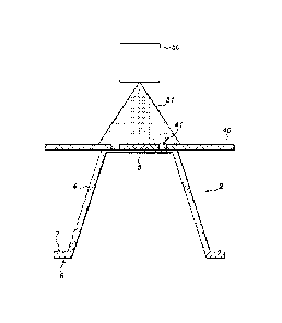
Figure 5 illustrates a first example of a treatment
apparatus wherein the polymeric material of the one or more
piercing zones 30 is subjected to a treatment involving
exposure to ultraviolet (UV) radiation 51 from a UV source
50. The treatment is carried out after moulding of the cup-
shaped body portion 2 to render the material of the one or
more piercing zones 30 comparatively brittle compared to the
polymeric material of a remainder of the cup-shaped body
portion 2.
As illustrated, a mask 40 is interposed between the UV
source 50 and the cup-shaped body portion 2. The mask 40
comprises an annular aperture 41 which allows the uv
radiation 51 to contact the polymeric material of the cup-
shaped body portion 2 in an annular zone immediately below
the annular aperture 41 but prevents exposure of a remainder
of the polymeric material of the cup-shaped body portion 2.
If desired, additives may be added to the polymer
material to speed up the embrittlement reaction.
A comparative study was undertaken of cup-shaped body
portions 2 embrittled using UV radiation. The cup-shaped
body portions 2 were injection moulded from Rigidex"
polymer, a high density polyethylene. The cup-shaped body
CA 02930765 2016-05-13
WO 2015/075543 PCT/1B2014/002626
17
portions 2 were moulded to have a bottom wall 5 of thickness
0.3mm.
A first test group of the cup-shaped body portions 2
were exposed to an ultraviolet (UV) light source, in the
form of two 9W ultraviolet lamps, emitting ultra-violet
radiation at a wavelength of 254nm. The exposure was
continued for 190 hours. A second, control group of cup-
shaped body portions 2 were not exposed to the UV light
source and were retained for the same time period of 190
hours.
At the conclusion of the exposure, piercing tests were
carried out on the bottom walls 5 of the cup-shaped body
portions 2 using a Zwick 250kN test machine at a speed of
15mm/minute. Figures 6a and 6b illustrate the typical
appearance of the bottom wall 5 of the cup-shaped body
portions 2 of the second, control group after piercing.
Figures 7a and 7b show equivalent views for the cup-shaped
body portions 2 from the first test group that were exposed
to the UV radiant energy source.
Comparison of the failure modes obtained for the
control group and the test group show a clear difference in
the nature of the failure of the polymeric material. The
pierced regions of the cup-shaped body portions 2 that were
not exposed show a smoother-boundary failure with
indications of ductility. In contrast, the cup-shaped body
portions 2 exposed to the UV radiation show crazed failure
regions with uneven boundary failure and evidence of cracks
penetrating radially outwards from the location of the
piercers.
Figures 8 and 9 illustrate second and third examples of
treatment apparatus wherein the polymeric material of the
one or more piercing zones 30 is subjected to a treatment
CA 02930765 2016-05-13
WO 2015/075543 PCT/1B2014/002626
18
involving exposure to radiation 51 from a laser source 50.
The treatment is carried out after moulding of the cup-
shaped body portion 2 to degrade, foam and/or carbonise the
material of the one or more piercing zones 30. This weakens
the material of the one or more piercing zones 30 and
renders it more easily pierceable.
The apparatus illustrated schematically in Figure 8
depicts an example of photo masking laser treatment. In
photo masking laser treatment the laser source is projected
against a mask 40 or template representing the area to be
treated. In the illustrated example the mask 40 defines an
annular treatment area. The filtered laser beam then passes
through an optical lens arrangement which concentrates the
laser beam 51 with a high energy onto the cup-shaped body
portion 2.
Typically for photo masking laser treatment the laser
is a CO2 laser with a wavelength of 10600nm. The pulse
frequency of the laser is typically higher than 100 Hz and
the laser power is typically in the range 10-200W. As the
whole area to be treated is exposed at the same time, the
treatment is very rapid.
The apparatus illustrated schematically in Figure 9
depicts an example of beam steering laser treatment. In beam
steering laser treatment the laser beam 51 is steered using
two galvanometer-operated mirrors to trace out the required
treatment area. Thus use of a mask is not essential
(although an interposed mask can be used as well if
desired).
Typically for beam steering laser treatment the laser
is a Nd:YAG (Neodymium doped Yttrium Aluminium Garnet) laser
with a wavelength of 1064nm (infrared light) or a doubled
Nd:YAG laser with a wavelength of 532nm (green light). The
CA 02930765 2016-05-13
WO 2015/075543 PCT/1B2014/002626
19
laser power is typically in the range 2.5-10W for a Nd:YAG
laser and 1-3W for a doubled Nd:YAG laser. To beneficial
produce heat generation in the polymer material it is
typical to use high pulse rate frequencies in the range 1 to
50kHz.
As noted above, with both methods of laser treatment
the goal is to produce degradation, foaming and/or
carbonisation of the material of the one or more piercing
zones 30. Degradation is the degrading of one or more of the
material characteristics of the polymer material (such as
strength, ductility, elasticity) due, in the example case,
to the localised heating of the polymer material. Foaming is
the generation of gases in the polymer due to burning or
evaporation of compounds. The hot gases produced are within
the polymer matrix so produce expanded bubbles.
Carbonisation or charring is where degradation of the
polymer material is sufficient to cause localised burning of
the polymer material.
The effects produced by the laser treatment may be
generated throughout the thickness of the material of the
one or more piercing zones 30 or may only be used to affect
a surface region of the material.
Different polymer materials have differing responses to
laser treatment. Even with the same polymer, different
grades and different colours of polymer can respond
differently to the laser radiation. Consequently, one or
more additives can be added to the polymer material to
improve is suitability for laser treatment. For example,
additives such as carbon black, graphite and doped-tin
dioxide may be added. One example is the Mark-itTm Laser
Marking Pigment produced by BASF Corporation which contains
an antimony-doped tin oxide pigment. Typically, the additive
CA 02930765 2016-05-13
WO 2015/075543 PCT/1B2014/002626
in the polymer acts as an element that readily absorbs the
laser radiation and generates heat which then affects the
surrounding polymer matrix. Thus, even polymers which might
otherwise be 'transparent' to radiation at the wavelength of
5 the laser source can be treated.
In the present description the disclosure has been
described by way of example only with reference to the
design of capsule 1 shown in the attached Figures. A number
10 of alternatives will be understood to be within the scope of
the disclosure as set out in the appended claims.
For example, the body portion 2 of the capsule may be
other than cup-shaped.
For example, it has been described that the cup-shaped
15 body portion 2 may comprise a sealing element 7 in the form
of a circumferential rib protruding from the surface of the
flange 6. However, other forms of sealing element may also
be provided either on the flange 6 or on other portions of
the cup-shaped body portion 2, such as the bottom wall 5 or
20 side wall 4. For example the sealing element 7 may take the
form of a plurality of ridges, a step formation, an inclined
surface or similar geometric form which achieves the
necessary sealing interface with the upper enclosing member
of the beverage preparation machine.
For example, while the description has described the
cup-shaped body portion 2 being formed from a single unitary
moulding, the cup-shaped body portion 2 may be formed from
more than one piece and may be formed by methods other than
injection moulding. In addition, the cup-shaped body portion
2 may be formed from two or more different materials. For
example, it may be formed as a co-moulding of two different
polymeric materials.
CA 02930765 2016-05-13
WO 2015/075543 PCT/1B2014/002626
21
For example, in the attached Figures the capsule has
been shown in schematic form and in particular, the cup-
shaped body portion 2 has been shown in a simplified manner
showing simply the bottom wall 5, side wall 4 and an
outwardly extending flange 6. However, other features may be
present as part of the cup-shaped body portion 2 as well
known in the art. For example one or more reinforcing
structures may be provided, for example ridges or ribs for
strengthening the structure of the cup-shaped body portion
2. The capsule 1 may also be provided with an internal
filter at or near the inlet end of the bottom wall 5 and/or
the outlet end of the lid 3.
For example, in the above description, the beverage '
preparation machine is provided with three piercers 13 which
pierce the bottom wall 5 along an annular or circular path
around the longitudinal axis of the capsule 1. The reader
will understand that a wide range of other piercing
arrangements can be contemplated. Consequently, an equally
wide range of shapes, sizes and locations of the one or more
piercing zones 30 can be contemplated. For example, the one
or more piercing zones 30 may comprise one or more circular
areas as opposed to annular areas; the one or more piercing
zones 30 may extend to cover the whole of the bottom wall 5;
the one or more piercing zones 30 may not be rotationally
symmetric about the longitudinal axis of the capsule 1 - in
particular where the shape or design of the capsule 1
prevents its rotation within the upper enclosing member of
the beverage preparation machine.
For example, in the above description, the capsule 1
has been described having a lid 3 which in use is torn or
pierced by a lower enclosing member of the beverage
preparation machine. However, the capsule 1 may take other
CA 02930765 2016-05-13
WO 2015/075543 PCT/1B2014/002626
22
forms, for example wherein the outlet of the capsule is
formed as a pre-pierced or porous sheet or wall which is not
intended to be pierced or torn by the lower enclosing member
of the beverage preparation machine in use.
=