Note: Descriptions are shown in the official language in which they were submitted.
CA 02931141 2016-05-19
WO 2015/082650 PCT/EP2014/076648
HEATED AEROSOL GENERATING ARTICLE WITH AIR-FLOW BARRIER
The present specification relates to heated aerosol-generating articles for
use with an
aerosol-generating device comprising a heating element, the articles having a
lowered propensity
for ignition, for example when brought into contact with a flame.
Aerosol-generating articles in which an aerosol-forming substrate, such as a
tobacco
containing substrate, is heated rather than combusted are known in the art.
The aim of such
heated aerosol-generating articles is to reduce known harmful smoke
constituents produced by the
combustion and pyrolytic degradation of tobacco in conventional cigarettes.
A conventional cigarette is lit when a user applies a flame to one end of the
cigarette and
draws air through the other end. The localised heat provided by the flame and
the oxygen in the air
drawn through the cigarette cause the end of the cigarette to ignite, and the
resulting combustion
generates an inhalable smoke. By contrast in heated aerosol-generating
articles, an inhalable
aerosol is typically generated by the transfer of heat from a heat source to a
physically separate
aerosol-forming substrate or material, which may be located within, around or
downstream of the
heat source. During consumption, volatile compounds are released from the
aerosol-forming
substrate by heat transfer from the heat source and entrained in air drawn
through the aerosol-
generating article. As the released compounds cool, they condense to form an
aerosol that is
inhaled by the consumer.
Heated aerosol-generating articles comprising tobacco for generation of an
aerosol by
heating rather than burning are known in the art. For example, W02013/102614
discloses an
aerosol-generating system comprising a heated aerosol-generating article and
an aerosol-
generating device having a heater for heating the heated aerosol-generating
article to produce an
aerosol.
Tobacco used as part of an aerosol-forming substrate in heated aerosol-
generating articles
is designed to prnritire an aprncnI when heated rather than when humeri Thus,
such tobacco
typically contains high levels of aerosol formers, such as glycerine or
propylene glycol. If a user
were to light a heated aerosol-generating article and smoke it as if it were a
conventional cigarette
that user would not receive the intended user experience. It would be
desirable to produce a
heated aerosol-generating article that has a lowered propensity for flame
ignition. Such a heated
aerosol-generating article would be preferably difficult to light during
attempts to light the article
with a lighter, such as a flame, in the manner of traditional cigarettes.
A heated aerosol-generating article may be provided for use with an aerosol-
generating
device having a heating element. The heated aerosol-generating article
comprises an aerosol-
forming substrate and a breachable air-flow barrier assembled within a wrapper
to form a rod. The
rod has a mouth end and a distal end upstream from the mouth end, and the
breachable air-flow
barrier is positioned to substantially prevent air being drawn through the
aerosol-forming substrate
CA 02931141 2016-05-19
WO 2015/082650 PCT/EP2014/076648
2
when a user draws on the mouth end of the rod. The aerosol-forming substrate
comprises a
gathered sheet of aerosol-forming material.
If a heat source, such as a flame or other cigarette lighter, is applied to
the distal end of the
heated aerosol-generating article and a user draws on the mouth end while the
breachable air-flow
barrier is intact, air will not be able to flow through the aerosol-forming
substrate. Although the
aerosol-forming substrate would be heated, the lack of air flow means that the
propensity for
ignition and combustion of the aerosol-forming substrate is reduced. Thus, the
breachable air-flow
barrier helps mitigate against the risk of a user igniting the aerosol-forming
substrate by applying a
flame, or other ignition source, to the aerosol-generating article. The risk
of the article being ignited
inadvertently or unintendedly is reduced.
The reduced propensity for ignition is the result of an increased effective
resistance to draw
(RTD) through the aerosol-forming substrate while the breachable air-flow
barrier is intact. The
entire heated aerosol-generating article may have a high RTD. Preferably the
heated aerosol-
generating article has RTD in excess of 1000 mm H20 when the air-flow barrier
is intact, but
between 30 and 100 mm H20 when the air-flow barrier is breached.
Preferably, the aerosol-generating article is a smoking article that generates
an aerosol that
is directly inhalable into a user's lungs through the user's mouth. More
preferably, the aerosol-
generating article is a smoking article that generates a nicotine-containing
aerosol that is directly
inhalable into a user's lungs through the user's mouth.
As used herein, the term 'aerosol-generating device' is used to describe a
device that
interacts with an aerosol-forming substrate of an aerosol-generating article
to generate an aerosol.
Preferably, the aerosol-generating device is a smoking device that interacts
with an aerosol-
forming substrate of an aerosol-generating article to generate an aerosol that
is directly inhalable
into a user's lungs thorough the user's mouth. The aerosol-generating device
may be a holder for
a smoking article.
For the avoidance of doubt, the term 'heating element' is used to mean one or
more heating
elements.
The breachable air-flow barrier may be disposed upstream of the aerosol-
forming
substrate. Alternatively, the breachable air-flow barrier may be disposed
upstream of the mouth
end but downstream of the aerosol forming substrate.
The breachable air-flow barrier may comprise a rupturable element spanning a
cross-
section of the rod to substantially prevent air-flow along the rod. In
particular, air flow through the
aerosol-forming substrate is substantially prevented. The rupturable element
may be configured to
be ruptured by physical interaction with a portion of an aerosol-generating
device. The rupturable
element may comprise a rupturable septum formed from a material such as foil,
paper, polymer or
ceramic. Such a rupturable septum may be designed to rupture when interacting
with a rupturing
member, such as a spike or projection, of an aerosol-generating device.
CA 02931141 2016-05-19
WO 2015/082650 PCT/EP2014/076648
3
The breachable air-flow barrier may comprise a fusible septum disposed within
the rod. For
example, the fusible septum may be arranged to melt when heated by a heating
element of an
aerosol-generating device. The fusible septum may be a disc or plug of low
melting point material,
for example a wax such as paraffin wax.
The heated aerosol-generating article may comprise a plurality of elements,
including the
aerosol-forming substrate and the breachable air-flow barrier, assembled
within a wrapper, such as
a cigarette paper.
The heated aerosol-generating article is preferably for use with an aerosol-
generating
device that comprises an insertable heating element for insertion into a
distal end of the heated
aerosol-generating article. The heating element may be brought into contact
with the aerosol-
forming substrate within the aerosol-generating article by removing the
breachable air-flow barrier
or by rupturing the breachable air-flow barrier. Prior to use, the breachable
air-flow barrier provides
some mitigation against ignition of the aerosol-forming substrate using an
external ignition source
such as a flame.
The aerosol-forming substrate may be in the form of a rod comprising, or
consisting of, a
gathered sheet of aerosol-forming material circumscribed by a wrapper. The
gathered sheet of
aerosol-forming material may be a sheet of tobacco such as a sheet of
homogenised tobacco. The
aerosol-forming substrate is a solid aerosol-forming substrate. The aerosol-
forming substrate does
not comprise a reservoir of liquid.
The gathered sheet of material preferably extends along substantially the
entire rod length
of the rod and across substantially the entire transverse cross-sectional area
of the rod.
Preferably, rods according to the specification are of substantially uniform
cross-section.
Rods according to various aspects of the specification may be produced having
different
dimensions depending upon their intended use. The heated aerosol-generating
article is in the
form of a rod and the aerosol-forming substrate, which is a component part of
the heated aerosol-
generating article, may also be in the form of a rod.
Rods according to the specification may have a diameter of between about 5 mm
and
about 10 mm depending upon their intended use.
For example, rods according to the specification may have a rod length of
between about 5
mm and about 150 mm depending upon their intended use.
In preferred embodiments, rods according to the specification for use as
aerosol-forming
substrates in heated aerosol-generating articles may have a rod length of
between about 5 mm
and about 20 mm or about 30 mm.
Rods according to the specification of a desired unit rod length may be
produced by
forming a rod of multiple unit rod length and then cutting or otherwise
dividing the rod of multiple
unit rod length into multiple rods of the desired unit rod length.
For example, rods having a rod length of about 15 mm for use as aerosol-
forming
CA 02931141 2016-05-19
WO 2015/082650 PCT/EP2014/076648
4
substrates in heated aerosol-generating articles may be produced by forming a
rod having a rod
length of about 150 mm and then severing the elongate rod into ten rods having
a rod length of
about 15 mm.
As used herein, the term 'rod' is used to denote a generally cylindrical
element of
substantially circular, oval or elliptical cross-section.
As used herein, the term 'sheet' denotes a laminar element having a width and
length
substantially greater than the thickness thereof. The width of a sheet is
greater than 10 mm,
preferably greater than 20 mm or 30 mm.
As used herein, the term "co-laminated sheet" denotes a single sheet formed
from two or
more layers of material in intimate contact with one another.
As used herein, the term "aerosol-forming material" denotes a material that is
capable of
releasing volatile compounds upon heating to generate an aerosol. An aerosol-
forming substrate
may comprise or consist of an aerosol-forming material.
As used herein, the term 'rod length' denotes the dimension in the direction
of the
cylindrical axis of rods as described herein.
As used herein, the term 'homogenised tobacco material' denotes a material
formed by
agglomerating particulate tobacco.
As used herein, the term 'gathered' denotes that the sheet of tobacco material
is
convoluted, folded, or otherwise compressed or constricted substantially
transversely to the
cylindrical axis of the rod.
As used herein, the terms 'upstream' and 'downstream' are used to describe the
relative
positions of components, or portions of components, of aerosol-generating
articles comprising rods
as described herein in relation to the direction of air drawn through the
aerosol-generating articles
during use thereof.
The gathered sheet of aerosol-forming material may be a textured sheet of
material. Use of
a textured sheet of m,aterial mIay advantageoilsly facilitate gathering of the
sheet to form an
aerosol-forming substrate as described herein.
As used herein, the term 'textured sheet' denotes a sheet that has been
crimped,
embossed, debossed, perforated or otherwise deformed. Textured sheets of
material may
comprise a plurality of spaced-apart indentations, protrusions, perforations
or a combination
thereof.
As used herein, the term 'crimped sheet' is intended to be synonymous with the
term
'creped sheet' and denotes a sheet having a plurality of substantially
parallel ridges or
corrugations.
A number of aerosol-generating articles in which an aerosol-forming substrate
is heated
rather than combusted have been proposed in the art. Typically in heated
aerosol-generating
articles, an aerosol is generated by the transfer of heat from a heat source,
for example a
CA 02931141 2016-05-19
WO 2015/082650 PCT/EP2014/076648
chemical, electrical or combustible heat source, to a physically separate
aerosol-forming substrate,
which may be located within, around or downstream of the heat source.
As used herein, the term 'aerosol-forming substrate' denotes a substrate
consisting of or
comprising an aerosol-forming material that is capable of releasing volatile
compounds upon
5 heating to generate an aerosol.
Rods used as aerosol-forming substrates in heated aerosol-generating articles
are typically
significantly shorter in rod length than rods of combustible smokable material
in conventional lit-
end smoking articles.
In preferred embodiments, the heated aerosol-generating articles described
herein are for
use in electrically-operated aerosol-generating systems in which the aerosol-
generating substrate
of the heated aerosol-generating article is heated by an electrical heat
source. Such heated
aerosol-generating articles are frequently constructed having an aerosol-
forming substrate at a
distal end. Thus, a user may inadvertently attempt to light the article in a
traditional manner. The
reduced ignition propensity of heated aerosol-generating articles comprising a
breachable air-flow
barrier may advantageously dissuade a user from attempting to ignite the
article.
Heated aerosol-generating articles may be of the type disclosed in EP-A-0 822
670.
Preferred embodiments of aerosol-generating articles comprise gathered sheets
of
homogenised tobacco material as the aerosol-forming substrate. In certain
embodiments, sheets of
homogenised tobacco material may have a tobacco content of at least about 40%
by weight on a
dry weight basis or of at least about 50% by weight on a dry weight basis. In
other embodiments,
sheets of homogenised tobacco material may have a tobacco content of about 70%
or more by
weight on a dry weight basis. The use of sheets of homogenised tobacco
material having high
tobacco content advantageously generates aerosols with enhanced tobacco
flavour.
Sheets of homogenised tobacco material may comprise one or more intrinsic
binders, that
is tobacco endogenous binders, one or more extrinsic binders, that is tobacco
exogenous binders,
or a combination thereof to help agglomerate the particulate tobacco.
P,Iternatively, or in addition,
sheets of homogenised tobacco material may comprise other additives including,
but not limited to,
tobacco and non-tobacco fibres, aerosol-formers, humectants, plasticisers,
flavourants, fillers,
aqueous and non-aqueous solvents and combinations thereof.
Suitable extrinsic binders for inclusion in sheets of homogenised tobacco
material are
known in the art and include, but are not limited to: gums such as, for
example, guar gum, xanthan
gum, arabic gum and locust bean gum; cellulosic binders such as, for example,
hydroxypropyl
cellulose, carboxymethyl cellulose, hydroxyethyl cellulose, methyl cellulose
and ethyl cellulose;
polysaccharides such as, for example, starches, organic acids, such as alginic
acid, conjugate
base salts of organic acids, such as sodium-alginate, agar and pectins; and
combinations thereof.
Homogenised tobacco material may comprise between about 1% and about 5% non-
tobacco fibres by weight on a dry weight basis.
CA 02931141 2016-05-19
WO 2015/082650 PCT/EP2014/076648
6
Suitable aerosol-formers and humectants for inclusion in sheets of homogenised
tobacco
material are known in the art and include, but are not limited to: polyhydric
alcohols, such as
triethylene glycol, 1,3-butanediol and glycerine; esters of polyhydric
alcohols, such as glycerol
mono-, di- or triacetate; and aliphatic esters of mono-, di- or polycarboxylic
acids, such as dimethyl
dodecanedioate and dimethyl tetradecanedioate.
For example, sheets of homogenised tobacco material may have an aerosol former
content
of between about 5% and about 30% by weight on a dry weight basis. Heated
aerosol-generating
articles may preferably include homogenised tobacco having an aerosol former
content of greater
than 5% to about 30%. The aerosol former may preferably be glycerine.
Sheets of homogenised tobacco material for use in forming heated aerosol-
generating
articles as described herein are preferably formed by a casting process of the
type generally
comprising casting a slurry comprising particulate tobacco and one or more
binders onto a
conveyor belt or other support surface, drying the cast slurry to form a sheet
of homogenised
tobacco material and removing the sheet of homogenised tobacco material from
the support
surface.
For example, in certain embodiments sheets of homogenised tobacco material may
be
formed from slurry comprising particulate tobacco, guar gum, cellulose fibres
and glycerine by a
casting process.
Sheets of homogenised tobacco material may be textured using suitable known
machinery
for texturing filter tow, paper and other materials.
For example, sheets of homogenised tobacco material may be crimped using a
crimping
unit of the type described in CH-A-691156, which comprises a pair of rotatable
crimping rollers.
However, it will be appreciated that sheets of homogenised tobacco material
may be textured
using other suitable machinery and processes that deform or perforate the
sheets of homogenised
tobacco material.
Prerafairably, chcicite nf fnhannn matorial fnr i leo in forming
atarnenl_fnrming el theft-ate:lc nf
heated aerosol-generating articles have a width of at least about 25 mm. In
certain embodiments
sheets of material may have a width of between about 25 mm and about 300 mm.
Preferably, the
sheets of material have a thickness of at least about 50 pm to about 300 pm.
In certain embodiments, individual sheets of material may have a thickness of
between 10
pm and about 250 pm. In certain embodiments, sheets of homogenised tobacco
material may
have a grammage 100 g/m2 and about 300 g/m2.
A method may be provided of forming an aerosol-forming substrate for a heated
aerosol-
generating article. The method may comprise the steps of: providing a
continuous sheet
comprising an aerosol-forming material; gathering the sheet transversely
relative to the longitudinal
axes thereof; circumscribing the gathered sheet with a wrapper to form a
continuous rod, and
severing the continuous rod into a plurality of discrete rods of aerosol-
forming substrate. The
CA 02931141 2016-05-19
WO 2015/082650 PCT/EP2014/076648
7
aerosol-forming material may be any aerosol-forming material described above,
and is preferably
homogenised tobacco. In certain embodiments the wrapper is any suitable
material such as a
cigarette paper.
The method may further comprise texturing the continuous sheet. For example,
the method
may comprise crimping, embossing, perforating or otherwise texturing the
continuous sheet prior to
gathering.
A system may be provided comprising a heated aerosol-generating device and an
aerosol-
generating article for use with the device. The aerosol-generating article may
be any heated
aerosol-generating article as described herein. For example, a system may
comprise a heated
aerosol-generating article comprising an aerosol-forming substrate and a
breachable air-flow
barrier assembled within a wrapper to form a rod having a mouth end and a
distal end upstream
from the mouth end, in which the breachable air-flow barrier is positioned to
substantially prevent
air being drawn through the aerosol-forming substrate when a user draws on the
mouth end of the
rod. The system may further comprise an aerosol-generating device having a
heating element, the
aerosol-generating device comprising means for breaching the breachable air-
flow barrier of the
aerosol-generating article to allow air to be drawn through the aerosol-
forming substrate when a
user draws on the mouth end of the rod.
The aerosol-generating device may comprise a breaching element arranged to be
inserted
into the distal end of the heated aerosol-generating article when the heated
aerosol-generating
article is engaged with the aerosol-generating device to breach the breachable
air-flow barrier. The
breaching element may be a heating element for heating the aerosol-forming
substrate.
Alternatively, the breaching element may be a projection that does not
function as a heating
element.
A method of smoking a heated aerosol-generating article comprising an aerosol-
forming
substrate and a breachable air-flow barrier assembled within a wrapper to form
a rod having a
mouth end and a distal end upstream from the mouth end may be provided. The
method
comprises the steps of; a) coupling the distal end of the rod with an aerosol-
generating device
having a heating element, b) breaching the breachable air-flow barrier, c)
actuating the heating
element to heat the aerosol-forming substrate and generate an aerosol, and d)
inhaling the aerosol
through the mouth end of he rod. Steps a), b) and c) may be carried out in any
order.
The step of coupling the distal end of the rod with the aerosol-generating
device may cause
a breaching element to penetrate the distal end of the aerosol-generating
article thereby breaching
the breachable air-flow barrier.
The step of actuating the heating element to heat the aerosol-forming
substrate may cause
a fusible septum to melt thereby breaching the breachable air-flow barrier.
Specific embodiments will be further described, by way of example only, with
reference to
the accompanying drawings in which:
CA 02931141 2016-05-19
WO 2015/082650 PCT/EP2014/076648
8
Figure 1 illustrates an embodiment of an aerosol-generating article as
described herein;
Figure 2 illustrates an alternative embodiment of an aerosol-generating
article as described
herein
Figure 3 illustrates an aerosol-generating system comprising an electrically-
operated
aerosol-generating device and an aerosol-generating article as illustrated in
Figure 1; and
Figure 4 is a schematic cross-sectional diagram of the aerosol-generating
device illustrated
in Figure 3.
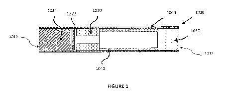
Figure 1 illustrates an embodiment of a heated aerosol-generating article 1000
comprising
a rod as described herein. The article 1000 comprises five elements; an
aerosol-forming substrate
1020, a breachable air-flow barrier 1222, a hollow cellulose acetate tube
1030, a spacer element
1040, and a mouthpiece filter 1050. These five elements are arranged
sequentially and in coaxial
alignment and are assembled by a cigarette paper 1060 to form the aerosol-
generating article
1000. The article 1000 has a mouth-end 1012, which a user inserts into his or
her mouth during
use, and a distal end 1013 located at the opposite end of the article to the
mouth end 1012. The
embodiment of an aerosol-generating article illustrated in Figure 1 is
particularly suitable for use
with an electrically-operated aerosol-generating device comprising a heater
for heating the aerosol-
forming substrate. The article could also be used with other types of aerosol-
generating devices,
for example aerosol-generating articles with gas-powered heaters.
When assembled, the article 1000 is about 45 millimetres in length and has an
outer
diameter of about 7.2 millimetres and an inner diameter of about 6.9
millimetres.
The aerosol-forming substrate 1020 comprises a rod formed from a crimped and
gathered
sheet of homogenised tobacco wrapped in filter paper to form a plug. The
breachable airflow
barrier is a frangible paper disc located downstream of the aerosol-forming
substrate and upstream
of the hollow cellulose acetate tube 1030. A user may inadvertently attempt to
ignite the aerosol-
forming substrate 1020 by applying a flame to the distal end 1013 and
simultaneously drawing air
through the mouthpiece. Should this occur, the frangible paper disc will
prevent air-flow through the
heated aerosol-generating article, thereby restricting the oxygen available in
the region of the
aerosol-forming substrate for ignition and combustion. This lowered propensity
for ignition and
combustion may be sufficient for the user to desist in attempts to ignite the
article.
An aerosol-generating article 1000 as illustrated in Figure 2 is designed to
engage with an
aerosol-generating device in order to be consumed. Such an aerosol-generating
device includes
means for heating the aerosol-forming substrate 1020 to a sufficient
temperature to form an
aerosol. Typically, the aerosol-generating device may comprise a heating
element that surrounds
the aerosol-generating article 1000 adjacent to the aerosol-forming substrate
1020, or a heating
element that is inserted into the aerosol-forming substrate 1020. The
breachable airflow barrier
could alternatively be a ceramic disc or a foil disc.
Figure 2 illustrates an alternative embodiment of a heated aerosol-generating
article 3000
CA 02931141 2016-05-19
WO 2015/082650 PCT/EP2014/076648
9
comprising a rod as described herein. The article 3000 comprises five
elements; an aerosol-
forming substrate 3020, a breachable air-flow barrier 3222, a hollow cellulose
acetate tube 3030,
an aerosol-cooling element 3040, and a mouthpiece filter 3050. The aerosol-
cooling element 3040
acts as a spacer element as described in relation to Figure 1 as well as an
aerosol-cooling
element. In use, volatile substances released from the aerosol-forming
substrate 3020 pass along
the aerosol-cooling element 3040 towards a mouth end 3012 of the aerosol-
generating article
3000. The volatile substances may cool within the aerosol-cooling element 3040
to form an
aerosol that is inhaled by the user. In the embodiment illustrated in Figure
2, the aerosol-cooling
element comprises a crimped and gathered sheet of polylactic acid
circumscribed by a wrapper.
These five elements are arranged sequentially and in coaxial alignment and are
assembled by a
cigarette paper 3060 to form the aerosol-generating article 3000. The article
3000 has a mouth-
end 3012, which a user inserts into his or her mouth during use, and a distal
end 3013 located at
the opposite end of the article to the mouth end 3012.
Figure 3 illustrates a portion of an electrically-operated aerosol-generating
system 2000
that utilises a heating blade 2100 to heat an aerosol-generating substrate
1020 of an aerosol-
generating article 1000, 3000. The heating blade is mounted within an aerosol
article receiving
chamber of an electrically-operated aerosol-generating device 2010. The
aerosol-generating
device defines a plurality of air holes 2050 for allowing air to flow to the
aerosol-generating article
1000. On engagement with the aerosol-generating device 2010 frangible paper
disc 1222 is
ruptured by the heating blade 2100, which passes through the aerosol¨forming
substrate. Thus,
when the heating blade is actuated and a user draws on the mouth end of the
aerosol-generating
article, air is able to flow into the article and deliver an aerosol to the
user through the mouth end.
Air flow is indicated by arrows on Figure 3.
The aerosol-generating device comprises a power supply and electronics, which
are
illustrated in Figure 4. The aerosol-generating article 1000 of Figure 4 is as
described in relation to
Figure 1. 'Once engaged vvith an aerosol-generating davice, a user dravvs on
11. he mouth-end 41 0 41 2
of the smoking article 1000 and the aerosol-forming substrate 1020 is heated
to a temperature of
about 375 degrees Celsius. At this temperature, volatile compounds are evolved
from the sheet of
cast-leaf tobacco of the aerosol-forming substrate 1020. These compounds
condense to form an
aerosol. The aerosol is drawn through the filter 1050 and into the user's
mouth.
In Figure 4, the components of the aerosol-generating device 2010 are shown in
a
simplified manner. Particularly, the components of the aerosol-generating
device 2010 are not
drawn to scale in Figure 4. Components that are not relevant for the
understanding of the
embodiment have been omitted to simplify Figure 4.
As shown in Figure 4, the aerosol-generating device 2010 comprises a housing
6130. The
heating element 6120 is mounted within an aerosol-generating article receiving
chamber within the
housing 6130. The aerosol-generating article 1000 (shown by dashed lines in
Figure 4) is inserted
CA 02931141 2016-05-19
WO 2015/082650 PCT/EP2014/076648
into the aerosol-generating article receiving chamber within the housing 6130
of the aerosol-
generating device 2010 such that the heating element 6120 is directly inserted
into the aerosol-
forming substrate 1020 of the aerosol-generating article 1000.
Within the housing 6130 there is an electrical energy supply 6140, for example
a
5 rechargeable lithium ion battery. A controller 6150 is connected to the
heating element 6120, the
electrical energy supply 6140, and a user interface 6160, for example a button
or display. The
controller 6150 controls the power supplied to the heating element 6120 in
order to regulate its
temperature.
The exemplary embodiments described above are not limiting. In view of the
above-
10 discussed exemplary embodiments, other embodiments consistent with the
above exemplary
embodiment will now be apparent to one of ordinary skill in the art.