Note: Descriptions are shown in the official language in which they were submitted.
CA 02931292 2016-05-20
WO 2015/074143
PCT/CA2014/051066
- 1 -
CONTROL SYSTEM FOR A FLEXIBLE FUEL INTERNAL
COMBUSTION ENGINE
Field of the Invention
[0001] The
present application relates to a control system for a flexible fuel
internal combustion engine, and more specifically to a technique of
controlling fuel
injection in an internal combustion engine that is configured to operate using
multiple
fuels.
Back2round of the Invention
[0002] Flexible
fuel internal combustion engines are fuelled with one or more
fuels. These engines can operate in a dual fuel mode where the engine is
simultaneously fuelled with two different fuels. Alternatively or
additionally, these
engines can operate in a bi-fuel mode where the engine is configured to fuel
with the
two different fuels but only operates with one of these fuels at a time.
[0003]
Conventional engines fuelled with liquid fuels (gasoline, diesel, ethanol
etc.) include control systems (OEM control systems) in engine control units
(ECU)
that monitor and control engine operation and the introduction of the liquid
fuels.
Sensors monitoring various engine parameters provide signals to these OEM
control
systems that are input into algorithms that control engine performance. The
algorithms output signals to control various actuators and fuel injectors to
maintain
certain engine parameters within predetermined thresholds. The OEM control
systems
have evolved over several decades and comprise advanced control techniques.
These
engines are being adapted to be additionally or alternatively fuelled with
gaseous fuels
(natural gas, liquefied natural gas, liquid propane gas, etc.), operating in
the dual-fuel
and/or bi-fuel modes.
[0004] Gaseous fuel control systems govern the delivery of gaseous fuel to
fuel
injectors and command these fuel injectors to introduce a predetermined
quantity of
gaseous fuel at a specific timing into intake air systems and/or combustion
chambers.
CA 02931292 2016-05-20
WO 2015/074143
PCT/CA2014/051066
-2-
Sensors monitoring various parameters of a gaseous fuel supply system provide
signals to the gaseous fuel control system representative of these parameters,
and
together with other engine parameters are input into algorithms that control
engine
performance and output signals to control various actuators and fuel injectors
to
maintain certain engine parameters within predetermined thresholds. The
gaseous fuel
control system comprises advanced techniques for controlling the combustion of
gaseous fuel such that the demanded power and speed are met and emissions are
maintained below predetermined thresholds.
[0005] United
States Patent No. US 8,498,799, issued July 30, 2013 to Matthews
et al., the '799 patent, discloses a technique for controlling fuel injection
in engines
configured to operate using different fuels. An engine control module (ECM)
controls
the engine and also calculates a first fuel mass of a first fuel and a second
fuel mass of
a second fuel. The first fuel mass is introduced by a first fuel injection
system that is
commanded by the engine control module. The second fuel mass is introduced by
a
second fuel injection system that is commanded by a second control module. The
second control module commands fuel injectors and other components in the
second
fuel injection system. Although the second control module can determine pulse
widths
used to actuate the fuel injectors based on the second fuel mass received from
the first
control module, the second control module does not comprise any algorithms for
determining the quantity of the second fuel to be introduced or the timing at
which the
second fuel is introduced by the second fuel injection system.
[0006] United
States Patent Publication No. US 2013/0103286, published on
April 25, 2013 by Guido et al., the '286 patent publication, discloses a
technique of
supplying fuel to an engine via multiple fuel paths. A controller receives
signals from
various sensors coupled to the engine, representative of conventional engine
parameters, and commands second fuel injectors. A secondary controller
receives
pulse width information from the controller over a communication bus that it
uses to
actuate first fuel injectors. The first and second fuel injectors may be
supplied with
the same type of fuel, or different types of fuel. The secondary controller
receives
signals from temperature and pressure sensors employed to monitor a fuel that
is
CA 02931292 2016-05-20
WO 2015/074143
PCT/CA2014/051066
-3-
introduced by the first fuel injectors, and can provide a signal to a fuel
gauge. The
controller broadcasts injector pulse widths, start of injector opening timing
and/or stop
of injector opening timing to the secondary controller that employs this
information to
actuate the first fuel injectors.
[0007] The second control module of '799 and the secondary controller of '286
can actuate gaseous fuel injectors in a multi-fuel engine. However, neither of
these
controllers comprises a gaseous fuel control system that determines the
quantity of
gaseous fuel and timing at which that quantity is introduced by gaseous fuel
injectors.
[0008] A
flexible fuel control system for a conventional liquid fuel and an
alternative gaseous fuel comprises an OEM control system and a gaseous fuel
control
system. Each engine manufacturer has its own OEM control system designed for
conventional liquid fuel operation that comprises different and/or proprietary
algorithms that must interface and interoperate with a gaseous fuel control
system in a
flexible fuel control system. There is a need for a flexible fuel control
system that
reduces the changes required in each OEM control system in order to operate
with a
gaseous fuel control system.
Summary of the Invention
[0009] An improved control system for an engine comprises a first control unit
programmed to generate a first pulse width to actuate a first fuel injector to
introduce
a first fuel; a second control unit programmed to generate a second pulse
width to
actuate a second fuel injector to introduce a second fuel; and a communication
line
between the first and second control units. The first control unit determines
a total
fuel energy amount to be introduced by the first and second fuel injectors.
The second
control unit determines a first fraction of the total fuel energy amount to be
from the
first fuel and a second fraction of the total fuel energy amount to be from
the second
fuel. The first fuel can be a liquid fuel and the second fuel can be a gaseous
fuel. The
first fuel can be one of gasoline, diesel, ethanol and mixtures of these
fuels. The
second fuel can be at least one butane, ethane, hydrogen, methane, propane and
natural gas and mixtures of these fuels. The first and second fuel injectors
can be
CA 02931292 2016-05-20
WO 2015/074143
PCT/CA2014/051066
-4-
direct fuel injectors, or injectors that introduce fuel into an intake
manifold. The
communication line can be a dedicated link between the first control unit and
the
second control unit. In a preferred embodiment the communication line is a
controller
area network bus. The second control unit can be programmed to transfer
injection
timing information to the first control unit over the communication line.
[0010] In a preferred embodiment, the first control unit is further programmed
to
determine the first pulse width as a function of the first fraction of the
total fuel
energy amount, and the second control unit is further programmed to determine
the
second pulse width as a function of the second fraction of the total fuel
energy
amount.
10011] In another preferred embodiment, the first control unit transfers
the total
fuel energy amount to the second control unit over the communication line. The
total
energy amount is one of a first quantity of the first fuel and a second
quantity of the
second fuel. The second control unit transfers at least one of the first
fraction and the
second fraction to the first control unit over the communication line. The
first control
unit can be further programmed to calculate a third quantity of the first fuel
to be
injected by the first fuel injector. Additionally, the first control unit can
be further
programmed to calculate a fourth quantity of the second fuel to be injected by
the
second fuel injector, and to transfer the fourth quantity to the second
control unit over
the communication line. Alternatively, the second control unit can be further
programmed to calculate the fourth quantity of the second fuel to be injected
by the
second fuel injector. Additionally, the second control unit can be further
programmed
to calculate the third quantity of the first fuel to be injected by the first
fuel injector,
and to transfer the third quantity to the first control unit over the
communication line.
[0012] In yet
another preferred embodiment, the second control unit transfers at
least one of the first fraction and the second fraction to the first control
unit over the
communication line. The first control unit can be further programmed to
calculate a
third quantity of the first fuel to be injected by the first fuel injector and
a fourth
CA 02931292 2016-05-20
WO 2015/074143
PCT/CA2014/051066
- 5 -
quantity of the second fuel to be injected by the second fuel injector, and to
transfer
the fourth quantity to the second control unit over the communication line.
[0013] An improved control system for an engine comprising a first control
unit
programmed to generate a first pulse width to actuate a first fuel injector to
introduce
a first fuel; a second control unit programmed to generate a second pulse
width to
actuate a second fuel injector to introduce a second fuel; and a communication
line
allowing the first and second control units to exchange information. The first
control
unit is further programmed to determine a fuel mass as a function of engine
operating
conditions representative of a first quantity of the first fuel and a second
quantity of
the second fuel whereby a first energy amount of the first quantity equals a
second
energy amount of the second quantity within a predetermined range of
tolerance; and
to transfer the fuel mass to the second control unit over the communication
line. The
second control unit is further programmed to determine a fuel fraction as a
function of
at least one of the fuel mass, engine operating conditions, properties of the
first fuel
and properties of the second fuel. The fuel fraction is representative of a
third quantity
of the first fuel and a fourth quantity of the second fuel. The first energy
amount is
equal to a sum of a third energy amount of the third quantity of the first
fuel and a
fourth energy amount of the fourth quantity of the second fuel within a
predetermined
range of tolerance. The first pulse width is determined as a function of the
third
quantity of the first fuel and the second pulse width is determined as a
function of the
fourth quantity of the second fuel. The fuel fraction can be any parameter
such that
the third quantity of the first fuel and the fourth quantity of the second
fuel can be
determined based on the fuel mass, the properties of the first fuel and the
properties of
the second fuel. The fuel fraction can be one of a first fraction of the first
quantity, a
second fraction of the second quantity, the third quantity, the fourth
quantity, a first
fraction of the first energy amount, a second fraction of the second energy
amount, the
third energy amount, the fourth energy amount, a ratio between the third and
fourth
quantities, and a ratio between the third and fourth energy amounts.
[0014] In a
preferred embodiment, the second control unit is further programed to
transfer the fuel fraction to the first control unit; and to calculate the
fourth quantity of
CA 02931292 2016-05-20
WO 2015/074143
PCT/CA2014/051066
-6-
the second fuel as a function of at least two of the fuel mass, the fuel
fraction and
properties of the second fuel. The first control unit is further programmed to
calculate
the third quantity of the first fuel as a function of at least two of the fuel
mass, the fuel
fraction and properties of the first fuel.
[0015] In
another preferred embodiment, the second control unit is further
programed to calculate the third quantity of the first fuel as a function of
at least two
of the fuel mass, the fuel fraction and properties of the first fuel; to
calculate the
fourth quantity of the second fuel as a function of at least two of the fuel
mass, the
fuel fraction and properties of the second fuel; and to transfer the third
quantity of the
first fuel to the first control unit.
Brief Description of the Drawin2s
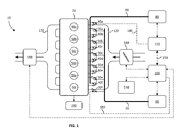
[0016] FIG. 1
is a schematic view of an engine system according to a first
embodiment comprising first injectors for a first fuel and second injectors
for a
second fuel; a first control unit controls a first fuel supply system and
actuates the first
injectors to introduce the first fuel into respective combustion chambers
through an
intake air system; a second control unit controls a second fuel supply system
and
actuates the second injectors to introduce the second fuel into respective
combustion
chambers through the intake air system.
[0017] FIG. 2 is a schematic view of an engine system according to a second
embodiment comprising first injectors for a first fuel and second injectors
for a
second fuel; a first control unit controls a first fuel supply system and
actuates the first
injectors to introduce the first fuel into respective combustion chambers
through an
intake air system; a second control unit controls a second fuel supply system
and
actuates the second injectors to introduce the second fuel into respective
combustion
chambers.
[0018] FIG. 3 is a schematic view of an engine system according to a third
embodiment comprising first injectors for a first fuel and second injectors
for a
second fuel; a first control unit controls a first fuel supply system and
actuates the first
CA 02931292 2016-05-20
WO 2015/074143
PCT/CA2014/051066
-7-
injectors to introduce the first fuel into respective combustion chambers; a
second
control unit controls a second fuel supply system and actuates the second
injectors to
introduce the second fuel into respective combustion chambers.
[0019] FIG. 4 is a schematic view of an engine system according to a fourth
embodiment comprising first injectors for a first fuel and second injectors
for a
second fuel; a first control unit controls a first fuel supply system and
actuates the first
injectors to introduce the first fuel into respective combustion chambers; a
second
control unit controls a second fuel supply system and actuates the second
injectors to
introduce the second fuel into respective combustion chambers through an
intake air
system.
[0020] FIG. 5 is a flow chart diagram of a first algorithm and a second
algorithm
for controlling the introduction of the first and second fuels into respective
combustion chambers of FIGS. 1 to 4 according to a first embodiment; the first
algorithm is performed by the first control unit and the second algorithm is
performed
by the second control unit.
[0021] FIG. 6 is a flow chart diagram of a first algorithm and a second
algorithm
for controlling the introduction of the first and second fuels into respective
combustion chambers of FIGS. 1 to 4 according to a second embodiment; the
first
algorithm is performed by the first control unit and the second algorithm is
performed
by the second control unit.
[0022] FIG. 7 is a flow chart diagram of a first algorithm and a second
algorithm
for controlling the introduction of the first and second fuels into respective
combustion chambers of FIGS. 1 to 4 according to a third embodiment; the first
algorithm is performed by the first control unit and the second algorithm is
performed
by the second control unit.
CA 02931292 2016-05-20
WO 2015/074143
PCT/CA2014/051066
-8-
Detailed Description of Preferred Embodiment(s)
[0023] Referring to FIG. 1, there is shown engine system 10 comprising engine
20
that can be fuelled with a first fuel and/or a second fuel according to a
first
embodiment. Engine 20 is a flexible fuel internal combustion engine that can
operate
in at least one of a dual fuel mode and a bi-fuel mode. In a preferred
embodiment the
first fuel is a liquid fuel and the second fuel is a gaseous fuel. A liquid
fuel is any fuel
that is in a liquid state at standard temperature and pressure, and a gaseous
fuel is any
fuel that is in a gas state at standard temperature and pressure. In the
context of this
application standard temperature and pressure are defined as a temperature of
20 C
and a pressure of 1 bar. Exemplary liquid fuels are gasoline, diesel, ethanol
and
mixtures of these fuels, and exemplary gaseous fuels are butane, ethane,
hydrogen,
methane, propane, natural gas and mixtures of these fuels, among others. By
way of
example, in a preferred embodiment the first fuel comprises gasoline and the
second
fuel comprises methane.
[0024] First
fuel supply system 60 supplies the first fuel through first fuel rail 70
to first fuel injectors 30a, 30b, 30c, 30d, 30e and 30f (30a-f). First control
unit 100 is
operatively connected with first fuel supply system 60 to monitor and control
the
delivery of the first fuel to first fuel rail 70. First control unit 100 is
further connected
with first fuel injectors 30a-f to actuate the first fuel injectors to
introduce the first
fuel into respective intake runners of intake manifold 120. Although only
connection
115 is illustrated between first control unit 100 and first fuel injector 30f,
it would be
known by those familiar with the technology that there would also be similar
connections between the first control unit and each one of first fuel
injectors 30a-e. In
the current embodiment first fuel injectors 30a-f are associated with
respective intake
runners and combustion chambers. In other embodiments one fuel injector can be
associated with two or more intake runners and combustion chambers such that
it is
located further upstream whereby the first fuel can be distributed to
respective intake
runners. First control unit 100 is further connected with engine sensors 130
representative of a variety of engine sensors that monitor engine status and
provide a
CA 02931292 2016-05-20
WO 2015/074143
PCT/CA2014/051066
-9-
plurality of signals to the first control unit representative of conventional
engine
parameters.
[0025] First control unit 100 can comprise both hardware and software
components. The hardware components can comprise digital and/or analog
electronic
components. In the embodiments herein first control unit 100 comprises a
processor
and memories, including one or more permanent memories, such as FLASH,
EEPROM and a hard disk, and a temporary memory, such as SRAM and DRAM, for
storing and executing a program. As used herein, the terms algorithm, module
and
step refer to an application specific integrated circuit (ASIC), an electronic
circuit, a
processor (shared, dedicated, or group) and memory that execute one or more
software or firmware programs, a combinational logic circuit, and/or other
suitable
components that provide the described functionality. The algorithms, modules
and
steps that are performed by first control unit 100 are part of the first
control unit.
[0026] Second
fuel supply system 80 supplies the second fuel through second fuel
rail 90 to second fuel injectors 40a, 40b, 40c, 40d, 40e and 40f (40a-f).
Second control
unit 110 is operatively connected with second fuel supply system 80 to monitor
and
control the delivery of the second fuel to second fuel rail 90. Sensors (not
shown) in
second fuel supply system 80 provide signals to second control unit 110
representative of second fuel supply parameters, such as for example the
temperature
and pressure of the second fuel, among others. Second control unit 110 is
further
connected with second fuel injectors 40a-f to actuate the second fuel
injectors to
introduce the second fuel into respective intake runners of intake manifold
120.
Although only connection 140 is illustrated between second control unit 110
and
second fuel injector 40a, it would be known by those familiar with the
technology that
there would also be similar connections between the second control unit and
each one
of second fuel injectors 40b-f. In the current embodiment second fuel
injectors 40a-f
are associated with respective intake runners and combustion chambers. In
other
embodiments one fuel injector can be associated with two or more intake
runners and
combustion chambers such that it is located further upstream whereby the
second fuel
can be distributed to respective intake runners. Second control unit 110 is
connected
CA 02931292 2016-05-20
WO 2015/074143
PCT/CA2014/051066
- 10 -
with first control unit 100 over communication line 150 such that information
can be
exchanged between the first and second control units. For example, first
control unit
100 can send current values of engine parameters, received from engine sensors
130
and/or calculated by the first control unit, to second control unit 110, and
the second
control unit can send second fuel supply parameters to the first control unit.
Communication line 150 can be an asynchronous communication bus or a
synchronous communication bus, and can be a dedicated link or shared link with
other
system control units. When communication line 150 is a dedicated link between
first
and second control units 100 and 110, a more advanced type of communication
line
can be selected, for desired features such as increased communication
bandwidth,
reliability and/or increased tolerance to noise, without substantially
increasing the cost
since other system control units (not shown) do not need to provide an
interface for
this dedicated link. Communication line 150 can be a controller area network
(CAN)
bus, an Ethernet bus, a FlexRay bus, a time-triggered protocol (TTP) bus, a
digital bus
such as I2C and SPI, and other standard and proprietary buses. In a
preferred
embodiment communication line 150 is a CAN bus.
[0027] Second control unit 110 can comprise both hardware and software
components. The hardware components can comprise digital and/or analog
electronic
components. In the embodiments herein second control unit 110 comprises a
processor and memories, including one or more permanent memories, such as
FLASH, EEPROM and a hard disk, and a temporary memory, such as SRAM and
DRAM, for storing and executing a program. As used herein, the terms
algorithm,
module and step refer to an application specific integrated circuit (ASIC), an
electronic circuit, a processor (shared, dedicated, or group) and memory that
execute
one or more software or firmware programs, a combinational logic circuit,
and/or
other suitable components that provide the described functionality. In
preferred
embodiments the algorithms, modules and steps that are performed by second
control
unit 110 are part of the second control unit.
[0028] Air is
delivered into intake manifold 120 through throttle 160. A fuel-air
charge is formed when the first fuel injected by first fuel injectors 30a-f
and/or the
CA 02931292 2016-05-20
WO 2015/074143
PCT/CA2014/051066
- 1 1 -
second fuel injected by second fuel injectors 40a-f mixes with the air. The
fuel-air
charge is drawn into combustion chambers 50a, 50b, 50c, 50d, 50e and 50f (50a-
f)
through intake ports located at respective ends of the intake runners adjacent
the
combustion chambers. In other preferred embodiments engine system 10 can
operate
in the Diesel-cycle without throttle 160. Although six combustion chambers 50a-
f are
illustrated, the techniques described herein apply to other embodiments where
there
are one or more combustion chambers. The fuel-air mixture is ignited causing
respective pistons (not shown) in combustion chambers 50a-f to reciprocate
thereby
imparting motive force to driveline 190 through a crankshaft (not shown)
operatively
connected with the pistons. Any ignition technique that can ignite the fuel-
air mixture
can be employed. Exhaust gases are directed out of combustion chambers 50a-f
through exhaust manifold 170 and engine after-treatment system 180. In
preferred
embodiments, first control unit 100 is operatively connected with engine after-
treatment system 180 to control the reduction of emissions. In other
embodiments
engine after-treatment system 180 may not be required if the emissions in the
exhaust
gases do not need to be reduced.
[0029] Referring now to FIG.2 there is shown engine system 12 according to a
second embodiment which is similar to the first embodiment where like parts in
this
embodiment and in all other embodiments have like reference numerals and may
not
be discussed in detail if at all. First fuel supply system 60 supplies the
first fuel
through first fuel rail 70 to first fuel injectors 30a-f, which are configured
to directly
introduce the first fuel into respective combustion chambers 50a-f in engine
22. In this
description "direct injection" and "injecting directly into the combustion
chamber" are
phrases that describe methods for injecting fuel into the combustion chamber
without
passing through the intake valve that regulates flow from the intake runner
into the
combustion chamber. Accordingly, herein directly injected fuel includes fuel
injected
through a fuel injector into the combustion chamber and fuel that is injected
into a
pre-chamber before being introduced into the combustion chamber. It would be
understood by someone skilled in the technology that first fuel injectors 30a-
f of FIG.
2 have different characteristics and specifications compared to first fuel
injectors 30a-
CA 02931292 2016-05-20
WO 2015/074143
PCT/CA2014/051066
- 12 -
f of FIG. 1, since there are different requirements for injecting fuel
directly into
combustion chambers compared to injecting fuel into an intake manifold.
Returning to
FIG. 2, since the first fuel is directly introduced into combustion chambers
50a-f, the
pressure of the first fuel and the timing at which the first fuel is
introduced may be
different than when the first fuel is introduced into intake manifold 120. As
a result,
first fuel supply system 60 of FIG. 2 may have different characteristics and
specifications compared to first fuel supply system 60 of FIG. 1.
[0030]
Referring now to FIG.3 there is shown engine system 13 according to a
third embodiment. First fuel supply system 60 supplies the first fuel through
first fuel
rail 70 to first fuel injectors 30a-f, which are configured to directly
introduce the first
fuel into respective combustion chambers 50a-f in engine 23. Second fuel
supply
system 80 supplies the second fuel through second fuel rail 90 to second fuel
injectors
40a-f, which are configured to directly introduce the second fuel into
respective
combustion chambers 50a-f in engine 23. It would be understood by someone
skilled
in the technology that second fuel injectors 40a-f of FIG. 3 have different
characteristics and specifications compared to second fuel injectors 40a-f of
FIG. 1,
since there are different requirements for injecting fuel directly into
combustion
chambers compared to injecting fuel into an intake manifold. Returning to FIG.
3,
since the second fuel is directly introduced into combustion chambers 50a-f,
the
pressure of the second fuel and the timing at which the second fuel is
introduced may
be different than when the second fuel is introduced into intake manifold 120.
As a
result, second fuel supply system 80 of FIG. 3 may have different
characteristics and
specifications compared to second fuel supply system 80 of FIG. 1.
[0031] Referring now to FIG.4 there is shown engine system 14 according to a
fourth embodiment. First fuel injectors 30a-f introduce the first fuel into
respective
intake runners of intake manifold 120, and second fuel injectors 40a-f
introduce the
second fuel directly into respective combustion chambers 50a-f.
[0032] Each of the embodiments illustrated in FIGS. 1 through 4 shows a
different arrangement for introducing the first and second fuels into
respective
CA 02931292 2016-05-20
WO 2015/074143
PCT/CA2014/051066
- 13 -
combustion chambers, and while these different arrangements may influence the
control strategies, the architecture for the control system is the same for
all
embodiments.
[0033] With reference to FIGS, a technique of operating engine systems 10, 12,
13 and 14 according to a first embodiment is now discussed. First algorithm
200,
performed by first control unit 100, determines total fuel energy amount (ET)
engines
20, 22, 23 and 24 are to be fuelled with to meet engine load and speed demand
and
actuates first fuel injectors 30a-f. Second algorithm 210, performed by second
control
unit 110, controls a first fraction of total fuel energy amount (ET) that is
to be from the
first fuel and a second fraction of total fuel energy amount (ET) that is to
be from the
second fuel and actuates second fuel injectors 40a-f. Demarcation line 205 is
representative of the boundary between algorithms 200 and 210, and the dashed
lines
crossing line 205 are representative of information transferred across
communication
line 150 between first and second control units 100 and 110 (seen in FIGS. 1,
2, 3 and
4).
[0034] In step 220, first algorithm 200 determines a fuel mass as a
function of
engine operating conditions that is representative of a first quantity of the
first fuel
and a second quantity of the second fuel. When the fuel mass is the first
quantity of
the first fuel it is further determined as a function of properties of the
first fuel, and
when the fuel mass is the second quantity of the second fuel it is further
determined as
a function of properties of the second fuel. The properties of the first and
second fuels
refer to physical and/or chemical properties of these fuels respectively. In a
preferred
embodiment the fuel mass is the first quantity of the first fuel such that
algorithm 200
does not require knowledge of the properties of the second fuel. The first
quantity is
an amount of the first fuel that engines 20, 22, 23 and 24 are to be fuelled
with to
meet engine load and speed demand without employing any of the second fuel.
The
second quantity is an amount of the second fuel that engines 20, 22, 23 and 24
are to
be fuelled with to meet engine load and speed demand without employing any of
the
first fuel. Similarly, the fuel mass is representative of total fuel energy
amount (ET)
required to meet engine load and speed demand. With reference to equation 1,
total
CA 02931292 2016-05-20
WO 2015/074143
PCT/CA2014/051066
- 14 -
fuel energy amount (ET) is equal to a first energy amount (E1) of the first
quantity of
the first fuel, and is also equal to a second energy amount (E2) of the second
quantity
of the second fuel. First and second energy amounts (E1) and (E2) represent
the energy
derived from the combustion of the first and second quantities of the first
and second
fuels respectively. The fuel mass, or the like, is communicated to second
control unit
110 via communication line 150 and the communication is represented by
information
transfer 300.
ET = E1 = E2 equation 1
[0035] Second
control unit 110 receives the fuel mass from first control unit 100,
and in step 230 second algorithm 210 determines a fuel fraction as a function
of at
least one of the fuel mass, engine operating conditions, properties of the
first fuel and
properties of the second fuel. For example, the fuel fraction can be
determined based
on time since engines 20, 22, 23 and 24 started, the temperature of first fuel
injectors
30a-f and second fuel injectors 40a-f (particularly when these injectors are
direct
injectors), user selection of fuel, total load, the quantity of the second
fuel remaining
(such as determined by second fuel pressure and/or level), by an output of a
vehicle
location module programmed to determine distance to fuelling stations for the
first
and/or second fuels, and by algorithms that improve engine and vehicle
operation
(fuel system protection, range improvement, cost per mile). If available it is
advantageous that second control unit 110 have knowledge of how engines 20,
22, 23
and 24 respond to the first fuel and the second fuel to more accurately
evaluate
equivalent energy at the crank output. In addition the air-fuel ratio for the
first fuel
can be different than the air-fuel ratio for the second fuel, which can
influence the fuel
fraction determination. The fuel fraction is representative of a third
quantity of the
first fuel that is to be injected by first fuel injectors 30a-f and a fourth
quantity of the
second fuel that is to be injected by second fuel injector 40a-f in one engine
cycle
respectively. In a preferred embodiment the fuel fraction is a ratio between
the third
and first quantities of the first fuel representing the fraction of the fuel
mass that is to
be injected by first fuel injectors 30a-f. The third quantity of the first
fuel has
associated with it third energy amount (E3), and the fourth quantity of the
second fuel
CA 02931292 2016-05-20
WO 2015/074143
PCT/CA2014/051066
- 15 -
has associated with it fourth energy amount (E4). Third and fourth energy
amounts
(E3) and (E4) represent the energy derived from the combustion of the third
and fourth
quantities of the first and second fuels respectively. The first, second,
third and fourth
quantities are associated with each other according to equation 2. First
energy amount
(E1) of the first quantity is equal to second energy amount (E2) of the second
quantity,
and both are equal to the sum of third energy amount (E3) of the third
quantity and
fourth energy amount (E4) of the fourth quantity, within a predetermined range
of
tolerance. The fuel fraction can be any parameter such that the third quantity
of the
first fuel and the fourth quantity of the second fuel can be determined when
knowing
the fuel mass, the properties of the first fuel and the properties of the
second fuel. For
example, the fuel fraction can be a first fraction of the first quantity, a
second fraction
of the second quantity, the third quantity of the first fuel, the fourth
quantity of the
second fuel, a first fraction of total fuel energy amount (ET) to be from the
first fuel, a
second fraction of total fuel energy amount (ET) to be from the second fuel, a
fraction
of first energy amount (E1), a fraction of second energy amount (E2), the
third energy
amount, the fourth energy amount, a ratio between the third and fourth
quantities, and
a ratio between the third and fourth energy amounts. The fuel fraction is
communicated to first control unit 110 via communication line 150 and the
communication is represented by information transfer 310.
ET = El = E2 = E3 E4 equation 2
[0036] First algorithm 200 calculates the third quantity of the first fuel
as a
function of at least two of the fuel mass, the fuel fraction, properties of
the first fuel
and properties of the second fuel in step 240, and in step 260 first pulse
widths for
actuating first fuel injectors 30a-f are determined based on the third
quantity. Second
algorithm 210 calculates the fourth quantity of the second fuel as a function
of at least
two of the fuel mass, the fuel fraction, properties of the first fuel and
properties of the
second fuel in step 250, and in step 270 second pulse widths for actuating
second fuel
injectors 40a-f are determined based on the fourth quantity. First fuel
injectors 30a-f
are actuated by first control unit 100 in step 280 and second fuel injectors
40a-f are
actuated by second control unit 110 in step 290.
CA 02931292 2016-05-20
WO 2015/074143
PCT/CA2014/051066
- 16 -
[0037] Referring now to FIG. 6, a technique for operating engine systems 10,
12,
13 and 14 according to a second embodiment that is similar to the previous
technique
of FIG. 5 is now discussed. First algorithm 201 is performed by first control
unit 100
and is similar to algorithm 200. Second algorithm 211 is performed by second
control
unit 110 and is similar to algorithm 210. In step 251, the fourth quantity of
the second
fuel is calculated as a function of the fuel mass, the fuel fraction and
properties of the
second fuel, which is similar to step 250. Additionally in step 251, the third
quantity
of the first fuel is calculated as a function of the fuel mass, the fuel
fraction and
properties of the first fuel. The third quantity of the first fuel is
communicated to first
control unit 100 via communication line 150 and the communication is
represented by
information transfer 311. The remaining steps in algorithms 201 and 211 are
similar
to those in algorithms 200 and 210.
[0038] Referring now to FIG. 7, another technique for operating engine systems
10, 12, 13 and 14 according to a third embodiment that is similar to the
previous
technique of FIG. 5 is now discussed. Step 221 is similar to previous step
220, but in
this embodiment the fuel mass, or the like, is not communicated to second
control unit
110. Step 231 is similar to previous step 230, but in this embodiment the fuel
fraction
is calculated as a function of at least one of engine operating conditions,
properties of
the first fuel and properties of the second fuel, but not as a function of the
fuel mass.
In step 241, the third quantity of the first fuel is calculated as a function
of the fuel
mass, the fuel fraction and properties of the first fuel, which is similar to
step 240.
Additionally in step 241, the fourth quantity of the second fuel is calculated
as a
function of the fuel mass, the fuel fraction and properties of the second
fuel. The
fourth quantity of the second fuel is communicated to second control unit 110
via
communication line 150 and the communication is represented by information
transfer 312. The remaining steps in algorithms 202 and 212 are similar to
those in
algorithms 200 and 210.
[0039] Additional information can be included in information transfers 310 and
311 of the heretofore described techniques of FIGS. 5, 6 and 7. Information
transfers
310 and 311 comprise communicating the fuel fraction to first control unit 100
from
CA 02931292 2016-05-20
WO 2015/074143
PCT/CA2014/051066
- 17-
second control unit 110. Additionally, timing information related to injection
of the
first fuel can be determined within second control unit 110 in steps 230 and
231, and
this timing information can be communicated to the first control unit 110 in
information transfers 310 and 311. The timing information related to injection
of the
first fuel can comprise start of injection timing, end of injection timing,
and number of
pulses (injection events). Normally, second control unit 110 does not comprise
knowledge regarding the characteristics of first fuel injectors 30a-f, and
therefore
pulse width information is not determined in second control unit 110.
[0040] Algorithms 200, 201 and 202 can be part of OEM control systems
deployed in first control unit 100. Algorithms 210, 211 and 212 can be part of
a
gaseous fuel control system deployed in second control unit 110. These
algorithms
have the advantages of requiring relatively few changes to the OEM control
systems,
which is advantageous for deploying such a control system with a variety of
engine
manufacturers to enable engines designed to operate only with conventional
liquid
fuel, to operate as a flexible fuel engine. Combustion control strategies in
the gaseous
fuel control system remain in second control unit 110 and do not need to be
deployed
to first control unit 100. First control unit 100 does not require hardware
changes
since sensor signals in second fuel supply system 80 do not need to be
received
directly by the first control unit and second fuel injectors 40a-f do not need
to be
actuated by the first control unit. Second control unit 110 receives these
sensor signals
and actuates the second fuel injectors. Furthermore, extra processing power
and/or
increased memory are not required for first control unit 100 since algorithms
210 and
211 are performed by second control unit 110. The information exchanged
between
first control unit 100 and second control unit 110 is over a CAN bus, in a
preferred
embodiment, which is already present in the majority of engines systems
currently
manufactured.
[0041] While particular elements, embodiments and applications of the present
invention have been shown and described, it will be understood, that the
invention is
not limited thereto since modifications can be made by those skilled in the
art without
CA 02931292 2016-05-20
WO 2015/074143
PCT/CA2014/051066
- 18 -
departing from the scope of the present disclosure, particularly in light of
the
foregoing teachings.