Note: Descriptions are shown in the official language in which they were submitted.
CA 02931391 2016-05-24
WO 2015/086557 PCT/EP2014/076972
1
TAP-HOLE REFURBISHING
Technical field
[0001] The present invention generally relates to a method for refurbishing
tap-
holes of arc furnaces, blast furnaces or smelter furnaces. Furthermore, the
present
invention relates to tap-hole inserts, which can be inserted into tap-hole
channels
of arc, blast or smelter furnaces to form refurbished tap-holes.
Background Art
[0002] It is well known within the art that tap-holes of arc furnaces, blast
furnaces
or smelter furnaces are exposed to extreme conditions. Molten slag and metal
are
discharged from such furnaces through one or more tap-holes arranged in the
lower section of the arc, blast or smelter furnace. Due to the high
temperatures
and the aggressive environment, the tap-hole wears out every time metal or
slag is
discharged. Therefore, each tap-hole can only be used for a limited number of
taps before it has to be replaced. In more severe processes, the tap-hole is
already worn-out after approximately 100 taps, which corresponds to 2 or 3
weeks
of continuous operation.
[0003] Currently, tap-holes are refurbished by rebuilding each tap-hole
manually
with preformed bricks, which are clayed in the worn-out tap-hole of the arc,
blast or
smelter furnaces to form a "refurbished" tap-hole. Prior to bringing new
bricks
manually into position, old bricks have to be removed from the surroundings of
the
hot tap-hole.
[0004] As every arc, blast or smelter furnace has to be shut down prior to
repairing the tap-holes, it is important that the repair is carried out as
fast as
possible. Cooling the arc, blast or smelter furnace down will require
additional
heating up time, which is an additional production and energy loss. Once
repaired,
the tap-hole needs to stay in working condition for as long as possible.
Therefore,
it is important that specialized craftsmen carry out the repair. Such
craftsmen are
difficult to find and their job is quite dangerous, since the old bricks and
the casing
of the arc, blast or smelter furnace are still very hot (about 500 C - 600 C)
even
when the arc, blast or smelter furnace has been shut down. To prevent the
CA 02931391 2016-05-24
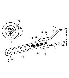
WO 2015/086557 PCT/EP2014/076972
2
craftsmen from being hurt, the procedure of repairing tap-holes has to be
carried
out very carefully.
[0005] As the craftsmen are working in a hazardous area, the preformed bricks
for refurbishing the tap-holes are often not well positioned. In consequence,
the
discharged metal or molten slag can get between the bricks, wash out the
filling
and dislodge them. Therefore tap-holes, which are refurbished with preformed
bricks, are not performing uniformly and may need to be replaced more
frequently.
[0006] GB2 203 526 describes a method to refurbish a plug fitted in the
sidewall
of a steel-making vessel where the refractory material sealing the plug in
place
has been burned off after a number of pourings to create an enlarged approach
well inside the steel-making vessel. A steel pipe is placed from the inside of
the
vessel in the worn plug using a boom and the steel pipe is sealed in place by
a
refractory material and the well is filled with settable refractory material
which
sinters or fuses with heat to effect the repair.
[0007] EP 0 726 439 describes a method of repairing a metallurgical vessel in
the
region of its tapping pipe, where a tapping pipe is inserted from below into
the
brickwork and held in place and then the gap between the pipe and the
brickwork
is filled from below with a filling material. Also disclosed is an arrangement
for
carrying out the method with a pressure plate on which the pipe can be placed,
with diameter greater than the outside diameter of the gap. The pressure plate
has
an aperture through which the filling material can be inserted.
[0008] JP2004218022 describes a method for repairing a blast furnace tap-hole,
comprising the steps of inserting a large block made of refractory for
repairing the
tap-hole. The block is a preformed two-layered structure which is set in
position by
press fitting the irregularly shaped refractory bricks into the region of the
large
block for repairing.
Technical problem
[0009] It is an object of the present invention to provide a method for
refurbishing
a tap-hole, which is faster and safer.
[0010] This object is achieved by a method for refurbishing a tap-hole as
claimed
in claim 1.
CA 02931391 2016-05-24
WO 2015/086557 PCT/EP2014/076972
3
General Description of the Invention
[0011] In order to overcome the above-mentioned problem, the present invention
comprises a method for refurbishing a tap-hole of an arc, blast or smelter
furnace.
The method for refurbishing a tap-hole comprises different steps.
[0012] In a first step, a tap-hole channel is made through the tap-hole block
in the
lower section of an arc, blast or smelter furnace. After a certain amount of
taps,
the tap-hole is worn-out due to erosion by the discharged molten metal and
slag.
To refurbish the tap-hole, the diameter of the worn-out tap-hole is increased
to
form a tap-hole channel. The increase in diameter of the tap-hole is
necessary,
since an insert with a greater outer diameter than the diameter of worn-out
tap-
hole is inserted into the tap-hole channel.
[0013] In a second step, a prefabricated, hollow, refractory tap-hole insert
comprising a shell with at least one lateral through hole is detachably
connected to
a clay gun. The tap-hole insert has a hollow passage with one axial opening
and at
least one lateral through hole.
[0014] The tap-hole insert is preferably cylindrically shaped with a circular
base.
Square refractory tap-hole inserts can be used too. In case a square
refractory
tap-hole insert is used, corners need to be removed manually in the newly
drilled
round tap-hole channel, which is easy to do as only a comparatively small wall
thickness is remaining.
[0015] After a tap-hole insert has been detachably connected to the clay gun,
the
tap-hole insert is inserted into the tap-hole channel. The tap-hole channel is
thus
fluidly coupled with the clay gun and the tap-hole insert because of the at
least one
lateral through hole in the shell of the tap-hole insert.
[0016] Thereafter, a grouting material arranged inside the clay gun is
injected
from the clay gun into the tap-hole insert and exits through the at least one
through
hole arranged in the shell of the tap-hole insert so as to completely fill the
gap
between the tap-hole channel and the tap-hole insert. The through holes end in
a
hollow section between the inner surface of the tap-hole channel and the outer
surface of the tap-hole insert. The thickness of the hollow section can be
determined by the outer diameter of the tap-hole insert and the diameter of
the
CA 02931391 2016-05-24
WO 2015/086557 PCT/EP2014/076972
4
tap-hole channel. The thickness of the hollow section is preferably in the
range of
40 to 100 mm. The clay gun injects grouting material through the tap-hole
insert
and the at least one through hole until the hollow section between the tap-
hole
channel and the outer surface of the shell of the tap-hole insert is
substantially
filled with the grouting material.
[0017] The clay gun is disconnected from the tap-hole insert before the
grouting
material has completely cured. Once cured, the tap-hole insert is solidly
fixed in
the tap-hole channel.
[0018] An advantage of the present method is that the refurbishing can be done
quickly and with a tool, which is readily available. Indeed because of the
through
hole in the tap-hole insert, the gap between the tap-hole channel and the tap-
hole
insert can easily be filled using the clay gun on which the tap-hole insert is
fastened and by which it is inserted into the tap-hole channel. The tap-hole
insert
is maintained securely in position during the filling of the gap with grouting
material
by the clay gun itself. Due the fact that the gap can now be filled through
the inside
of tap-hole insert, the tap-hole insert can remain attached and held in
position by
the clay gun during the operation. Nobody needs to be near the tap-hole during
the operation because the insertion and the filling of the gap between the tap-
hole
channel and the tap-hole insert is done via the clay gun. This method thus
considerably increases the safety of the workers during the operation.
[0019] A drill bit may subsequently be used to pierce the tap-hole insert and
thus
remove the grouting material injected in the tap-hole insert, such that molten
metal
and/or molten slag may subsequently be discharged from the arc, blast or
smelter
furnace.
[0020] Preferably, the tap-hole insert is detachably connected to the clay gun
by
an adapter. The adapter is detachably connected with one end to the clay gun
and
with another end to the tap-hole insert.
[0021] According to a preferred embodiment of the invention, an appropriate
grouting material is used for fixing the tap-hole insert to the tap-hole
channel.
Preferably, a grouting material is used that can be crafted (such as drilled)
easily.
The grouting material preferably comprises MgO or A1203 and withstands high
temperatures, which depend on the molten material requirements. The grain size
CA 02931391 2016-05-24
WO 2015/086557 PCT/EP2014/076972
of the grouting material is preferably smaller than the grain size of clay
materials,
which are usually used to seal the tap-holes. A particularly preferred
grouting
material such as e.g. Bauxite veneers CW610 or Phosphate moldables by
Sheffield Refractories can be used.
[0022] The method preferably comprises a step for inserting the insert until a
collar of the tap-hole insert abuts against the arc, blast or smelter furnace
outer
tap-hole block, which will normally not be replaced. Preferably, the collar is
configured so that no grouting material flows from the hollow passage past the
collar. Preferably, the tap-hole insert is thus pressed sealingly with its
collar
against the outer tap-hole block.
[0023] A metal tap-hole plate can be fixedly attached to the arc, blast or
smelter
furnace wall to hold the tap-hole insert in place. The metal tap-hole plate
can be
bolted or fixed by wedges onto the arc, blast or smelter furnace wall.
Alternatively,
a metal tap-hole plate can be positioned and latched at the end of the tap-
hole
insert, such that the tap-hole insert is kept in place.
[0024] According to a preferred embodiment of the invention, the making of the
tap-hole channel through the bottom section of the arc, blast or smelter
furnace
wall is carried out according to the following steps:
[0025] In a first step the tap-hole is opened with the first drill bit to
form a first
tap-hole opening with a first diameter. Preferably, the first drill bit used
for
opening the tap-hole is the same drill bit that is used for tapping.
[0026] Increase the first diameter of the tap-hole opening with a second drill
bit
to form a tap-hole channel, wherein the second drill bit is guided in the
first tap-
hole opening such that the tap-hole channel is collinear with the first tap-
hole
opening.
[0027] According to a preferred embodiment of the invention, additional drill
bits
are used to increase the diameter of the tap-hole channel. A third and/or
fourth drill
bit can be used to form a tap-hole channel. The first, the second, the third
and/or
fourth drill bits are detachably connected to a drilling hammer to form the
tap-hole
channel. Usually a drilling hammer is already provided for tapping the tap-
holes to
discharge molten metal and/or molten slag from the arc, blast or smelter
furnace.
CA 02931391 2016-05-24
WO 2015/086557 PCT/EP2014/076972
6
The same drilling hammer is used for powering different drill bits of
different
diameters. The second drill bit has a second diameter greater than the first
diameter of the first drill bit. The third drill bit has a third diameter
greater than the
second diameter of the second drill bit and fourth drill bit has a fourth
diameter
greater than the third diameter of the third drill bit.
[0028] According to a preferred embodiment of the invention, the first,
second,
third and/or fourth drill bits each have a drill area below or equal to a
maximum drill
capacity of the drilling hammer. The drill capacity is a maximum surface a
drilling
hammer is able to drill. In preference, a drill area of the first drill bit is
between 0,8
and 1,2 times a drill area of the second drill bit.
[0029] Advantageously, the second, third and/or fourth drill bits each have a
guiding section that is collinear with the first pilot opening and the tap-
hole
channel. The guiding section can be a cylindrical protrusion, which is
inserted into
the tap-hole opening and guides the drill bit.
[0030] Preferably, the first tap-hole opening is increased with a second drill
bit
having a second drilling diameter greater than the first diameter, the second
guiding section is inserted into the first tap-hole opening to guide the
second drill
bit to form a second tap-hole opening. The second tap-hole opening is
increased
with a third drill bit. The third drill bit has a third diameter greater than
the second
diameter. The making of a tap-hole channel can be carried out very fast. The
method is reliable and comparatively cheap, since only two additional drill
bits are
required.
[0031] Alternatively, the diameter of the worn-out tap-hole can be increased
by
removing adjacent bricks manually.
[0032] The prefabricated tap-hole insert comprises a shell, a base as well as
a
first end and a second end in axial direction wherein said second end is
blocked.
An opening is arranged in the first end, i.e. the end turned towards the clay
gun.
The tap-hole insert comprises a hollow passage in axial direction, which is
accessible through the opening in the first end. The tap-hole insert further
comprises at least one through hole, which is arranged in the shell of the tap-
hole
insert, such that the at least one through hole is in fluid communication with
the
hollow passage between the tap-hole insert and the tap-hole channel. The at
least
CA 02931391 2016-05-24
WO 2015/086557 PCT/EP2014/076972
7
one through hole is arranged laterally such, that a grouting material can be
injected through it with a clay gun so that the tap-hole insert can be fixed
in place
in the tap-hole channel. The person skilled in the art is able to arrange the
at least
one through hole such, that the pressure applied by a clay gun is sufficient
to inject
the grouting material through the at least one through hole.
[0033] The hollow passage in the tap-hole insert has multiple functions. The
hollow passage can be engaged by an adapter so as to detachably connect the
insert to a clay gun. Furthermore, the hollow passage is used as a channel for
guiding the grouting material that is injected therein to the at least one
through
hole. In addition, the inner circumference of the hollow passage substantially
corresponds to the diameter of the refurbished tap-hole opening. During the
tapping, the inner surface of the tap-hole insert is in direct contact with
the hot
molten material.
[0034] With the present tap-hole insert, the tap-holes can be refurbished
faster,
safer and more reliably than with traditional methods. The tap-hole inserts
can be
put in place very quickly, and the tap-holes, which are refurbished therewith
last
longer since they are positioned and sealed off under optimal conditions. Only
a
clay gun is required to put the tap-hole insert in place. As the clay gun is
already
available, no additional machinery is required for putting the tap-hole insert
in
place.
[0035] The tap-hole insert is closed at the second end, i.e. the end turned
towards the inside of the furnace so that no grouting material is injected
into the
arc, blast or smelter furnace. The pressure available for injecting the
grouting
material into the hollow section when the tap-hole insert has been inserted
can be
used more efficiently. Since the second end is closed, no molten material is
discharged through the refurbished tap-hole until the tap-hole has been tapped
for
the first time. As a result, multiple tap-holes can be refurbished and are
automatically closed when they have been refurbished.
[0036] The tap-hole insert is preferably pierced i.e. the grouting material
injected
in the previous step and the stopper closing the second end of the insert are
removed shortly after the insert has been placed in the furnace. The tap-hole
is
then closed again in the usual way with the clay gun and is then operational.
CA 02931391 2016-05-24
WO 2015/086557 PCT/EP2014/076972
8
[0037] According to a preferred embodiment of the invention, the tap-hole
insert
is made out of a refractory casting material, such as A1203 or MgO or
materials
with similar or equal qualities, and can thus be highly automated. A quality
control
can be implemented easily so as to assure a good product quality before the
tap-
hole insert is inserted into the tap-hole channel.
[0038] Preferably, a collar is arranged at or near the first end of the tap-
hole
insert. The collar is destined to abut against the outer surface of the arc,
blast or
smelter furnace wall when the tap-hole insert is completely inserted into the
opening.
[0039] Advantageously, the tap-hole insert has a length equal to or larger
than
the thickness of the arc, blast or smelter furnace wall. It may be preferable
to use a
tap-hole insert, which is longer then the thickness of the furnace wall so
that the
tap-hole insert protrudes inside the furnace. In this way, no turbulences near
the
furnace are created and the erosion of the furnace wall around the tap-hole is
reduced. The service life of the tap-hole is thus increased. Preferably, the
tap-hole
insert has a length between 800 and 1200 mm. It is preferably from 50 mm to
200
mm longer than the actual thickness of the furnace wall at the tap-hole.
[0040] Preferably the tap-hole insert has a plurality of through holes in
fluid
communication with the hollow passage which point in different radial
directions.
Advantageously, the tap-hole insert has a plurality of through holes, which
cover
between 10 and 25 % of the shell. Thanks to these through holes, the grouting
material can be distributed equally (homogenously) in the hollow annular
section.
[0041] According to a preferred embodiment of the invention, the hollow
passage
of the tap-hole insert has a diameter, which substantially corresponds to the
diameter of a refurbished tap-hole. The hollow passage may thus have a
diameter
between 10 and 30 mm.
[0042] The inner surface of the refurbished tap-hole is smooth, without any
grooves as the tap-hole insert is made of only one piece. Thanks to the
insert, the
refurbished tap-hole lasts longer than traditionally refurbished tap-holes.
[0043] The invention further relates to a method for closing a tap-hole. This
method is particularly useful with the refurbished tap-holes as described
above but
CA 02931391 2016-05-24
WO 2015/086557 PCT/EP2014/076972
9
it may also be used with any other tap-holes. The method comprises the
following
steps:
- detachably connecting a sealing rod to a clay gun,
- inserting the sealing rod into a tap-hole so that there is a space
between
the tap-hole and the sealing rod,
- injecting a clay material in the space between the tap-hole and the
sealing rod,
- holding the sealing rod in place until the clay material has at least
partially cured,
- disconnecting the sealing rod from the clay gun such that the sealing rod
remains in the tap-hole.
[0044] According to a preferred embodiment of the invention, the sealing rod
is
connected to the clay gun by a centering piece and said centering piece is
removed from the sealing rod while disconnecting the sealing rod from the clay
gun.
[0045] Preferably, the centering piece engages holding and retaining means of
the sealing rod to detachably connect to the sealing rod.
[0046] The sealing rod preferably further comprises a center hole for
centering
the drill bit to open the tap-hole channel.
Brief Description of the Drawings
[0047] Further details and advantages of the present invention will be
apparent
from the following detailed description of a non limiting embodiment with
reference
to the attached drawings, wherein:
Fig. 1 is a schematic cross sectional view of a preferred tap-hole insert;
Fig. 2 is an axial section of a sealing rod, which has been inserted into the
tap-
hole;
Fig. 3 is a cross-sectional view of an inserted sealing rod;
Fig. 4 is a schematic projection of a centering piece according to a preferred
embodiment of the invention; and
CA 02931391 2016-05-24
WO 2015/086557 PCT/EP2014/076972
Fig. 5 is a schematic projection of a sealing rod according to a preferred
embodiment of the invention.
Description of Preferred Embodiments
[0048] In the following, a method for refurbishing a tap-hole according to a
preferred embodiment of the invention is described. The method for
refurbishing a
tap-hole comprises multiple steps.
[0049] In a first step, a tap-hole opening is made for receiving a new tap-
hole
insert 2. The new tap-hole opening is preferably placed in the same spot in
the
lower section of the arc, blast or smelter furnace as the old worn-out tap-
hole.
According to a preferred embodiment of the invention, a drilling hammer, which
is
brought in place outside of the arc, blast or smelter furnace, increases the
diameter of the old worn-out tap-hole by drilling a tap-hole channel that
receives
the tap-hole insert 2. As the diameter of the required tap-hole channel
(between
150 mm or 250 mm) is larger than the diameter of the worn-out tap-hole, the
tap-
hole drilling hammers, which are used for tapping arc, blast or smelter
furnaces do
not usually provide the necessary power to bore an opening of a diameter of
150
mm or 250 mm or larger.
[0050] Therefore, the tap-hole channel is drilled out by using well-graded
drill bits
of different diameters. The first drill bit has the smallest outer diameter,
which is
equal to approximately 80 mm and forms a first tap-hole opening. Drill bits of
this
size are primarily used for opening blind tap-holes or for draining the slag
or pig
iron. In this case, the first tap-hole opening is used as a first pilot
opening for
receiving the second guiding section of the second drill bit. After the first
opening
has been drilled, the first drill bit is removed from the first opening and
the first drill
bit is detached from the drilling hammer. Subsequently, a second drill bit is
attached to the drilling hammer. The second drill bit comprises a second drill
section with an outer diameter of approximately 120 mm and a second guiding
section, with a diameter of approximately 80 mm. The diameter of the second
guiding section is substantially equal to the diameter of the first opening.
The
second guiding section protrudes into the first opening and serves as a
centering
device for drilling the second pilot opening, such that the second opening is
collinear with the first opening. After the first opening has been increased
to a
CA 02931391 2016-05-24
WO 2015/086557 PCT/EP2014/076972
11
diameter of 120 mm, the second drill bit is removed from the second opening
and
detached from the drilling hammer.
[0051] A third drill bit is attached to the drilling hammer. The third drill
bit
comprises a third drill section with an outer diameter of approximately 150 mm
and
a third guiding section with a diameter of approximately 120 mm. The third
drill bit
is inserted with its third guiding section in the second opening. The diameter
of the
second opening is increased to approximately 150 mm to form the tap-hole
channel. After having finished with the drilling of the tap-hole channel, the
drilling
hammer is removed from the access area of the tap-hole channel.
[0052] The first guiding opening, the second guiding opening and the tap-hole
channel are holes, which extend through the tap-hole block of the arc, blast
or
smelter furnace. The person skilled in the art chooses the material of the
drill bits
according to the material of the tap-hole block. Even if the arc, blast or
smelter
furnace is empty, before the first step is executed, the temperature inside
the
furnace is still very high. Therefore, the drill bits need to be chosen
carefully.
Preferably, the drill bits are made of a material that can withstand these
high
temperatures. It is important that the drilling is executed as fast as
possible to
prevent the arc, blast or smelter furnace from cooling down too much. As long
as
the drilling surface is equal or inferior to the drilling capacity of the
drilling hammer,
the drilling can be carried out quickly and safely. Preferably, all of the
drill bits are
chosen such that the drill area of each bit equals the maximum drilling
capacity of
the drilling hammer.
[0053] The only parts that have to be additionally purchased to carry out the
drilling are the second and the third drill bits. The first drill bit and the
drilling
hammer are already available, since they have been used to open closed tap-
holes before. The second and the third drill bit are comparatively inexpensive
when compared to a new drilling hammer with higher drilling capacity. The
method
of opening the tap-hole by modifying machinery that is mostly already provided
is
faster and more secure than currently used methods, such as e.g. manual labor.
Production losses are hence reduced and less energy is required for
reestablishing the normal arc, blast or smelter furnace operation temperature.
CA 02931391 2016-05-24
WO 2015/086557 PCT/EP2014/076972
12
[0054] In a next step, the tap-hole insert 2 is detachably connected to a clay
gun
4 by means of an adapter 6. The adapter 6 engages the tap-hole insert 2, such
that it is held in place until the tap-hole insert 2 is installed in the tap-
hole opening.
[0055] The tap-hole insert 2 is made of a precast refractory, preferably
comprising
A1203 or MgO or materials with similar or equal qualities. The person skilled
in the
art selects the material to form the precast refractory from the materials
that are
known to withstand the conditions of the metallurgical process in the arc,
blast or
smelter furnace.
[0056] The tap-hole insert 2 has the shape of a hollow cylinder with a
circular
base. On one end, the hollow cylinder has an opening to a hollow passage 10
and
one collar 8 with an outer collar diameter, which is larger than the diameter
of the
tap-hole opening. The tap-hole insert 2 is inserted into the tap-hole channel,
such
that the tap-hole collar 8 abuts against the tap-hole block of the arc or
smelter
furnace. On the other end, the tap-hole insert 2 is closed so that no fluid
can exit
the hollow passage in axial direction.
[0057] The outer diameter of the circular base is substantially equal to or
smaller
than the diameter of the tap-hole channel, such that it can be inserted into
the tap-
hole channel. The diameter of the hollow passage is substantially equal to the
inner diameter of the "refurbished" tap-hole. The tap-hole insert has a
length,
which is substantially equal to or greater than the tap-hole block. The length
of the
tap-hole block is preferably between 800 and 1200 mm. It is particularly
preferred
that the length is chosen to be greater, such as from 50 mm to 200 mm longer,
than the actual thickness of the furnace wall at the tap-hole. As a result,
while
molten metal is discharged from the arc, blast or smelter furnace through the
tap-
hole insert, the tap-hole block does not wear out.
[0058] Through holes 12 are arranged in the shell of the tap-hole insert so
that
they are pointing in a first radial direction and aligned in a longitudinal
direction of
the cylinder, with a first constant interval in-between. The amount of through
holes
12 will depend on the grouting composition, its viscosity and its grain size..
Advantageously, the cylinder has a second line of radial through holes 12
pointing
in a second radial direction, aligned in the longitudinal direction of the
cylinder with
a second constant interval in between. The first constant interval can be
equal to
CA 02931391 2016-05-24
WO 2015/086557 PCT/EP2014/076972
13
the second constant interval, while the first line of radial through holes 12
is set off
by half the first constant interval from the second line of radial orifices in
the
longitudinal direction of the cylinder. The second line of radial through
holes 12 is
pointing in a second radial direction with an angle a of 900 to the first
radial
direction. The first and the second line of radial through holes 12 are also
arranged
on the opposite side of the tap-hole insert. They are arranged such that the
grouting material can be injected and distributed easily and evenly in the
annular
hollow section without clogging. The diameter of each through hole 12 is for
this
particular advantageous embodiment in the range between 10 mm and 30 mm.
The diameter of through holes 12 is chosen according to the grouting material,
to
the size of the substantially annular hollow section and to the maximum
pressure
that is applied onto the grouting material by the clay gun. At least 10-25% of
the
shell of the tap-hole insert is covered with through holes.
[0059] The through holes 12 can be bored into tap-hole insert 2 after the
casting
process.
[0060] The adapter element 6 is detachably connected with the first end to the
clay gun and with the second end to the tap-hole insert 2. The adapter element
6
comprises a tube 14, which allows the passage of the grouting material from
the
clay gun to the hollow passage 10 of the tap-hole insert.
[0061] Three or more first spokes 16 are arranged on the circumference of the
hollow tube 6, preferably distributed with equal spacing between the first
spokes
16 on the circumference of the first end of the hollow tube 6. The first
spokes 16
detachably connect the hollow passage 10 with the clay gun. Each of the three
or
more first spokes 16 is a rectangular cuboid with a first height, a first
length and a
first thickness. The first height corresponds to the distance between the
circumference tube and the inner surface of the mouthpiece 18 of the clay gun
4.
The first length is chosen such that the first spokes 16 can withstand the
momentum and radial stress applied thereon by the weight of the tap-hole
insert 2.
The thickness of each of the at least three or more first spokes 16 is chosen
such
that there is a hollow space between the one or more first spokes 16.
[0062] Three or more second spokes 20 are arranged on the circumference of the
hollow tube 14, preferably distributed with equal spacing between the second
CA 02931391 2016-05-24
WO 2015/086557 PCT/EP2014/076972
14
spokes 20 on the circumference of the second end of the tube 14. The second
spokes 20 detachably connect the tube 14 with the tap-hole insert 2. Each of
the
two or more second spokes 20 is a rectangular cuboid with a second height, a
second length and a second thickness. The second height corresponds to the
distance between the circumference of the tube 14 and the inner surface of the
hollow passage 10. The second length is chosen such that the second spokes 20
can withstand the momentum and radial stress applied thereon by the weight of
the tap-hole insert 2. The thickness of each of the at least two or more
second
spokes 20 is chosen such that there is a hollow space between the one or more
second spokes 20.
[0063] The outer diameter of the tube 14 can be adapted to reduce the amount
of
grouting material that remains between the inner surface of the tap-hole
insert and
the outer surface of the hollow tube. This is advantageous since less
auxiliary
grouting material has to be removed from the inner surface of the tap-hole
insert.
[0064] In a next step, the tap-hole insert 2 is inserted into the tap-hole
channel.
For inserting the tap-hole insert 2, a clay gun 4 is put in place, outside of
the arc,
blast or smelter furnace such that the clay gun 4 can access the tap-hole
opening.
[0065] After having inserted the tap-hole insert 2 into the tap-hole channel,
a
grouting material is injected from the clay gun 4 into the hollow passage 10
and
through the through holes 12 so as to fill the space between the outer
circumference of the tap-hole insert 2 and the tap-hole channel. The grouting
material between the outer circumference of the tap-hole insert 2 and the
inner
surface of the tap-hole channel hardens while the tap-hole insert 2 is held in
position. The clay gun 4 is removed before the grouting material has cured.
[0066] Preferably, a grouting material, such as plaster is used for this
operation
as other grouting materials may be too stiff for the injection and tend to
clog inside
the tap-hole insert 2. It is preferable to choose a grouting material fills up
easily the
gap between the new tap-hole insert and the outer tap-hole refractory.
[0067] For opening the refurbished tap-hole, the drilling hammer is put in
place
with the first drill bit attached thereon. The refurbished tap-hole opening
(which
has substantially the same diameter as the hollow passage of the insert) is
drilled
with the first drill bit. The final drilling removes any residual hardened
grouting
CA 02931391 2016-05-24
WO 2015/086557 PCT/EP2014/076972
materials from the interior of the tube and opens the closed second end of the
tap-
hole insert 2. After the final drilling, the tap-hole insert 2 allows
transmission of
fluids from the interior of the arc, blast or smelter furnace to the exterior
of the
furnace.
[0068] The method is very time saving compared to currently performed methods.
It is highly automated and can be carried out without the need of manual
labor. As
a result, no person is exposed to a hazardous area.
[0069] The refurbished tap-hole is of very high quality, since the materials
for
repairing the tap-hole can be optimally placed and the materials can be chosen
carefully. Quality control can be carried out before the tap-hole insert 2 is
inserted
into the tap-hole channel. This is in contrast to manually refurbished tap-
holes,
where the preformed bricks are often not optimally placed and where no quality
control can be carried out before the preformed bricks are put in place.
[0070] The invention further relates to a sealing rod 100 and a method for
inserting such a sealing rod 100 into the tap-hole 102 before the clay
material is
injected therein.
[0071] The sealing rod 100 in fig. 3 can be used to seal any tap-holes 102,
including tap-holes, which have been refurbished with tap-hole inserts 2.
[0072] The sealing rod 100 is a cylinder with a length l_sr, which is
preferably
greater than the length of the tap-hole channel 102 or the tap-hole insert 2.
The
length of the sealing rod 100 is in a range between 0.8 m and 1.5 m. The
diameter
of the sealing rod 100 is preferably between 40 mm and 80 mm.
[0073] The sealing rod 100 is preferably made of refractory material. The
mechanical properties of the sealing rod material are similar to the
mechanical
properties of the clay material once the clay material has hardened. Since
less
clay is put around the sealing rod 100, the clay hardens faster compared to
traditional methods.
[0074] The sealing rod 100 has a diameter d_sr preferably between 40 mm and
80 mm between a first end 104, which comprises a collar 106 and a second end
108, which comprises a taper 110. When the sealing rod 100 is inserted into
the
arc, blast or smelter furnace wall, the second end 108 with the taper 110
CA 02931391 2016-05-24
WO 2015/086557 PCT/EP2014/076972
16
penetrates axially into the tap-hole 102 until the first end 104 with the
collar 106 is
substantially flush with the external surface of the furnace wall. The taper
110
simplifies the insertion of the sealing rod 100 into the tap-hole 102. The
collar 106
is chosen to sealingly engage the clay gun 114 and the outer surface of the
tap-
hole block 112. No clay can escape between the clay gun 114 and the wall of
the
arc, blast or smelter furnace.
[0075] The sealing rod 100 comprises holding and retaining means for
detachably
engaging a centering piece 118. According to a preferred embodiment of the
invention, the holding and retaining means are a central borehole 116, which
is
coaxial with the central axis of the sealing rod 100. The central borehole 116
is
accessible from the first end 104 of the sealing rod 100 where the collar 106
is
located. The length of the borehole 116 is preferably between 0.25 and 0.5
times
the length of the sealing rod 100 and has a diameter between 15 mm to 20 mm.
[0076] Firstly, the borehole 116 serves to detachably connect the sealing rod
100
to the centering piece 114 and thereby to the clay gun 114. The centering
piece
118 is inserted into the borehole 116 of the sealing rod 100 to manipulate the
sealing rod 100 such that it can be easily inserted into the tap-hole 102
using the
clay gun 114 and to hold the sealing rod 100 inside the tap-hole 102 until the
clay
material around the sealing rod 100 has at least partially cured. The diameter
of
the borehole 116 is chosen such that it can engage the centering piece 118.
The
centering piece 118 is dimensioned to be able to resist the weight of the
sealing
rod 100.
[0077] Secondly, the borehole 116 can serve as a centering hole for a drill
bit
when the tap-hole 102 is reopened to tap the liquid metal or slag from the
arc,
blast or smelter furnace. As a result, the sealing rod 100 can be drilled more
easily
and more accurately.
[0078] Alternatively, the borehole 116 can also be placed eccentrically with
regard to the central axis of the sealing rod 100. In this case the borehole
116
would not be used as a centering hole for a drill bit to reopen the tap-hole
102.
[0079] The collar 106 in figs. 3, 4 and 5 comprises one or more openings so
that
the clay from the clay gun 114 can be injected into the space between the tap-
hole
102 wall and the sealing rod 100. These openings are configured and
CA 02931391 2016-05-24
WO 2015/086557 PCT/EP2014/076972
17
dimensioned so as not to put too much resistance to the flow of the clay from
the
clay gun 114.
[0080] The openings are preferably eccentric with regard to the central axis
of the
sealing rod 100. According to a particular preferred embodiment of the
invention,
the openings are cut-outs 119, 119', 119". As a consequence, the collar 106 is
formed by three bars 120, 120', 120" that extend perpendicularly from the
central
axis of the sealing rod 100. The surface of the cut-outs 119, 119', 119" is
slightly
bigger in size than the surface of the bars 120, 120', 120". The bigger the
size of
the cut-outs 119, 119', 119" the easier the clay can be injected into the
space
between the tap-hole 102 wall and the sealing rod 100. However, they must be
dimensioned so that the sealing rod can be manipulated safely with the clay
gun
114.
[0081] According to a preferred embodiment of the invention the cut-outs cover
between 10% to 80% of the collar's 106 surface. Each one of the bars 120,
120',
120" in fig. 6 points in a radial direction away from the central axis of the
sealing
rod 100. The bars 120, 120', 120" are spaced one from another by an angle a of
approximately 120 . Each bar 120, 120', 120" has a thickness of 15-20 mm and a
length of 30-50 mm and is manufactured in one piece with the sealing rod 100.
The width of the bars 120, 120', 120" is preferably 2-4 times greater than the
thickness. Each bar 120, 120', 120" is slightly curved on the extremity. The
curve
on the extremity corresponds to the course of a circle with a diameter equal
to the
length of the bar 120, 120', 120".
[0082] The centering piece 118 in fig. 5 comprises a first cylinder 122, which
is
insertable into the borehole 116 of the sealing rod 100.
[0083] The centering piece 118 is preferably made of steel and withstands the
momentum and the shear stress applied thereon by the sealing rod 100.
[0084] A second cylinder 124 of a larger diameter than or an equal diameter to
the diameter of the first cylinder 122 is arranged on one end of the first
cylinder
122. Three fins 126, 126', 126" are arranged in three different radial
positions on
the second cylinder 124 over its circumference. The angle between neighboring
fins 126, 126', 126" is equal to an angle [3 of approximately 120 . Each fin
126,
CA 02931391 2016-05-24
WO 2015/086557 PCT/EP2014/076972
18
126', 126" has a thickness of 15-20 mm and a length of 20-40 mm along the
direction of the central axis.
[0085] The centering piece 118 is inserted into the borehole 116 until the
second
cylinder 124 or the fins 126, 126', 126" abut with the collar 106 respectively
with
the bar 120, 120', 120" of the sealing rod 100. When the centering piece 118
is
engaged into the borehole 116 of the sealing rod 100, the fins 126, 126', 126"
of
the centering piece 118 are aligned with the bars 120, 120', 120" of the
collar 106
of the sealing rod 100 so as to minimize the resistance to the flow of clay
from the
clay gun 114.
[0086] The fins 126, 126', 126" and the end 128 of the cylinder 124 is also
tapered in the direction of the clay gun 124, when the centering piece 118 is
connected to the clay gun 124. The tapered fins 126, 126', 126" and the
tapered
end 128 are thus shaped to decrease the pressure of the clay material on the
centering piece 118 during injection. The fins 126, 126', 126" are dimensioned
so
that they engage the clay gun 114 and assure a mechanical connection between
the centering piece 118 and the clay gun 114. The fins 126, 126', 126" are
shaped
to engage the clay gun 114 and to withstand the momentum and the shear stress
applied onto the centering piece 118 by manipulating the sealing rod 100.
[0087] The opening of the clay gun 114 through which the clay is injected in
the
tap-hole has a diameter between 100 mm and 150 mm. Since the diameter of the
centering piece 118 is between 15 mm to 20 mm and the thickness of the fins
126,
126', 126" in the direction of the flow of the clay is between 15 and 20 mm,
there is
enough room for the clay to be injected efficiently into the tap-hole 102.
[0088] When the centering piece 118 and the sealing rod 100 are assembled,
each fin 126, 126', 126" and each bar 120, 120', 120" are preferably aligned
in the
axial direction, as shown in fig. 4. As a result, the passageway for the clay
material
through the cut-outs 119, 119', 119" is open and the fins 126, 126', 126"
and/or
the bar 120, 120', 120" do not block the flow of the clay material more than
necessary.
[0089] In the following, a method according to the invention to seal a tap-
hole 102
will be described. The sealing rod 100 can be used to seal any tap-holes.
CA 02931391 2016-05-24
WO 2015/086557 PCT/EP2014/076972
19
[0090] In case the sealing rod 100 is used in combination with a tap-hole
insert 2,
the sealing rod 100 is placed into the tap-hole insert 2 after the grouting
material
inside the tap-hole 102 has been pierced. The subsequent steps of a method for
sealing a tap-hole 102 without a tap-hole insert 2 are the same as the steps
of a
method for sealing a tap-hole 102 with a tap-hole insert 2.
[0091] The method for inserting the sealing rod 100 into the tap-hole 102
comprises the following steps:
[0092] In a first step, the centering piece 122 is inserted into the clay gun
114
with three fins 126, 126', 126" mechanically engaging the inner wall of the
clay
gun 114. The first cylinder 122 of the centering piece 122 is inserted into
the
borehole 116 of the sealing rod 100 in such a way that the clay gun 114 can be
used to manipulate the sealing rod 100.
[0093] As the taper 110 of the sealing rod 100 is arranged on the opposite end
of
the collar 106 on the sealing rod 100, the taper penetrates first into the tap-
hole
102 until the clay gun 114 abuts against the tap-hole block 112.
[0094] The clay gun 114 presses the collar 106 against the outer surface of
the
tap-hole block 112. As the taper 110 has the shape of a frustum of a circular
cone
it is easier to insert the sealing rod 100 into the tap-hole channel 102. The
diameter of the frustum of the circular cone diminishes towards the tip of the
sealing rod 100.
[0095] A clay material is injected from the clay gun 114 into the annular
cavity
between the tap-hole 102 and the sealing rod 100 along the fins 126, 126',
126" of
the centering piece 118 and through the cut-outs 119, 119', 119" of the
sealing rod
100. If there is any liquid remaining in the tap-hole 102, the injected clay
material
pushes it back.
[0096] After the clay material has partly hardened, the clay gun 114 is
withdrawn
and the centering piece 118 is removed from the sealing rod 100. The clay
requires about 1 to 2 minutes to harden. Thereafter, the centering piece 118
disengages the sealing rod 100 and the sealing rod 100 stays inside the tap-
hole
102 until the tap-hole 102 is reopened with a drilling hammer. The drill bit
of the
drilling hammer, which is used to pierce the tap-hole 102 has a slightly
larger
CA 02931391 2016-05-24
WO 2015/086557 PCT/EP2014/076972
diameter than the diameter d_sr of the sealing rod 100. The diameter of the
drill bit
is preferably between 5% to 10% bigger than the diameter of the sealing rod
100.
A part or all of the clay that has been injected to fix the sealing rod 100 in
the tap-
hole 103 is removed with the drilling hammer. As a result, a new sealing rod
with
the same diameter than the previous sealing rod 100 can be used to seal the
tap-
hole 102 of the arc, blast or smelter furnace.
[0097] Once the tapping of the furnace is finished, a new sealing rod 100 can
be
placed into the tap-hole 102.
[0098] The method is advantageous compared to other methods, which do not
rely on sealing rods 100. When no sealing rod 100 is used to close the tap-
hole
102, metal or slag can remain or penetrate in the tap-hole 102 and solidify
therein.
Once this material has solidified, it is difficult to reopen the tap-hole 102
with
standard drilling equipment because this material is much harder than the clay
used to seal the tap-hole. When inserting the sealing rod, any metal or slag,
which
may be in the tap-hole, will be pushed back in the furnace.
[0099] The tap-hole 102 can be reopened easily if a method for closing the tap-
hole 102 as described above is used. The material, which has to be removed
from
the tap-hole 102 is mainly the sealing rod 100 and a little clay material,
which has
been injected in the space between the tap-hole and the sealing rod. Even if
metal
or slag penetrates the space between the sealing rod 100 and the tap-hole 102
the
quantity of this material is so small that the drilling operation can be made
without
problems with the standard equipment.
[00100] Furthermore, substantially less clay material is used to seal the
tap-hole 102 with a sealing rod 100 according to the invention.
CA 02931391 2016-05-24
WO 2015/086557
PCT/EP2014/076972
21
Legend:
2 tap-hole insert
4 clay gun
6 adapter element
8 collar
hollow passage
12 through holes
14 tube
16 first spokes
18 mouthpiece
second spokes
100 sealing rod
102 tap-hole
104 first end
106 collar
108 second end
110 taper
112 tap-hole block
114 clay gun
116 holder
118 centering piece
120, 120', 120" bar
122 first cylinder
124 other cylinder
126, 126', 126" fin
128 tapered end