Note: Descriptions are shown in the official language in which they were submitted.
CA 02931556 2016-05-27
ELECTROMAGNETIC TELEMETRY SYSTEM WITH COMPENSATION
FOR DRILLING FLUID CHARACTERISTICS
Technical Field
[0001] This application relates to subsurface drilling, specifically to an
electromagnetic
telemetry system with compensation for drilling fluid characteristics.
Embodiments are
applicable to drilling wells for recovering hydrocarbons.
Background
[0002] Recovering hydrocarbons from subterranean zones typically involves
drilling
wellbores.
[0003] Wellbores are made using surface-located drilling equipment which
drives a drill
string that eventually extends from the surface equipment to the formation or
subterranean
zone of interest. The drill string can extend thousands of feet or meters
below the surface.
The terminal end of the drill string includes a drill bit for drilling (or
extending) the
wellbore. Drilling fluid, usually in the form of a drilling "mud", is
typically pumped
through the drill string. The drilling fluid cools and lubricates the drill
bit and also carries
cuttings back to the surface. Drilling fluid may also be used to help control
bottom hole
pressure to inhibit hydrocarbon influx from the formation into the wellbore
and potential
blow out at surface.
[0004] Bottom hole assembly (BHA) is the name given to the equipment at the
terminal
end of a drill string. In addition to a drill bit, a BHA may comprise elements
such as:
apparatus for steering the direction of the drilling (e.g. a steerable
downhole mud motor or
rotary steerable system); sensors for measuring properties of the surrounding
geological
formations (e.g. sensors for use in well logging); sensors for measuring
downhole
conditions as drilling progresses; one or more systems for telemetry of data
to the surface;
stabilizers; heavy weight drill collars; pulsers; and the like. The BHA is
typically
advanced into the wellbore by a string of metallic tubulars (drill pipe).
- 1 -
CA 02931556 2016-05-27
[0005] Modern drilling systems may include any of a wide range of
mechanical/electronic
systems in the BHA or at other downhole locations. Such electronics systems
may be
packaged as part of a downhole probe. A downhole probe may comprise any active
mechanical, electronic, and/or electromechanical system that operates
downhole. A probe
may provide any of a wide range of functions including, without limitation:
data
acquisition; measuring properties of the surrounding geological formations
(e.g. well
logging); measuring downhole conditions as drilling progresses; controlling
downhole
equipment; monitoring status of downhole equipment; directional drilling
applications;
measuring while drilling (MWD) applications; logging while drilling (LWD)
applications;
measuring properties of downhole fluids; and the like. A probe may comprise
one or more
systems for: telemetry of data to the surface; collecting data by way of
sensors (e.g.
sensors for use in well logging) that may include one or more of vibration
sensors,
magnetometers, inclinometers, accelerometers, nuclear particle detectors,
electromagnetic
detectors, acoustic detectors, and others; acquiring images; measuring fluid
flow;
determining directions; emitting signals, particles or fields for detection by
other devices;
interfacing to other downhole equipment; sampling downhole fluids; etc. A
downhole
probe is typically suspended in a bore of a drill string near the drill bit.
Some downhole
probes are highly specialized and expensive.
[0006] A downhole probe may communicate a wide range of information to the
surface by
telemetry. Telemetry information can be invaluable for efficient drilling
operations. For
example, telemetry information may be used by a drill rig crew to make
decisions about
controlling and steering the drill bit to optimize the drilling speed and
trajectory based on
numerous factors, including legal boundaries, locations of existing wells,
formation
properties, hydrocarbon size and location, etc. A crew may make intentional
deviations
from the planned path as necessary based on information gathered from downhole
sensors
and transmitted to the surface by telemetry during the drilling process. The
ability to
obtain and transmit reliable data from downhole locations allows for
relatively more
economical and more efficient drilling operations.
[0007] There are several known telemetry techniques. These include
transmitting
information by generating vibrations in fluid in the bore hole (e.g. acoustic
telemetry or
mud pulse (MP) telemetry) and transmitting information by way of
electromagnetic
- 2 -
CA 02931556 2016-05-27
signals that propagate at least in part through the earth (EM telemetry).
Other telemetry
techniques use hardwired drill pipe, fibre optic cable, or drill collar
acoustic telemetry to
carry data to the surface.
100081 Advantages of EM telemetry, relative to MP telemetry, include generally
faster
baud rates, increased reliability due to no moving downhole parts, high
resistance to lost
circulating material (LCM) use, and suitability for air/underbalanced
drilling. An EM
system can transmit data without a continuous fluid column; hence it is useful
when there
is no drilling fluid flowing. This is advantageous when a drill crew is adding
a new
section of drill pipe as the EM signal can transmit information (e.g.
directional
information) while the drill crew is adding the new pipe. Disadvantages of EM
telemetry
include lower depth capability, incompatibility with some formations (for
example, high
salt formations and formations of high resistivity contrast), and some market
resistance
due to acceptance of older established methods. Also, as the EM transmission
is strongly
attenuated over long distances through the earth formations, it requires a
relatively large
amount of power so that the signals are detected at surface. The electrical
power available
to generate EM signals may be provided by batteries or another power source
that has
limited capacity.
100091 A typical arrangement for electromagnetic telemetry uses parts of the
drill string as
an antenna. The drill string may be divided into two conductive sections by
including an
insulating joint or connector (a "gap sub") in the drill string. The gap sub
is typically
placed at the top of a bottom hole assembly such that metallic drill pipe in
the drill string
above the BHA serves as one antenna element and metallic sections in the BHA
serve as
another antenna element. Electromagnetic telemetry signals can then be
transmitted by
applying electrical signals between the two antenna elements. The signals
typically
comprise very low frequency AC signals applied in a manner that codes
information for
transmission to the surface. (Higher frequency signals attenuate faster than
low frequency
signals.) The electromagnetic signals may be detected at the surface, for
example by
measuring electrical potential differences between the drill string or a metal
casing that
extends into the ground and one or more ground rods.
- 3 -
CA 02931556 2016-05-27
100101 There remains a need for reliable and effective telemetry. There is a
particular
need for high performance telemetry that can monitor, adapt to and/or be
adapted to
varying downhole conditions.
Summary
[0011] The invention has a number of different aspects. These include, without
limitation:
= electromagnetic telemetry systems comprising one or more downhole
apparatuses
for measuring fluid characteristics and a control system which determines
optimal
electromagnetic telemetry transmission settings based at least in part on
fluid
properties sensed by the one or more downhole apparatus;
= electromagnetic telemetry systems with compensation for drilling fluid
characteristics; and
= methods for adjusting electromagnetic telemetry systems based on drilling
fluid
characteristics.
100121 One example aspect provides a downhole apparatus for measuring fluid
characteristics. The downhole apparatus may comprise one or more sensors
located within
a housing. In some embodiments, the sensors include one or more of an imaging
device, a
temperature sensor, a pressure sensor, a flowmeter and a fluid density sensor.
The
downhole apparatus may also include a controller for receiving measurements
and/or
determining optimal electromagnetic telemetry transmission settings. The
downhole
apparatus may also comprise a transmitter for transmitting the measurements
and/or the
optimal electromagnetic transmission settings.
100131 Another example aspect of the invention provides a method for
optimizing
electromagnetic telemetry. The method may comprise measuring one or more
drilling
fluid characteristics, determining optimal transmission settings for an
electromagnetic
telemetry system based on at least one of the one or more drilling fluid
characteristics,
transmitting the optimal transmission settings to one or more electromagnetic
transmitters
and operating the electromagnetic telemetry system according to the optimal
transmission
settings.
- 4 -
CA 02931556 2016-05-27
[0014] In some embodiments, the method may allow for user input to accept,
reject or
alter the optimal transmission settings. The optimal transmission settings may
be
determined downhole or at the surface of the drilling rig. One or more of the
one or more
drilling fluid characteristics may be measured by an imaging device, such as a
spectrometer. The drilling fluid characteristics may comprise one or more of
fluid
composition, fluid temperature, fluid pressure, fluid volume, fluid density,
conductivity,
resistance, etc. The optimal transmission settings may comprise one or more of
EM
telemetry signal frequency, EM telemetry signal amplitude, EM telemetry signal
encoding
scheme, voltage, current, power, etc.
[0015] Another example aspect of the invention provides an electromagnetic
telemetry
system having a plurality of downhole apparatuses for measuring fluid
characteristics.
Each downhole apparatus is spaced apart along the drill string. Each apparatus
along the
drill sting may measure fluid characteristics at its spaced apart location
along the drill
sting. Transmission settings for electromagnetic transmitters may be adjusted
according to
the fluid characteristics as measured by the nearest downhole apparatus.
Accordingly,
electromagnetic transmitters along the drill string may operate using
different transmission
settings in order to minimize attenuation and noise.
[0016] Further aspects of the invention and features of example embodiments
are
illustrated in the accompanying drawings and/or described in the following
description.
Brief Description of the Drawings
[0017] The accompanying drawings illustrate non-limiting example embodiments
of the
invention.
[0018] Figure 1 is a schematic view of a drilling operation.
[0019] Figures lA and 1B show apparatus according to non-limiting example
embodiments.
[0020] Figure 2 is a block diagram of an exemplary apparatus for optimizing EM
telemetry.
- 5 -
CA 02931556 2016-05-27
[0021] Figure 3 is a flow chart illustrating an exemplary method for
optimizing EM
telemetry.
[0022] Figure 4 is a block diagram illustrating an exemplary process for
determining
optimal EM transmission settings.
Description
[0023] Throughout the following description specific details are set forth in
order to
provide a more thorough understanding to persons skilled in the art. However,
well
known elements may not have been shown or described in detail to avoid
unnecessarily
obscuring the disclosure. The following description of examples of the
technology is not
intended to be exhaustive or to limit the system to the precise forms of any
example
embodiment. Accordingly, the description and drawings are to be regarded in an
illustrative, rather than a restrictive, sense.
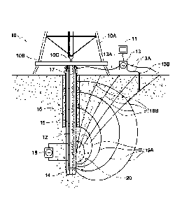
[0024] Figure 1 shows schematically an example drilling operation. A drill rig
10 drives a
drill string 12 which includes sections of drill pipe that extend to a drill
bit 14. The
illustrated drill rig 10 includes a derrick 10A, a rig floor 10B and draw
works 10C for
supporting the drill string. Drill bit 14 is larger in diameter than the drill
string above the
drill bit. An annular region 15 surrounding the drill string is typically
filled with drilling
fluid. The drilling fluid is pumped through a bore in the drill string to the
drill bit and
returns to the surface through annular region 15 carrying cuttings from the
drilling
operation. As the well is drilled, a casing 16 may be made in the well bore. A
blow out
preventer 17 is supported at a top end of the casing. The drill rig
illustrated in Figure 1 is
an example only. The methods and apparatus described herein are not specific
to any
particular type of drill rig.
[0025] A gap sub 20 may be positioned, for example, at the top of the BHA. Gap
sub 20
divides the drill string into two electrically-conductive parts that are
electrically insulated
from one another. The two parts form a dipole antenna structure. For example,
one part
of the dipole may be made of the BHA up to the electrically insulating gap and
the other
- 6 -
CA 02931556 2016-05-27
part of the dipole may be made up of the part of the drill string extending
from the gap to
the surface.
[0026] A very low frequency alternating current (AC) electrical signal 19A is
generated
by an EM telemetry signal generator 18 and applied across gap sub 20. The low
frequency
AC signal energizes the earth and creates an electrical field 19A which
results in a
measurable voltage differential between the top of drill string 12 and one or
more
grounded electrodes (such as ground rods or ground plates). Electrical signal
19A is
varied in a way which encodes information for transmission by telemetry.
[0027] At the surface the EM telemetry signal is detected. Communication
cables 13A
transmit the measurable voltage differential between the top of the drill
string and one or
more grounded electrodes 13B located about the drill site to a signal receiver
13. The
grounded electrodes 13B may be at any suitable locations. Signal receiver 13
decodes the
transmitted information. A display 11 displays some or all of the received
information.
For example, display 11 may display received measurement while drilling
information to
the rig operator.
[0028] Whether or not EM telemetry transmissions from a downhole source can be
reliably detected at the surface can depend on many factors. Some of these
factors have to
do with the characteristics of the underground formations through which the
well bore
from which the electromagnetic telemetry is being performed passes. The
electrical
conductivity of the underground environment can play a major role in the
effectiveness of
electromagnetic telemetry (higher electrical conductivity, especially in the
vicinity of gap
sub 20 tends to attenuate EM telemetry signals). Both the average electrical
conductivity
of the underground environment as well as the way in which the electrical
conductivity
may vary from place to place can play significant roles in whether particular
EM telemetry
signals can be received reliably at the surface.
[0029] Another factor that can affect electromagnetic telemetry is the depth
from which
electromagnetic telemetry is being performed. In general, electromagnetic
telemetry
signals become more highly attenuated as the depth from which the
electromagnetic
telemetry signals are being transmitted increases.
- 7 -
CA 02931556 2016-05-27
[0030] Another factor that may affect the success in receiving EM telemetry
transmissions
at the surface is the particular arrangement of signal detectors provided at
the surface (e.g.
the particular arrangement of grounding rods and other apparatus used at the
surface as
well as the sensitivity of the circuitry used to detect EM telemetry signals).
[0031] Other factors include: whether or not the wellbore is cased and, if so,
how deep the
casing extends; and the inclination of the portion of the drill bore in which
the EM
telemetry signal generator is located. It tends to be much more challenging to
achieve
effective EM telemetry transmission from a cased horizontal well bore than
from an
uncased vertical well bore.
[0032] Another factor that can affect the success of EM telemetry signal
transmissions is
the drilling activity that is occurring at the time of the transmissions. For
example, drilling
often has a number of phases. In one phase (which typically includes the time
at which a
new section of drill string is being added or taken off of the drill string)
the bore hole is
quiet. Drilling fluid is not being pumped through the drill string (i.e.
"pumps off"). At
other phases of the drilling operation drilling fluid is being pumped through
the drill
string. Active drilling may include different modes of operation. In some
modes of
operation the entire drill string is rotating as drilling progresses. In
another "sliding" mode
of operation the drill bit is rotated by a downhole mud motor and the drill
string is not
rotated except as is necessary or desirable to steer the direction in which
the drill bit is
progressing. Which of these modes is occurring can affect EM telemetry by
creating
electrical noise and the like.
[0033] Another factor that can affect the effectiveness of EM telemetry
transmissions is
whether and how much drilling fluid is used (e.g. underbalanced drilling may
use less
and/or less dense drilling fluids; in air-based underbalanced drilling the
wellbore may be
air-filled), the nature of drilling fluid being used (whether the drilling
fluid is oil-based or
water-based), and the specific characteristics of any drilling fluid being
used such as, for
example, the pressure, temperature, phase behaviour, electrical
conductivity/resistivity and
other fluid properties.
- 8 -
CA 02931556 2016-05-27
[0034] The combination of all the above factors creates a challenging
environment for
electromagnetic telemetry, especially where it is desired to optimize the
electromagnetic
telemetry to conserve electrical power and to maximize data throughput, where
desired.
[0035] In situations where EM telemetry is more difficult, for example because
of factors
such as one or more of the above (and most typically a combination of several
of the
above), one can adjust the nature of the EM telemetry signals to improve the
reliability of
the EM telemetry channel. The characteristics of EM telemetry signals
themselves can
affect their successful transmission to the surface. One characteristic that
has particular
significance is the frequency at which the EM telemetry signals alternate in
polarity and/or
magnitude.
[0036] In general, lower-frequency EM telemetry signals can be successfully
transmitted
from deeper locations than higher frequency EM telemetry signals. For this
reason, EM
telemetry signals typically have very low frequencies. For example, EM
telemetry signals
generally have frequencies in the band below 24 Hertz. For example, EM
telemetry
signals according to some embodiments of the invention have frequencies in the
range of
about 1/10 Hertz to about 20 Hertz. The exact endpoints of these ranges are
not critically
important.
[0037] One advantage of the use of higher frequencies for EM telemetry is that
the rate at
which data can be encoded in higher-frequency EM telemetry signals is greater
than the
rate at which the data can be encoded in lower-frequency EM telemetry signals.
Consequently, there is a trade-off between increasing the likelihood that EM
signals can
be successfully transmitted from a given depth by using very low frequencies
and
maintaining an increased data rate by using higher frequencies. Furthermore,
if the
frequency is too high then the EM signals will be so strongly attenuated that
no practical
detector could pick them up at the surface.
[0038] Selection of carrier frequency for EM telemetry signals can have
consequences
beyond the amount of time required to transmit a certain amount of data to the
surface.
For example, transmitting at higher frequencies may significantly affect the
amount of
electrical power required to transmit a certain amount of data. One reason for
this is that if
- 9 -
CA 02931556 2016-05-27
data can be transmitted quickly then, after the data has been transmitted (or
in other
periods during which it is not necessary to be transmitting data), certain
circuits may be
shut down to conserve electrical power. In addition, since the electrical
impedance seen
by an EM telemetry transmitter is somewhat frequency dependent, the amount of
electrical
power required to sustain an EM telemetry signal is also frequency dependent
to some
degree. On the other hand, higher frequencies are attenuated more strongly
than lower
frequencies and so higher frequency signals may need to be transmitted at
higher
amplitudes (thereby requiring more electrical power).
[0039] Another factor that influences the success of EM telemetry
transmissions is the
amplitude of the EM telemetry signals. Increased amplitude signals are easier
to detect at
the surface. However, the amplitude of EM telemetry signals may be limited by
the
capabilities of the downhole EM telemetry transmitter. For example, if the EM
telemetry
transmitting circuits can deliver only up to a maximum electrical current then
the
amplitude of the EM telemetry signal will also be limited.
[0040] Other limits are imposed by the maximum voltage that can be imposed by
the EM
telemetry transmitter on the downhole antenna elements. The voltage of an EM
telemetry
signal may be limited by the nature of the EM telemetry signal generator as
well as its
power source. In some cases the voltage may be limited by design to being
below a
threshold voltage for safety reasons. For example, in some embodiments, the
voltage may
be limited to a voltage of 50 volts or less in order to reduce the likelihood
that personnel
who are handling the EM telemetry signal generator at the surface could be
exposed to
electrical shocks and/or to reduce the likelihood that the EM signal generator
could serve
as an ignition source.
[0041] The voltage that may be applied across the EM telemetry antenna
elements may
also depend on the characteristics of the gap. Typically, for a longer gap, a
larger voltage
may be applied without exceeding the electrical current capabilities of the EM
telemetry
signal generator. In addition to the above, increasing the amplitude of EM
telemetry
signals generally results in increased electrical power consumption. It is
therefore
desirable not to transmit EM telemetry signals that have amplitudes much
greater than
necessary.
- 10 -
CA 02931556 2016-05-27
[0042] The encoding scheme used to transmit EM telemetry signals can also play
a role in
the success with which the EM telemetry signals can be received. For example,
if the
encoding scheme is such that it encodes information by, at least in part,
transmitting EM
telemetry signals of different amplitudes then it may be necessary for all of
the different
amplitudes which are part of the encoding scheme to be detectable at the
surface for the
EM telemetry transmission to be successfully received. If only some of the
amplitudes are
received at the surface it may not be possible to recover the transmitted
information at the
surface.
[0043] As another example, different encoding schemes may use different
numbers of
cycles to encode symbols for transmission. For example, in low-noise
environments one
may be able to successfully transmit EM telemetry symbols using an encoding
scheme
which transmits one symbol in two cycles of the EM telemetry signal. In higher
noise
environments it may be desirable or necessary to use an encoding scheme which
transmits
one symbol in three or more cycles of the EM telemetry signal.
[0044] One aspect of the present invention provides a system for optimizing EM
telemetry
by automatically selecting or assisting a user in the selection of appropriate
EM telemetry
parameters which may include one or more of: voltage, current, power, EM
telemetry
signal carrier frequency, EM telemetry signal amplitude, and EM telemetry
signal data
encoding scheme. In particular, appropriate EM telemetry parameters are set
based at
least in part on fluid analysis.
[0045] Various types of downhole drilling fluids may be employed in drilling
rig 10.
Each type of drilling fluid may have different characteristics. Possible types
of drilling
fluid employed in drilling rig 10 include, but are not limited to: water-based
fluids such as
non-dispersed systems, dispersed systems, saltwater drilling fluids, polymer
drilling fluids;
drill in fluids; oil-based fluids; synthetic-based drilling fluids; all-oil
fluids; and
pneumatic-drilling fluids such as air, mist, foam or gas. Drilling fluid may
be changed
during drilling. Drilling fluid may also contain additives such as lost-
circulation materials,
spotting fluids, lubricants and protective chemicals such as scale and
corrosion inhibitors,
biocides, and hydrogen sulfide scavengers.
-11-
CA 02931556 2016-05-27
[0046] Fluid analysis may involve evaluating one or more of: the composition
(or the
change in composition), phase behaviour, pressure, temperature, density,
volume,
electrical resistivity/conductivity, solids content (percentage by volume
and/or type of
solids) and/or other properties that determine a behaviour of the various
components of
drilling fluid.
[0047] In some embodiments, drilling rig 10 includes an apparatus 50 for
analyzing fluid.
Apparatus 50 may be located anywhere on drill string 12, where space permits.
For
example, apparatus 50 for analyzing fluid may be located in a downhole probe,
in a sub
such as a gap sub, near the drill bit, on the surface in a mud tank, pump
shack, draw works
or top drive or elsewhere. Apparatus 50 may be integrated into a pre-existing
downhole
element such as a downhole probe containing other sensors or may be a
standalone unit.
Apparatus 50 may comprise threaded couplings for attaching apparatus 50 inline
in drill
string 12. The threaded couplings may form part of the housing of apparatus
50.
,
[0048] Figure lA shows an example apparatus 50 having threaded couplings 50A
and 50B
at either end. In this embodiment, apparatus 50 is in the form of a gap sub
having an
electrically insulating gap 62 that electrically isolates uphole and downhole
ends of the
gap sub. An electromagnetic telemetry transmitter may be connected across gap
62.
[0049] Figure 1B shows another example apparatus 50 that is in the form of a
probe that
may be carried in a bore of a drill string.
[0050] In some embodiments, it is beneficial for apparatus 50 to be located
downhole.
Drilling fluids can include a combination of one or more of gaseous, liquid
and/or solid
phases, such as, water, oil, gas, flowable solid material etc. Drilling fluids
in downhole
conditions may exhibit different compositions, pressures and temperatures as
compared to
fluids at surface conditions. Electrical resistivity may also vary with depth
since electrical
resistivity can be dependent on temperature and pressure. As samples of
downhole fluids
are transported to the surface, the fluids are likely to change temperature
and exhibit other
changes in characteristics accordingly. Changes may include changes between
gaseous
and liquid phases and changes of compositional characteristics. Accordingly,
fluid
- 12-
CA 02931556 2016-05-27
analysis performed downhole is likely to provide more accurate results than
fluid analysis
done at the surface (whether or not the fluid came from downhole).
100511 Figure 2 depicts one embodiment of apparatus 50. Apparatus 50 may
comprise a
housing 52 containing one or more sensors (monitors, meters, etc.) 54. For
example,
apparatus 50 may comprise one or more of: an optical device 54a, such as a
spectrometer,
camera, imaging device, or the like, a temperature sensor 54b, a pressure
sensor 54c, a
flowmeter 54d, a fluid density sensor 54e, an electrical
conductivity/resistivity meter 54f,
a watercut meter (not shown), etc. Temperature sensor 54b, pressure sensor
54c,
flowmeter 54d, fluid density sensor 54e and electrical
conductivity/resistivity meter 54f
are all optional components of apparatus 50, as illustrated by the stippled
lines in Figure 2.
In some embodiments, one or more of: temperature sensor 54b, pressure sensor
54c,
flowmeter 54d, fluid density sensor 54e and electrical
conductivity/resistivity meter 54f
may be located in another part of drilling rig 10, may be part of another
downhole tool and
may communicate with apparatus 50 or a computing device connected to apparatus
50.
Apparatus 50 may also include a controller 56 for receiving data from the one
or more
sensors 54 and a transmitter 58 for transmitting data to the surface or to an
intermediate
transmitter or repeater.
100521 Housing 52 of apparatus 50 may be generally cylindrical in form such
that it can be
inserted and travel within drill string 12, although this is not mandatory.
Housing 52 may
have one or more openings or optical accesses for allowing sensors 54 to
adequately
perform their functions. For example, optical access 60 may be provided in
housing 52
such that optical device 54a has optical access to the drilling fluid. Other
optical accesses
60 may be provided for other sensors 54 as needed.
[00531 Housing 52 may be made from a range of materials including metals and
plastics
suitable for exposure to downhole conditions. Some non-limiting examples are
suitable
thermoplastics, elastomeric polymers, rubber, copper or copper alloy, alloy
steel, and
aluminum. For example housing 52 may be made from a suitable grade of PEEK
(Polyetheretherketone), PET (Polyethylene terephthalate) or PPS (Polyphenylene
sulfide)
plastic. Where housing 52 is made of plastic, the plastic may be fiber-filled
(e.g. with
glass fibers) for enhanced erosion resistance, structural stability and
strength. The
- 13 -
CA 02931556 2016-05-27
material of housing 52 should be capable of withstanding downhole conditions
without
degradation. The ideal material can withstand temperatures of up to at least
150C
(preferably 175C or 200C or more), is chemically resistant or inert to any
drilling fluid to
which it will be exposed, does not absorb fluid to any significant degree and
resists
erosion by drilling fluid. The material characteristics of housing 52 may be
uniform, but
this is not necessary.
[0054] Optical device 54a may sense light that has contacted the drilling
fluid and rely on
characterizing the sensed light to perform analysis of the fluid. In some
embodiments,
optical device 54a may physically sample the drilling fluid while in other
embodiments,
optical device may view the drilling fluid through optical access 60. Optical
device 54a
may comprise one or more light sources for illuminating the drilling fluid,
one or more
photo detectors that sense light that has contacted the drilling fluid in
order to determine
sensed data and processing elements that process the sensed data to determine
fluid
characteristics. Optical device 54a may use reflection-type lighting,
fluorescent lighting, a
light focussing device, light emitting diodes (LEDs) etc. for obtaining
optimal lighting
conditions.
[0055] In some embodiments, optical device 54a comprises a spectrometer. In
particular,
optical device 54a may comprise a near-infrared spectrometer (i.e. a
spectrometer that uses
the near-infrared region of the electromagnetic spectrum, from about 800nm to
about
2500nm).
[0056] In some embodiments, housing 52 includes one or more optical accesses
60 such
that optical device 54a can provide and receive light to and from the drilling
fluid. In
some embodiments, optical access 60 may have a protective covering to protect
the
contents of housing 52. The protective covering should be strong and allow
visible light
and near-infrared light to pass through. In some embodiments, the protective
covering is
made of glass or a polymer such as polycarbonate.
[0057] Optical access 60 may be located to optically analyze drilling fluid
outside of a
drill string or within a bore of the drill string. Figure lA shows an example
embodiment
in which optical access 60 is on an outside of a housing 52. Also shown in
Figure lA are
- 14 -
CA 02931556 2016-05-27
electrodes 61 which may be used for resistivity measurements by electrical
conductivity/resistivity meter 54f.
[0058] The embodiment of Figure 1B includes an optical access 60 which is
located to
permit drilling fluid flowing within a bore of a drill string to be analyzed.
Also shown in
Figure 1B are contacts 61 for measuring resistivity of drilling fluid. An
electromagnetic
telemetry transmitter/receiver may be connected across electrically insulating
gap 62 in
housing 52.
[0059] Temperature sensor 54b may comprise any suitable temperature sensing
device.
For example, temperature sensor 54b may comprise an infrared thermometer, a
thermocouple, a thermistor, resistance thermometers, etc. Temperature sensor
54b may be
connected to controller 56.
[0060] Pressure sensor 54c may comprise any suitable pressure measuring
device. For
example, pressure sensor 54c may comprise a pressure transducer, a diaphragm
gauge, a
bellows gauge, a Bourdon gauge, etc. Pressure sensor 54c may be connected to
controller
56. In some embodiments, since a number of pressure sensors may already be
located
downhole, pressure measurements from another sensor are transmitted to
apparatus 50 or
another sensor used in conjunction with apparatus 50.
[0061] Various types of commercially available fluid meters exist and are
suitable for use
as flowmeter 54d. In one particular embodiment, flow meter 54d is a turbine
flow meter.
Other types of flow meters that could be used include, but are not limited to,
mechanical
flow meters such as piston meters, oval gear meters, helical gear meters,
nutating disk
meters, variable area meters, Woltmann meters, single jet meters, and multiple
jet meters;
pressure-based meters such as venturi meters, orifice plates, dall tubes,
pilot tubes, and
cone meters; and optical flow meters. Flowmeter 54d may be connected to
controller 56.
[0062] Fluid density sensor 54e may comprise any suitable fluid density
sensing device.
For example, fluid density sensor 54e may comprise a Coriolis meter, an
ultrasonic density
meter, a nuclear density gauge etc. Fluid density sensor 54e may be connected
to
controller 56.
- 15-
CA 02931556 2016-05-27
[0063] Electrical conductivity/resistivity meter 54f may comprise any suitable
electrical
conductivity/resistivity measuring device. Since electrical conductivity of a
solution (e.g.
a drilling fluid) is highly temperature dependent, it is beneficial to either
use a temperature
compensated electrical conductivity/resistivity measuring device or to
calibrate the
measuring device at the same temperature as the solution being measured. In
some
embodiments, temperature sensor 54b and electrical conductivity/resistivity
meter 54f are
used together to obtain accurate temperature-compensated measurements. The
electrical
conductivity/resistivity meter 54f may be an electrode contacting type (with
two or four
electrodes) or an inductive type. In some embodiments, electrical
conductivity/resistivity
is measured across an electrically insulating gap also used for
electromagnetic telemetry
transmission and/or reception. In some embodiments, where electrical
conductivity/resistivity meter 54f is not present, electrical resistivity may
be approximated
based on drilling fluid type. Drilling fluid type may be determined by
comparing a
spectrum obtained by optical device 54a to spectrums of known drilling fluid
types. One
or more of pressure and temperature readings may be used to calibrate the
electrical
resistivity reading approximation.
[0064] In some embodiments, the annulus fluid may be monitored for cuttings
from
formations. Such cuttings may indicate what type of formation is being drilled
through.
[0065] Each sensor 54 may be configured to take continuous measurements,
periodic
measurements or measurements on command. Each sensor 54 may be configured to
send
all measurements to controller 56 or only measurements that exhibit a change.
The change
may be compared to a threshold change value or proportion such that only
changes above
the threshold level are sent to controller 56. The threshold may be set by an
operator and
may be adjusted as needed.
[0066] Transmitter 58 may comprise one or more of a number of suitable data
transmission systems. In some embodiments, transmitter 58 is an EM telemetry
transmitter that sends data directly to the surface. In other embodiments,
transmitter 58
may send data to an EM telemetry repeater which in turn sends the data to
another repeater
or the surface. In other embodiments still, transmitter 58 may be any wired or
wireless
connection between apparatus 50 and an EM telemetry system.
- 16 -
CA 02931556 2016-05-27
[0067] Controller 56 (and components thereof) may comprise hardware, software,
firmware or any combination thereof. For example, controller 56 may be
implemented on
a programmed computer system comprising one or more processors, user input
apparatus,
displays and/or the like. Controller 56 may be implemented as an embedded
system with
a suitable user interface comprising one or more processors, user input
apparatus, displays
and/or the like. Processors may comprise microprocessors, digital signal
processors,
graphics processors, field programmable gate arrays, and/or the like.
Components of
controller 56 may be combined or subdivided, and components of the controller
may
comprise sub-components shared with other components of the controller.
Components of
controller 56, may be physically remote from one another.
[0068] In some embodiments, apparatus 50 is configured to measure fluid
characteristics
using sensors 54, which transmit the measurements to controller 56. Controller
56 may
then determine a set of optimal transmission settings 74 to be sent to the EM
telemetry
system or may cause the measurements to be transmitted to the surface via
transmitter 58
and an appropriate telemetry system.
[0069] In a particular embodiment, apparatus 50 comprises a near-infrared
spectrometer
54a, controller 56 and transmitter 58. Controller 56 may be configured to
direct near-
infrared spectrometer 54a to take a measurement of the drilling fluid.
Infrared
spectrometer 54a outputs a spectrum to controller 56. Controller 56 is
configured to
compare the measured spectrum to known spectrums of different types of
drilling fluids
(e.g. water-based fluids such as non-dispersed systems, dispersed systems,
saltwater
drilling fluids, polymer drilling fluids; drill in fluids; oil-based fluids;
synthetic-based
drilling fluids; all-oil fluids; and pneumatic-drilling fluids such as air,
mist, foam or gas).
Controller 56 may be configured to accommodate for the addition of one or more
additives
(e.g. spotting fluids, lubricants and protective chemicals such as scale and
corrosion
inhibitors, biocides, and hydrogen sulfide scavengers).
[0070] After matching the measured spectrum to a known spectrum of a drilling
fluid
type, transmission settings module 70 (which may be part of controller 56 or
may be part
of a surface computing device) determines optimal transmission settings 74.
Each type of
drilling fluid may be associated with a set of pre-determined optimal
transmission settings
- 17-
CA 02931556 2016-05-27
74. Optimal transmission settings 74 may comprise a settings profile that
provides exact
values depending on further variables such as depth, pressure or temperature
of the drilling
fluid. Optimal transmission settings 74 may also be based solely on the
drilling fluid type
or may be based on one or more of at least: transmission settings module 70
may receive
one or more of: depth data 72b, signal detector layout data 72c, drilling
casing data 72d,
drilling activity data 72e, underground formations data 72f, electrical power
data 72g, pre-
existing transmission limitations 72h, historical transmission settings 72j,
feedback from
the surface 72k and transmission priority data 721.
[0071] After determining optimal transmission settings 74, transmitter 58 may
be
configured to transmit optimal transmission settings 74 either to the surface
to be
accepted, altered or rejected by an operator, or directly to one or more
transmitter/receivers that are part of the EM telemetry system. The EM
telemetry system
can uplink/downlink optimal transmission settings 74 so that each
transmitter/receiver
operates at the new optimal transmission settings 74. Apparatus 50 may be
configured to
take another measurement and start the process again.
[0072] In another particular embodiment, apparatus 50 comprises a near-
infrared
spectrometer 54a, temperature sensor 54b, electrical conductivity meter 54f,
controller 56
and transmitter 58. Controller 56 may be configured to direct near-infrared
spectrometer
54a to take a measurement of the drilling fluid. Infrared spectrometer 54a
outputs a
spectrum to controller 56. Apparatus 50, of this particular embodiment, is
configured to
operate in a substantially similar way as other embodiments of apparatus 50
except with
the additional input of electrical resistivity and temperature of the drilling
fluid for
determining optimal transmission settings 74.
[0073] Another aspect of the invention provides a method for optimizing EM
telemetry by
automatically selecting or assisting a user in the selection of appropriate EM
telemetry
parameters which may include one or more of: voltage, current, power, EM
telemetry
signal carrier frequency, EM telemetry signal amplitude, and EM telemetry
signal data
encoding scheme. In particular, appropriate EM telemetry parameters may be
optimized
based on results of fluid analysis by sensors 54.
- 18-
CA 02931556 2016-05-27
[0074] Figure 3 provides a flowchart illustrating an exemplary method 100 for
optimizing
EM telemetry by selecting or assisting a user in the selection of appropriate
EM telemetry
parameters. In some embodiments, an operator may need to start the system
while in other
embodiments, the system is continuously in operation, continuously in
operation while
downhole or continuously in operation while drilling rig 10 is in operation.
[0075] In block 102, one or more fluid characteristics are measured. In some
embodiments, resistivity/conductivity is measured (in some embodiments, for
example,
resistivity/conductivity may be inferred from composition). In some
embodiments, the one
or more fluid characteristics measured in block 102 comprise one or more of at
least
composition, phase behaviour, pressure, temperature, volume, density,
electrical
conductivity/resistivity etc. The one or more fluid characteristics measured
may be
measured at one particular location along drill string 12 or at several
locations along drill
string 12. The one or more fluid characteristics may all be measured at the
same time, in
sequence, periodically or continuously. In some embodiments, a number of
measurements
are taken and averaged. In some embodiments, measurements may be taken when
the
transmitter is within a formation being drilled through.
[0076] In block 104, the measured fluid characteristics are sent to controller
56. Measured
fluid characteristics may be sent to controller 56 continuously or
periodically. Controller
56 may include data storage 56a for storing measured fluid characteristics.
Controller 56
may keep track of fluid characteristics and monitor fluid characteristics for
any changes
above a threshold value. Accordingly, in some embodiments, controller 56 may
only
transmit fluid characteristics that exhibit a change over a threshold value or
proportion. In
block 106, whether or not a threshold level of change has occurred in a
measured fluid
characteristic is determined. If the threshold level is met, the process goes
to block 108 or
block 118, depending on where the determination of optimal transmission
settings 74 is
performed.
[0077] The location(s) where transmission settings 74 are determined may vary
in
different embodiments. As shown in Figure 3, after determining whether or not
there is a
change in a measured fluid characteristic above a threshold level, in block
106, the process
may go to either of block 108 or block 118. If transmission settings module 70
is part of
- 19 -
CA 02931556 2016-05-27
controller 52 of the downhole EM telemetry system or is located somewhere
downhole
such as in part of the BHA, the process goes to block 108. If transmission
settings module
70 is located at the surface as part of a computer system located at the
surface, the process
goes to block 118. In block 118, the fluid characteristic(s) are transmitted
to the surface
before going to block 120 where the optimal transmission settings are
determined.
[0078] Block 108 and block 120 are similar, although they occur in different
locations. In
each of block 108 and block 120, optimal transmission settings 74 based on
fluid
characteristics are determined. Figure 4 provides a schematic block diagram
illustrating
one embodiment of block 108 or block 120.
[0079] In Figure 4, transmission settings module 70 receives one or more
separate inputs.
Each input is a different factor 72. It should be understood that inputting
some of the
factors 72 is optional (as is illustrated by the stippled lines between some
of the factors 72
and transmission settings module 70). Using one or more factors 72,
transmission settings
module 70 determines a set of optimal transmission settings 74 for the EM
telemetry
system.
[0080] In determining optimal transmission settings 74, different factors can
be given
different weights depending on the objectives. In some embodiments, an
objective is to
obtain the best signal quality at the surface. In other embodiments, an
objective may be to
minimize energy usage while maintaining sufficient signal quality. In other
embodiments,
higher data throughput may be an objective. In other embodiments, the
objective may be a
combination of at least maximizing data throughput, conserving energy and
obtaining the
best signal quality at the surface.
[0081] Optimal transmission settings 74 may comprise a set of operating
parameters for
the EM telemetry system. The operating parameters may include one or more of
voltage,
current, power, EM telemetry signal carrier frequency, EM telemetry signal
amplitude,
and EM telemetry signal data encoding scheme. Optimal transmission settings 74
may
comprise a range of values or exact values. Optimal transmission settings 74
may
comprise a settings profile that provides settings values which depend on one
or more of
temperature, pressure and depth.
- 20 -
CA 02931556 2016-05-27
[0082] In some embodiments, transmission settings module 70 receives only
fluid data
characteristics as input for determining optimal transmission settings 74. As
detailed
above, fluid characteristics 72a may include one or more of at least
composition, phase
behaviour, pressure, temperature, volume, density, electrical
conductivity/resistivity etc.
Based on the one or more fluid characteristics 72a, transmission settings
module 70 may
determine optimal transmission settings 74 at which the EM telemetry system
should
operate.
[0083] In some embodiments, transmission settings module 70 comprises an
algorithm, a
lookup table or a function that provides transmission settings based on all of
the available
factors 72. In other embodiments, transmission settings module 70 comprises a
plurality
of algorithms, lookup tables or functions, one lookup table or function for
each available
factor 72, and transmission settings module 70 must balance and optimize the
transmission
settings based on the plurality of algorithms, lookup tables or functions to
obtain the
optimal transmission settings 74. In some embodiments, the lookup tables
and/or
functions are based on historical data while in other embodiments they are
based on
theoretical data. The algorithm(s), lookup table(s) and/or functions may be
updated
periodically based on actual results. Updates may be downlinked via an
available
telemetry system, may be determined downhole or may be applied when apparatus
50 is
brought to the surface.
[0084] In some embodiments, based on the composition of the drilling fluid as
measured
by optical device 54a, transmission settings module 70 may determine that one
or more
transmission settings should be altered to obtain optimal transmission
settings 74.
[0085] In some embodiments, optical device 54a may comprise a near-infrared
spectrometer. The near-infrared spectrometer produces a spectrum corresponding
to the
drilling fluid for interpretation by transmission settings module 70.
Transmission settings
module may compare the measured spectrum to spectrums of known types of
drilling fluid
(e.g. water-based fluids such as non-dispersed systems, dispersed systems,
saltwater
drilling fluids, polymer drilling fluids; drill in fluids; oil-based fluids;
synthetic-based
drilling fluids; all-oil fluids; and pneumatic-drilling fluids such as air,
mist, foam or gas) to
find a closest match. In some embodiments, transmission settings module 70 is
configured
-21-
CA 02931556 2016-05-27
to accommodate additives within the drilling fluid that may affect the
measured spectrum.
In embodiments where optimal transmission settings 74 are determined at the
surface, it
may be beneficial to determine the drilling fluid type downhole (e.g.
controller 56 may be
configured to determine the drilling fluid type) in order to minimize the data
that is
transmitted to the surface.
[0086] After determining which type of drilling fluid is the closest match,
transmission
settings module 70 may determine a set of optimal transmission settings. For
example, the
transmission settings module 70 may determine that the power settings should
be altered.
In particular, lower power may be preferred in oil based drilling fluid while
higher power
may preferred in water/brine based drilling fluids. In other embodiments, one
or more of
the voltage, current, power, EM telemetry signal carrier frequency, EM
telemetry signal
amplitude, and EM telemetry signal data encoding scheme may also be altered
based on
the composition of the drilling fluid. Through use of the invention disclosed
herein, further
relationships may be discovered and known relationships may be refined.
[0087] In other embodiments, the measured spectrum may not provide a close
match to
any known drilling fluid, or any known combination of drilling fluid and
additives. In
such embodiments, apparatus 50 may be configured to run a signal sweep in
order to
determine optimal transmission settings 74. A signal sweep may comprise a
plurality of
signals at different frequencies. This method determines whether each of the
sweep
signals is received at the uphole system and for each sweep signal received,
measures
parameters of the received sweep signal. The parameters comprise at least one
of signal
strength and signal-to-noise ratio. Based at least in part on the sweep
signals received and
the parameters measured, the method determines a set of optimal transmission
settings 74
for the unknown drilling fluid type. This set of optimal transmission settings
74 for the
unknown drilling fluid type may be saved with the corresponding spectrum by
transmission settings module 70 for future use.
[0088] In some embodiments, based on the temperature of the drilling fluid as
measured
by temperature sensor 54b, transmission settings module 70 may determine that
one or
more transmission settings should be altered to obtain optimal transmission
settings 74.
For example, the transmission settings module 70 may determine that the
voltage and
- 22 -
CA 02931556 2016-05-27
current should be altered. In water-based drilling fluids, the electrical
resistivity of water
decreases as the temperature increases. Higher temperatures therefore allow
for higher
maximum current draws. Accordingly, higher voltage and lower current may be
preferred
in lower temperature water-based drilling fluid while lower voltage and higher
current .
may be preferred in higher temperature water-based drilling fluids. In other
embodiments,
one or more of voltage, current, power, EM telemetry signal carrier frequency,
EM
telemetry signal amplitude, and EM telemetry signal data encoding scheme may
also be
altered based on the temperature of the drilling fluid.
[0089] In some embodiments, based on the pressure of the drilling fluid as
measured by
pressure sensor 54c, transmission settings module 70 may determine that one or
more
transmission settings should be altered to obtain optimal transmission
settings 74. For
example, the transmission settings module 70 may determine that the voltage
and current
should be altered. In water-based drilling fluids, the electrical resistivity
of water
decreases as the pressure increases. Accordingly, higher voltage and lower
current may be
preferred in lower pressure water-based drilling fluid while lower voltage and
higher
current may be preferred in higher pressure water-based drilling fluids. In
other
embodiments, one or more of the voltage, current, power, EM telemetry signal
carrier
frequency, EM telemetry signal amplitude, and EM telemetry signal data
encoding scheme
may also be altered based on the pressure of the drilling fluid.
[0090] In some embodiments, based on the flow rate of drilling fluid as
measured by
flowmeter 54d, transmission settings module 70 may determine that one or more
transmission settings should be altered to obtain optimal transmission
settings 74. For
example, the transmission settings module 70 may determine that one or more of
the
voltage, current, power, EM telemetry signal carrier frequency, EM telemetry
signal
amplitude, and EM telemetry signal data encoding scheme should be altered
based on the
flow rates of drilling fluid.
[0091] In some embodiments, based on the density of the drilling fluid as
measured by
density sensor 54e, transmission settings module 70 may determine that one or
more
transmission settings should be altered to obtain optimal transmission
settings 74. For
example, the transmission settings module 70 may determine one or more of the
voltage,
- 23 -
CA 02931556 2016-05-27
current, power, EM telemetry signal carrier frequency, EM telemetry signal
amplitude,
and EM telemetry signal data encoding scheme should be altered based on the
density of
the drilling fluid.
[0092] In some embodiments, based on the electrical resistivity of the
drilling fluid as
measured by electrical conductivity/resistivity meter 54f, transmission
settings module 70
may determine that one or more transmission settings should be altered to
obtain optimal
transmission settings 74. The electrical resistivity may change due to
changing fluid
composition, temperature, pressure, or other fluid characteristics. In
general, the voltage
should increase with increasing electrical resistivity and the current should
decrease with
increasing resistivity. Conversely, the voltage should decrease with
decreasing electrical
resistivity and the current should increase with decreasing electrical
resistivity. In other
embodiments, one or more of the voltage, current, power, EM telemetry signal
carrier
frequency, EM telemetry signal amplitude, and EM telemetry signal data
encoding scheme
may also be altered based on the pressure of the drilling fluid.
[0093] In other embodiments, in addition to fluid characteristics data 72a,
transmission
settings module 70 may receive one or more of: depth data 72b, signal detector
layout data
72c, drilling casing data 72d, drilling activity data 72e, underground
formations data 72f,
electrical power data 72g, pre-existing transmission limitations 72h,
historical
transmission settings 72j, feedback from the surface 72k and transmission
priority data
721. In some embodiments, transmission settings module 70 may receive
additional data
relating to additional factors.
[0094] Depth data 72b may, for example, relate to the depth at which the EM
telemetry
signal is being generated. At greater depths, greater attenuation is typically
expected.
Signal detector layout data 72c may relate to the arrangement of grounded
electrodes 13B.
Drilling casing data 72d may, for example, relate to whether or not there is a
casing 16,
how long casing 16 extends, the inclination of casing 16 and the inclination
of the
wellbore at the location of the EM telemetry signal generator. Drilling
activity data 72e
may, for example, relate to the current drilling mode such as whether or not
there is a
pump off condition and, if not, whether drilling is being performed in a
sliding mode or in
a rotating mode at which the entire drill string is being rotated. Underground
formations
- 24 -
CA 02931556 2016-05-27
data 72f may, for example, relate to the electrical conductivity of the
underground
environment on average or from place to place. Electrical power data 72g may,
for
example, relate to limits imposed by a desire to conserve electrical power
and/or available
reserves or electrical power. Pre-existing transmission limitations 72h may,
for example,
relate to a set of one or more transmission settings at which signals can be
received at the
surface under current operating conditions and any limitations of the
telemetry hardware
as discussed above. Historical transmission settings 72i may, for example,
relate to the
current transmission settings or data obtained from previous environments and
transmission settings. Feedback from surface 72j may, for example, relate to
feedback
received based on the signals obtained by grounded electrodes 13B and signal
receivers
13. Transmission priority data 72k may, for example, relate to a desired rate
for certain
data. For example, it may be desired to transmit "tool face" information ¨
information
specifying the current orientation of a drill bit ¨ using a high data rate
such that the
information may be received at the surface with low latency.
[0095] In some embodiments, transmission settings module 70 receives feedback
72j from
one or more grounded electrodes 13B and signal receivers 13 provided at the
surface. The
one or more grounded electrodes 13B and signal receivers 13 at the surface may
measure
signal attenuation and signal noise. Using feedback 72j, transmission settings
module 70
may determine new transmission settings and/or may adjust the one or more
lookup tables
or functions for future use.
[0096] After determining optimal transmission settings 74 in block 108,
optimal
transmission settings 74 may be sent to the surface. At this point, the method
moves to
block 112 for one of block 120 and block 110. In block 112, an opportunity for
user input
is provided. In block 112, an operator may choose to accept, alter or reject
optimal
transmission settings 74. Block 112, which allows for user input is optional.
In some
embodiments, it is preferable to have no user input and for the EM telemetry
system to run
efficiently with little or no user input. After accepting or altering optimal
transmission
settings 74, optimal transmission settings 74 are sent (or downlinked) to some
or all of the
appropriate transmitters, receivers and repeaters that are part of the EM
telemetry system.
- 25 -
CA 02931556 2016-05-27
[0097] The downlink transmission may be by EM telemetry but may also or
instead be
transmitted using another telemetry type. Example alternative telemetry types
that may be
used for the downlink telemetry include: mud pulse telemetry, drill string
acoustic
telemetry, telemetry performed by operating the drilling equipment e.g. by
rotating the
drill string and/or turning on or off the flow of drilling fluid or regulating
the flow of
drilling fluid in a pattern detectable by sensors at the downhole EM telemetry
signal
generator.
[0098] Alternatively, in other embodiments, after optimal transmission
settings 74 are
determined in block 108, the optimal transmission settings 74 may be sent to
the BHA, as
in block 122, before being transmitted to all appropriate transmitters,
receivers and
repeaters of the EM telemetry system, as in block 124.
[0099] After optimal transmission settings 74 are transmitted to all
appropriate
transmitters, receivers and repeaters of the EM telemetry system (either in
block 116 or
block 124), the EM telemetry system operates at the new optimal transmission
settings 74,
as in block 116, until the process begins again at block 102. The entire
process may
operate continuously, periodically, according to a schedule or at the command
of an
operator.
[0100] Downhole apparatus 50 and the EM telemetry system may be powered by one
or
more types of batteries located downhole. In some embodiments, to adjust
voltage and
current, different battery configurations may be employed. For example, to
obtain high
voltage and maintain the current, batteries may be connected in series whereas
to obtain
high current and maintain the voltage, batteries may be connected in parallel.
[0101] In other embodiments, characteristics of the drilling fluid may be such
that the EM
telemetry system should be shut down. In some embodiments, a backup form of
telemetry
may then be employed, such as mud pulse telemetry. In particular, in
situations where the
electrical resistivity of the drilling fluid is too high and too much power
would be required
to transmit EM telemetry signals, it may be beneficial to shut off the EM
telemetry system
to save power. Conversely, it may be beneficial to shut off the EM telemetry
system for
safety reasons when electrical resistivity of the drilling fluid is too low.
- 26 -
CA 02931556 2016-05-27
[0102] Another aspect of the invention provides a drill rig 10 having multiple
apparatuses
50 spaced apart along drill sting 12. Each apparatus along drill sting 12 may
measure fluid
characteristics at its spaced apart location along drill sting 12.
Transmission settings for
EM transmitters may be adjusted according to the fluid characteristics as
measured by the
nearest apparatus 50. Accordingly, EM transmitters along drill string 12 may
operate
using different transmission settings in order to minimize attenuation and
noise.
[0103] Embodiments of the invention may employ any suitable scheme for
encoding data
in an EM telemetry signal. One such scheme is QPSK (quadrature phase shift
keying).
Another scheme is BPSK (binary phase shift keying). A PSK (phase-shift keying)
encoding scheme may use a number of cycles (at the current frequency) to
transmit each
symbol. The number of cycles used to transmit each symbol may be varied. For
example,
in low-noise environments one may be able to successfully transmit EM
telemetry
symbols using two cycles per symbol. In higher noise environments it may be
desirable or
necessary to use three cycles (or more) to transmit each symbol. In some
embodiments
the number of cycles to be used to encode a symbol is selected based on a
measured
signal-to-noise ratio (SNR) in a recent sweep. Other encoding schemes include
FSK
(frequency-shift keying), QAM (quadrature amplitude modulation), 8ASK (8
amplitude
shift keying), APSK (amplitude phase shift keying) etc. Schemes which use any
suitable
combinations of changes in phase, amplitude, timing of pulses and/or frequency
to
communicate data may be applied.
[0104] Some embodiments make use of other modes of telemetry in addition to EM
telemetry. For example, mud pulse telemetry may be used to transmit downlink
signals
and/or to transmit uplink signals. This capability may be used to allow
communication to
or from the downhole EM telemetry system to be made reliably and yet provide
at least
one mode of communication which has a relatively low latency to achieve rapid
response
of the downhole EM telemetry system. For example, rapid changes in the
behaviour of the
downhole EM telemetry system, e.g. switching between configuration files,
could be
achieved very quickly using fast EM downlink telemetry. Data that is less time
sensitive
to be transmitted to the EM telemetry system may be transmitted by a slower,
but possibly
more reliable in all circumstances, mode of data transmission. Transmission by
different
-27-
CA 02931556 2016-05-27
modes may occur simultaneously (concurrently) or overlapping in time or may be
done at
different times.
[0105] While a number of exemplary aspects and embodiments have been discussed
above, those of skill in the art will recognize certain modifications,
permutations, additions
and sub-combinations thereof. It is therefore intended that the following
appended claims
and claims hereafter introduced are interpreted to include all such
modifications,
permutations, additions and sub-combinations as are within their true spirit
and scope.
Interpretation of Terms
[0106] Unless the context clearly requires otherwise, throughout the
description and the
claims:
= "comprise", "comprising", and the like are to be construed in an
inclusive sense, as
opposed to an exclusive or exhaustive sense; that is to say, in the sense of
"including, but not limited to".
= "connected", "coupled", or any variant thereof, means any connection or
coupling,
either direct or indirect, between two or more elements; the coupling or
connection
between the elements can be physical, logical, or a combination thereof
= "herein", "above", "below", and words of similar import, when used to
describe
this specification shall refer to this specification as a whole and not to any
particular portions of this specification.
= "or", in reference to a list of two or more items, covers all of the
following
interpretations of the word: any of the items in the list, all of the items in
the list,
and any combination of the items in the list.
= the singular forms "a", "an", and "the" also include the meaning of any
appropriate
plural forms.
[0107] Words that indicate directions such as "vertical", "transverse",
"horizontal",
"upward", "downward", "forward", "backward", "inward", "outward", "vertical",
"transverse", "left", "right", "front", "back"," "top", "bottom", "below",
"above", "under",
and the like, used in this description and any accompanying claims (where
present) depend
on the specific orientation of the apparatus described and illustrated. The
subject matter
- 28 -
CA 02931556 2016-05-27
described herein may assume various alternative orientations. Accordingly,
these
directional terms are not strictly defined and should not be interpreted
narrowly.
[0108] Where a component (e.g. a circuit, module, assembly, device, drill
string
component, drill rig system, etc.) is referred to above, unless otherwise
indicated,
reference to that component (including a reference to a "means") should be
interpreted as
including as equivalents of that component any component which performs the
function of
the described component (i.e., that is functionally equivalent), including
components
which are not structurally equivalent to the disclosed structure which
performs the
function in the illustrated exemplary embodiments of the invention.
[0109] Specific examples of systems, methods and apparatus have been described
herein
for purposes of illustration. These are only examples. The technology provided
herein
can be applied to systems other than the example systems described above. Many
alterations, modifications, additions, omissions and permutations are possible
within the
practice of this invention. This invention includes variations on described
embodiments
that would be apparent to the skilled addressee, including variations obtained
by: replacing
features, elements and/or acts with equivalent features, elements and/or acts;
mixing and
matching of features, elements and/or acts from different embodiments;
combining
features, elements and/or acts from embodiments as described herein with
features,
elements and/or acts of other technology; and/or omitting combining features,
elements
and/or acts from described embodiments.
[0110] It is therefore intended that the following appended claims and claims
hereafter
introduced are interpreted to include all such modifications, permutations,
additions,
omissions and sub-combinations as may reasonably be inferred. The scope of the
claims
should not be limited by the preferred embodiments set forth in the examples,
but should
be given the broadest interpretation consistent with the description as a
whole.
- 29 -