Note: Descriptions are shown in the official language in which they were submitted.
CA 02931865 2016-06-02
Cornerite Device for Suitcase and Suitcase
Technical Field
The present application relates to the field of cases and bags, and
particularly to a cornerite device for a suitcase and a suitcase.
Background Art
At present, with the rapid pace of social life and the progress of economy,
science, and technology, people travel more frequently. Tourisms, vacation
aboard, business trips, friend visiting, off-site learning, home-returning and
so
on are very common. As more travels are needed, suitcases for storing goods
become essential items for people..
People expect the suitcase to have not only a large carrying capacity,
ruggedness and durability, but also an aesthetic appearance. In the prior art,
depending on different carrying capacities, suitcases of different sizes are
available in the market for consumers to choose; moreover, the suitcases may
be in various colors and appearances, in terms of aesthetics.
The ruggedness and durability are mainly reflected in aspects, such as a
case body of the suitcase being difficult to be deformed, wearable and
difficult
to be damaged. At present, in addition to wheels, regions of the suitcase,
where wearing occurs firstly, are eight corners respectively located at a top
surface and a bottom surface of the case body. Each corner is a region where
three surfaces of the case body are connected. When placing suitcases at a
corner, under beds, into cabinets, in carriages, onto shelves of trains or
into
cargo storages of planes, it would be such corners which are subjected to
wear,
or in other words, severely worn out.
It is found by the inventor in his/her research that some of suitcases in the
prior art are designed to have cornerite for the case body by covering a layer
of
wear-resistant material on individual corners of the case body. However, this
design only enables the corners to be protected from being worn out, but
incapable of improving the compression resistance of the case body.
Prior suitcases achieve the anti-deformation ability mainly by means of an
outline frame or a supporting frame of the case body, since the case body
would be easily broken if designed to be made from hard plastic, or the cost
would be high and the weight is difficult to be controlled if designed to be
made
from metal.
Disclosure of the Invention
An object of the present application is to provide a cornerite device for a
suitcase and a suitcase, to improve the above-mentioned problems.
CA 02931865 2016-06-02
The present application is achieved as follows.
A cornerite device for a suitcase, comprising at least one first cornerite
configured to wrap a top corner of a case body of a suitcase and at least one
second cornerite configured to wrap a bottom corner of the case body, with a
side edge of the first cornerite and/or a side edge of the second cornerite
abutting against respective opening-closing frames of the suitcase.
The cornerite device includes two types of cornerites, i.e., the first
cornerite
wrapping the top corner and the second cornerite wrapping the bottom corner,
to protect the corners of the case body from being worn out. The difference
between the first cornerite and the second cornerite lies in that a fixation
mode
of wheels provided at the bottom of the case body needs to be considered for
the bottom corner, so they have different structures. Since the side edges of
the first cornerites and the second cornerites abut against the opening-
closing
frames of the suitcase, counterforces applied by the first cornerites and the
second cornerites must be overcome when the case body of the suitcase
tends to deform, thereby improving the compression resistance of the case
body to make the suitcase rugged and durable.
Further, the first cornerite comprises a first cornerite plate, a second
cornerite plate and a third cornerite plate perpendicular to each other, the
first
cornerite plate, the second cornerite plate and the third cornerite plate are
used to fit with three surfaces forming the top corner of the case body
respectively, and one end of the first cornerite plate away from the second
cornerite plate abuts against the opening-closing frame of the suitcase.
The first cornerite wraps a part of regions of the three surfaces of the case
body on the basis of the corner, and has one side edge abutting against the
opening-closing frame of the suitcase, thereby increasing wrapped area, and
improving the compression resistance of the case body.
Further, any two of the first cornerite plate, the second cornerite plate and
the third cornerite plate are connected with each other via an arc wall, and
integrally formed.
Any two of the individual cornerite plates of the first cornerite are
connected
with each other via an arc wall, to integrally formed, so that there is a
smooth
transition at the edges, people around the suitcase may be less prone to
injury,
collisions may be reduced, and meanwhile, the appearance is more aesthetic.
Further, each of the first cornerite plate and the second cornerite plate is
of
an L-shaped structure.
The L-shaped structure requires less consumed material, and has a unique
appearance.
Further, the second cornerite comprises an outer cornerite and an inner
cornerite, the outer cornerite comprises a fourth cornerite plate, a fifth
cornerite
2
CA 02931865 2016-06-02
plate and a sixth cornerite plate perpendicular to each other, the fourth
cornerite plate, the fifth cornerite plate and the sixth cornerite plate are
used to
fit with three surfaces forming the bottom corner of the case body
respectively,
any two of the fourth cornerite plate, the fifth cornerite plate and the sixth
cornerite plate are connected with each other via an arc wall, a gap is left
between the inner cornerite and the outer cornerite, and one end of the fifth
cornerite plate away from the fourth cornerite plate abuts against the
opening-closing frame of the suitcase.
The second cornerite is designed with a double layered structure having an
inner layer and an outer layer. The case body may be embedded at the gap
between the inner cornerite and the outer cornerite and fixed, facilitating
installation.
Further, the sixth cornerite plate comprises a stepped surface providing a
space required for steering of a universal wheel, a first through hole which a
support shaft of the universal wheel passes through is provided within the
stepped surface of the sixth cornerite plate, a threaded hole is provided at a
top end of the support shaft, a second through hole which a fixed bolt passes
through is provided in the inner cornerite, and the fixed bolt is screwed into
the
threaded hole through the second through hole.
A connecting channel provided between the inner cornerite and the outer
cornerite makes it possible for the second cornerite to fix the universal
wheel.
Meanwhile, the sixth cornerite plate is designed to be step-shaped, so as to
provide a space required for steering of the universal wheel and lower the
center of gravity of the case body, to reduce the probability of rolling over.
The
support shaft of the universal wheel extends into the case body of the
suitcase.
In conjunction with the structure of the second cornerite, it is possible to
better
limit the support shaft, thereby achieving a good connection and fixation
result.
Further, the first cornerite and the second cornerite are fixedly or
detachably
connected with an outer wall of the case body.
In the case of fixed connection, the cost is relatively low and the connection
relation is relatively stable. In the case of detachable connection,
replacement
of cornerites is convenient, and the service life of the suitcase is
prolonged.
Further, the first cornerite is riveted with the case body, and the second
cornerite is riveted with the case body.
Rivet connection is widely used, and the effect thereof is reliable.
Further, the first cornerite and the outer cornerite are made from aluminum.
Due to strong plasticity, aluminum has good advantages in production and
manufacture, and also has good castability and surface treatment performance,
stable chemical property, no magnetism, reusability, and a low coefficient of
elasticity, generates no fire by friction, and is nontoxic.
3
CA 02931865 2016-06-02
A suitcase, comprising a case body, opening-closing frames and the
cornerite device for a suitcase, wherein the case body comprises an upper
case body and a lower case body rotatably connected with each other, both
contact surfaces of the upper case body and the lower case body are
connected to the opening-closing frames, the cornerite device for a suitcase
comprises at least two first cornerites and at least two second cornerites,
the
first cornerite is provided at a top corner of the case body, the second
cornerite
is provided at a bottom corner of the case body, and side edges of the first
cornerite and the second cornerite abut against the respective opening-closing
frames.
In conjunction with the cornerite device for a suitcase, the pressure applied
to the suitcase may be shared by the cornerite device for a suitcase, thereby
optimizing the force situation of the suitcase.
The present application has the following beneficial effects: the cornerite
device for a suitcase provided by the present application changes the
structure
of a conventional cornerite, in such a manner that an area of the cornerite is
increased, scratches of a case body produced in use can be reduced and the
wear resistance of the case body can be improved; furthermore, one side edge
of a cornerite abuts against the opening-closing frame of the case body, so
that the case body can obtain, when withstanding a compressive force, an
additional supporting force provided by the cornerite device. The suitcase
provided by the present application includes the above-mentioned cornerite
device for a suitcase, and thus has good compression resistance, ruggedness
and durability.
Brief Description of Drawings
For more clearly illustrating technical solutions provided in embodiments of
the present application, accompanying drawings required in the embodiments
will be simply introduced hereinafter. It should be understood that only
certain
embodiments of the present application are illustrated in the following
accompanying drawings, which should not be interpreted as limiting the scope.
Other related accompanying drawings may also be obtained according to
these accompanying drawings by those skilled in the art without paying any
creative work.
Fig. 1 is a schematic structural diagram of a first cornerite of a cornerite
device for a suitcase provided by Embodiment 1 of the present application;
Fig. 2 is a plan view of a second cornerite of the cornerite device for a
suitcase provided by Embodiment 2 of the present application;
Fig. 3 is a schematic structural diagram of an outer cornerite shown in Fig.
2;
Fig. 4 is a schematic structural diagram of Fig. 3 from another viewing angle;
4
CA 02931865 2016-06-02
Fig. 5 is a schematic diagram showing the assembling of the second
cornerite provided by Embodiment 1 of the present application and a universal
wheel; and
Fig. 6 shows a suitcase provided by Embodiment 2 of the present
application.
Reference signs are summed as follows:
first cornerite 101; second cornerite 102; case body 103; opening-closing
frame 104; first cornerite plate 105; second cornerite plate 106; third
cornerite
plate 107; outer cornerite 108; inner cornerite 109; fourth cornerite plate
110;
fifth cornerite plate 111; sixth cornerite plate 112; first through hole 113;
second through hole 114; universal wheel 115; support shaft 116; fixed bolt
117.
Detailed Description of Embodiments
Generally, the quality of a suitcase is evaluated by determining whether the
suitcase is rugged and durable. At present, corners of a case body of a
suitcase are regions where are relatively severely worn. When the suitcase is
subjected to an external force, the compression resistance thereof is mainly
provided by means of the material of the case body itself and a built-in
supporting frame.
For improving the wear resistance of suitcases, in the prior art, some of
suitcases are provided, at corners of a top of the case body, with cornerites,
which wrap only the part where the corner is, to protect the corners. For
improving the compression resistance of suitcases, supporting frames with
higher strength and stiffness are mainly replaced in the prior art. However,
in
this case, it is often difficult to achieve portability and high compression
resistance simultaneously, in consideration of improving the portability of
suitcases.
In view of this, the designer of the present application provides a cornerite
device for a suitcase and a suitcase including the same. The cornerite device
for a suitcase is used to wrap corners of a case body, and side edges of the
cornerite device for a suitcase abut against opening-closing frames of the
case
body, such that the cornerite device for a suitcase can serve as a supporting
frame of the case body for improving the compression resistance of the
suitcase, while protecting the corners of the case body from being worn out.
In order to make the objects, technical solutions and advantages of
embodiments of the present application clearer, the technical solutions in the
embodiments of the present application will be described more clearly and
completely hereinafter, in conjunction with accompanying drawings in the
embodiments of the present application. Obviously, the described
embodiments are only a part of embodiments of the present application, rather
CA 02931865 2016-06-02
than all embodiments. Generally, components in the embodiments of the
present application which are described and shown in these accompanying
drawings may be disposed and designed in different configurations. Therefore,
the following detailed description of the embodiments of the present
application provided in the accompanying drawings are not intended to limit
the scope of protection of the present application, and only represent
selected
embodiments of the present application. All other embodiments obtained
based on the embodiments of the present application by those skilled in the
art
without paying any creative work, will fall within the scope of protection of
the
present application.
It should be noted that, in the description of the present application,
orientation or position relations indicated by terms, such as "center",
"longitudinal", "lateral", "length", "width", "thickness", "up", "down",
"front",
"back", "left", "right", "vertical", "horizontal", "top", "bottom", "inner",
"outer",
"clockwise" and "anticlockwise" are orientation or position relations shown on
the basis of the accompanying drawings; and they are only used for
facilitating
the description of the present application and simplifying the description,
rather
than indicating or implying that the apparatus or element in question must be
in
the specific orientation or must be operated or configured at the specific
orientation. And they thus should not be interpreted as limiting the present
application.
In addition, terms, such as "first" and "second", are only used for the
purpose
of description, and should not be considered as indicating or implying the
relative importance or implicitly indicating the number of technical features
in
question. Therefore, a feature defined by the term "first", "second" may
explicitly or implicitly comprise one or more such features. In the
description of
the present application, "multiple" means two or more, unless expressly
specified otherwise.
Referring to Figs. 1 to 6, Fig. 1 is a schematic structural diagram of a first
cornerite of a cornerite device for a suitcase provided by Embodiment 1 of the
present application; Fig. 2 is a plan view of a second cornerite of the
cornerite
device for a suitcase provided by Embodiment 1 of the present application;
Fig.
3 is a schematic structural diagram of an outer cornerite shown in Fig. 2;
Fig. 4
is a schematic structural diagram of Fig. 3 from another viewing angle; Fig. 5
is
a schematic diagram showing the assembling of the second cornerite provided
by Embodiment 1 of the present application and a universal wheel; and Fig. 6
shows a suitcase provided by Embodiment 2 of the present application.
As shown in Fig. 1, the cornerite device for a suitcase provided by
Embodiment 1 of the present application includes at least one first cornerite
101 and at least one second cornerite 102. The first cornerite 101 includes a
first cornerite plate 105, a second cornerite plate 106 and a third cornerite
plate
107. The second cornerite 102 includes an outer cornerite 108 and an inner
6
CA 02931865 2016-06-02
cornerite 109. The outer cornerite 108 includes a fourth cornerite plate 110,
a
fifth cornerite plate 111 and a sixth cornerite plate 112. There is a gap
provided
between the inner cornerite 109 and the outer cornerite 108, for assembling a
case body 103.
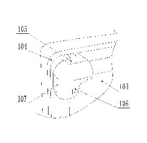
Referring to Fig. 6, the case body 103 may be divided into an upper case
body and a lower case body, when it is opened. Opening-closing frames 104
are provided at edges for closing of the upper case body and the lower case
body. When the case body 103 is closed, the opening-closing frames 104 of
the upper and lower case bodies correspond to each other, and the two
opening-closing frames abut against each other. When the case body 103 is
opened, the upper and lower case bodies are separated at the opening-closing
frames 104.
In order to make the description clearer and well understood, surfaces of the
case body 103 are classified here. The top corner of the case body 103 is a
region where three surfaces adjacent to each other intersect, in which one
surface is a top surface of the case body 103, and the other two surfaces are
side surfaces of the case body 103, among which one side surface contains
the opening-closing frame 104, and the other two side surfaces do not contain
the opening-closing frame 104. The bottom corner of the case body 103 is also
a region where three surfaces adjacent to each other intersect, in which one
surface is a bottom surface of the case body 103, and the other two surfaces
are side surfaces of the case body 103, among which one side surfaces
contains the opening-closing frame 104, and the other two side surfaces do not
contain the opening-closing frame 104. Herein, individual surfaces of the case
body 103 are named as follows: the surface at the top of the case body 103 is
named as a top surface; the surface at the bottom of the case body 103 is
named as a bottom surface; and for the side surfaces other than the top
surface and the bottom surface, the side surface containing the
opening-closing frame 104 is named as a first side surface, and the side
surface not containing the opening-closing frame 104 is named as a second
side surface.
Referring to Fig. 1, Fig. 1 shows the first cornerite 101 provided by
Embodiment 1 of the present application. The first cornerite 101 includes a
first
cornerite plate 105, a second cornerite plate 106 and a third cornerite plate
107. The first cornerite 101 wraps the top corner of the case body 103, with
the
first cornerite plate 105 fitting with the top surface of the case body 103,
the
second cornerite plate 106 fitting with the second side surface, and the third
cornerite plate 107 fitting with the first side surface.
Structurally, the first cornerite plate 105 is of an L-shaped structure having
two ends, in which one end abuts against the opening-closing frame 104, and
the other end approaches a corner. The right angel of the L-shaped structure
approaches an edge between the top surface and the side surface not
7
CA 02931865 2016-06-02
containing the opening-closing frame 104 of the case body 103. The second
cornerite plate 106 is also of an L-shaped structure, with a right angle side
approaching the corner.
The structure of the third cornerite plate 107 may not be specifically
defined,
which is preferably of a shape of rectangle and rounded off at edges in this
embodiment.
In accordance with Fig. 1, the first cornerite is exquisite in structure, and
convenient to process. The position where the first cornerite plate 105 of the
first cornerite abuts against the opening-closing frame is not located on the
edge between the top surface and the first side surface of the case body,
which reduces the total amount of arc walls of the first cornerite, thereby
facilitating processing. Meanwhile, when a stress is applied to the suitcase,
the
stress will not be centered on edges of the case body, and a part of the
stress
would be transmitted along the structure of the first cornerite, thereby
optimizing the force situation of the whole case body.
Any two of the first come rite plate 105, the second cornerite plate 106 and
the third cornerite plate 107 are connected with each other via an arc wall,
and
integrally formed, such that the first cornerite 101 has uniform stress
distribution and smooth and aesthetic appearance.
The first cornerite is made from metal, and roughly polished on the surface
thereof to improve the wear resistance thereof.
Referring to Figs. 2 to 5, Fig. 2 shows the second cornerite 102 provided by
Embodiment 1 of the present application.
A gap is provided between the outer cornerite 108 and the inner cornerite
109 of the second cornerite, facilitating assembling of the case body of the
suitcase. The inner cornerite 109 is fixedly connected onto the outer
cornerite
108, and the outer cornerite 108 is connected with the case body.
The case body is partially provided in the gap between the outer cornerite
108 and the inner cornerite 109, with the inner cornerite 109 serving as a
part
of an inner wall defining a storage space of the suitcase.
As shown in Figs. 3 and 4, the outer cornerite 108 includes a fourth cornerite
plate 110, a fifth cornerite plate 111 and a sixth cornerite plate 112. The
second cornerite 102 is used to wrap the bottom corner of the case body 103,
with the fourth cornerite plate 110 fitting with the first side surface of the
case
body 103, the fifth cornerite plate 111 fitting with the second side surface
of the
case body 103, and the sixth cornerite plate 112 fitting with the bottom
surface
of the case body 103.
Wrapping by the first cornerite and the second cornerite allows the wear
produced when the case body is laid flatWise to be mostly transferred onto the
cornerites, thus making the suitcase more wear resistant.
8
CA 02931865 2016-06-02
Referring to Fig. 4, a stepped surface is provided at the bottom of the sixth
cornerite plate 112, for the purpose of providing a space for disposing a
universal wheel 115. And in this way, the center of gravity of the case body
103
will not be too high, thereby enhancing the stability of the case body 103,
and
reducing the probability that the suitcase rolls over when being pushed.
Pushing is one way to move the suitcase. Specifically, the suitcase is moved
by directly applying a lateral thrust to the suitcase vertically positioned.
This
way saves effort, compared with a common way in which the suitcase is
moved by tilting the case body 103 and applying a forward and upward force to
the case body 103 via a draw-bar.
Referring to Fig. 5, one first through hole 113 is provided at a higher
surface
in the stepped surface of the six cornerite plate 112, and a corresponding
second through hole 114 is provided in the inner cornerite. When used, a
support shaft 116, with a threaded hole provided at the top thereof, of the
universal wheel 115 is inserted into the first through hole 113 from the
outside
of the sixth cornerite plate 112, and then screwed into a fixed bolt 117 by
passing through the second through hole 114 of the inner cornerite 109, such
that the fixed bolt 117 fits with the threaded hole at the top of the support
shaft
116, thereby assembling the universal wheel 115 onto the second cornerite
102.
The support shaft of the universal wheel extends into the case body, and is
connected by fitting with the second cornerite. Compared with the prior art,
this
way of connection makes it possible to provide a reliable limit to the support
shaft, producing a good fixation effect.
Referring to Fig. 3, in the second cornerite 102, each of the fourth cornerite
plate 110 and the fifth cornerite plate 111 is of an L-type structure, with a
right
angle position thereof approaching the bottom corner wrapped by the second
cornerite 102. The sixth cornerite plate 112 is in a shape of tetragonum. Any
two of the fourth cornerite plate 110, the fifth cornerite plate 111 and the
sixth
cornerite plate 112 are connected with each other via an arc wall, and
integrally formed, such that the outer cornerite 108 has uniform stress
distribution and smooth and aesthetic appearance.
The shape of the inner cornerite 109 is similar to that of the outer cornerite
108.
The first cornerite 101 and the second cornerite 102 are preferably riveted
with the case body 103. An unbounded number of unthreaded holes are
provided on the first cornerite 101 and the second cornerite 102, for
compatibility with the rivet connection. In the present embodiment, there are
preferably four unthreaded holes on the first cornerite 101.
For a conventional rectangular case body 103, four first cornerites 101 and
four second cornerites 102 may be provided, so as to protect individual
corners
9
CA 02931865 2016-06-02
and improve the compression resistance of the case body 103, thereby making
the suitcase more rugged, stable and durable.
In all examples illustrated and described herein, any specific value should be
interpreted as only being exemplary, rather than limiting. Therefore, other
examples of exemplary embodiments may have different values.
The outer cornerite of the second cornerite is made from metal, and is
roughly polished on the surface thereof to improve the wear resistance
thereof.
Referring to Fig. 6, Fig. 6 shows a suitcase provided by Embodiment 2 of the
present application.
The suitcase provided by Embodiment 2 includes a case body 103,
opening-closing frames 104, universal wheel assemblies, and a cornerite
device for a suitcase. The case body 103 includes an upper case body and a
lower case body rotatably connected with each other. Both contact surfaces of
the upper case body and the lower case body are connected to the
opening-closing frames 104. The cornerite device for a suitcase includes at
least two first cornerites 101 and at least two second cornerites 102. The
first
cornerites 101 are provided at top corners of the case body 103, the second
cornerites 102 are provided at bottom corners of the case body 103, and side
edges of the first cornerites 101 and the second cornerites 102 abut against
the respective opening-closing frames 104.
The universal wheel assembly includes a universal wheel and a support
shaft.
As shown in Fig. 6, the case body 103 of the suitcase provided by
Embodiment 2 is a conventional rectangular case body 103, with a top and a
bottom each having four corners. The number of the cornerite device can be
selected as required. Preferably, there are four first cornerites 101 and four
second cornerites 102.
In combination with Figs. 1 and 2, the first cornerite 101 is wrapped onto the
case body 103 from outside, and is fixed via rivet connection. The second
cornerite is fixed onto the case body 103 via rivet connection. The case body
103 is partially embedded in a gap between the outer cornerite 108 and the
inner cornerite 109.
The opening-closing frames 104 are provided at a joint of the upper case
body and the lower case body, with each of the upper case body and the lower
case body provided with one opening-closing frame 104. The opening-closing
frame 104 is made from hard material, which makes it stable in connection and
not easy to deform.
The first cornerite and the second cornerite improve the wear resistance and
compression resistance of the case body, ensuring the suitcase to be durable.
Meanwhile, the structure of the second cornerite improves the reliability in
CA 02931865 2016-06-02
connecting the support shaft of the universal wheel, reducing the probability
that the support shaft fails.
As to the cornerite device for a suitcase indicated in this embodiment of the
present application, the implementation principle and the resulted technical
effects are the same as those of the foregoing embodiments. For simplifity,
contents that the device embodiment does not mention may refer to related
contents in the foregoing embodiments.
In the present application, unless expressly specified and defined otherwise,
that "a first feature is 'above' or 'below' a second feature" may refer to
that the
first feature is in direct contact with the second feature, and also that the
first
feature is in contact with the second feature via an additional feature
therebetween, instead of the direct contact. Furthermore, that "the first
feature
is 'above', 'on' or 'over' the second feature" may refer to that the first
feature is
directly above or inclinedly above the second feature, or only refers to that
the
horizontal height of the first feature is higher than that of the second
feature.
That "the first feature is 'below', 'under' or 'underneath' the second
feature"
may refer to that the first feature is directly under or inclinedly under the
second feature, or only refers to that the horizontal height of the first
feature is
lower than that of the second feature.
It should be noted that, like reference signs and letters represent similar
items in the following drawings. Therefore, once defined in one accompanying
drawing, one item will not be required to be further defined and explained in
subsequent accompanying drawings.
The foregoing are only preferable embodiments of the present application,
and should not be considered as liming the present application. For those
skilled in the art, various modifications and variations may be made to the
present application. Any modifications, equivalent substitutions and
improvements, made within the spirit and principle of the present application,
should be included in the scope of protection of the present application.
11