Note: Descriptions are shown in the official language in which they were submitted.
CA 02932002 2016-05-27
WO 2015/088888
PCMJS2014/068692
METHOD OF INTERPRETING NMR SIGNALS TO GIVE MULTIPHASE
FLUID FLOW MEASUREMENTS FOR A GAS/LIQUID SYSTEM
FIELD OF THE INVENTION
[0001] The invention relates generally to a method and device for a magnetic
resonance-
based measurement and analysis of multi-phase flow regimes in a transport or
production
pipe. More particularly, the present invention relates to the determination of
liquid and gas
fractions in multi-phase flow.
BACKGROUND ON' THE INVENTION
[0002] Many techniques exist in the literature for using magnetic resonance
techniques for
direct, often real-time, analysis of various properties of liquids transported
through pipelines
For example, some properties of fluids extracted from a subsurface reservoir
can be
determined in real time and at in-situ reservoir temperatures and pressures
based on the
measurement of the fluid's transverse (T2) and longitudinal (Ti) relaxation
times, and as well
as their self-diffusivity (D). The parameters derived from such measurements
include, e.g.,
the relative fractions of hydrocarbons and water that have contributed to the
measured NMR
signal, the level of contamination of the hydrocarbon fluid phase by
infiltrations of water or
drilling mud, and estimations of hydrocarbon viscosity.
[0003] These measurements can be realized both as surface and subsurface
experiments and
often reduce ambiguities associated with samples extraction and sample
transport. Some
analytical methods based on Magnetic Resonance and its associated devices are
described,
for example, in the US Patents No 6,111,408, "Nuclear Magnetic Resonance
Sensing
Apparatus and for Techniques down hole Measurements;" U.S. 6,737,864 B2,
"Magnetic
Resonance Fluid Analysis and Method;' U.S. 6,825,657 B2, "Magnetic Resonance
for
Method Characterizing Fluid Samples Withdrawn from Subsurface Earth
Foimations;" U.S.
6,891,369 B2, "Magnetic Resonance Method and Logging for Apparatus Fluid
Analysis;"
U.S. 2005/0040822 Al, "Multi-measurements NMR Analysis based on Maximum
Entropy;"
U.S. 2006/0122779 Al, "Interpretation for Methods NMR Diffussion-T2 Maps;"
U.S.
7,872,474, "Magnetic Resonance Based Apparatus and Method to Analyze and to
Measure
the Bi-Directional Flow Regime in a Transport or a Production Conduit of
Complex Fluids,
in Real Time and Real Flow-Rate," U.S. 7,719,267, "Apparatus and Method for
Real Time
and Real Flow-Rates Measurements of Oil and Water Cuts from Oil Production,"
and the
references contained therein.
1
CA 02932002 2016-05-27
WO 2015/088888
PCT/US2014/068692
[0004] In US patent 4,785,245, magnetic resonance is used to determine the
relative fractions
of petroleum and water and the flow velocity in a fluid conduit. The
determination of
petroleum and water fractions is generally carried out by means of the
magnetic resonance
signal that is weighted by the individual spin-lattice relaxation times (Ti)
of either fluid
component. This technique requires that the individual transverse relaxation
time of the water
phase in the hydrocarbon/water mixtures differs from that of the oil phase.
For most
applications, this requirement is sufficiently fulfilled. In addition, for
hydrocarbon mixtures
comprised of low- and high viscosity components it is also often possible to
measure the ratio
of the light- and heavy components as long as their respective values of
longitudinal
relaxation times is sufficiently different to isolate the corresponding
magnetic resonance
signals.
[0005] For the measurement of flow-rates two basic principles can be
identified.
[0006] The determination of the fluid flow-rate through the measurement of
"flight time" of
fluids between two magnetic resonance spectrometers: (or between two sensors
of a single
spectrometer). See, for example, US patent 6,046,587 "Measurements of Flow
Fractions,
Flow Velocities and Flow Rates of a Multiphase Fluid using NMR Sensing," or US
patent
6,268,727 "Measurements of Flow Fractions, Flow Velocities and Flow Rates of a
Multiphase Fluid using ESR Sensing." Both patents disclose a sensor that uses
at least two
magnetic resonance spectrometers or one magnetic resonance and another
electron
paramagnetic resonance spectrometer. The basic principle of this approach is
based on what
is known as the "flight or passage time" of magnetic resonance-excited fluid
nuclei between
both spectrometers. Another variant of this method is US patent application
2004/001532,
"Method and procedure to measure fluid flow and fluid fraction, and equipment
used to that
end." In this case there is only one electronic part, shared by two sensor
coils. The operation
principle of the approach described in the '532 reference is the same as
outlined in the '727
reference, namely, the flow velocity of water and hydrocarbon molecules is
separately
measured via the respective time required for each component to straddle the
space between
the two sensor coils. While theoretically correct, this "time-of-flight"
approach has little
practical feasibility for oil-field applications, as it is limited to
relatively slow flow velocities
and is expensive to implement.
[0007] Another method for measuring fluid flow by means of magnetic resonance
is based on
the spatial encoding of the flow velocity by means of a magnetic field
gradient that is
oriented in the direction of the flow. This approach employs magnetic field
gradients (static
and/or electronically pulsed) to modulate the precession phase of protons
spins. A flow meter
2
CA 02932002 2016-05-27
WO 2015/088888
PCT/US2014/068692
with fluid phase separation that uses pulsed electromagnetic field gradients
is disclosed, for
instance, in US patents 6,452,390, "Magnetic Resonance Analyzing Flow Meter
and Flow
Measuring Method." This method has the disadvantage that the maximum flow
velocities
detectable are proportional to the intensity of the applied field gradient
pulses. Therefore, the
measurement of realistic flow velocities as encountered during hydrocarbon
production and
transport requires magnetic field gradients of high intensity, which also need
to be switched
on and off during extremely short time periods. Such gradient pulses are
difficult to achieve,
in particular across sensed volumes that are comparable to the cross-section
of conduits
typical used in oil-field applications. Consequently, this methodology is
generally restricted
to measurements of relatively low flow rates.
[0008] A version of this method that includes applying a permanent
longitudinal gradient
field is described in US patent application US 2006/0020403, "Device and
Method for real
time direct measurement of the Flow-Rate of a Multi-Component Complex Fluid."
The '403
reference discloses a flow meter and the measurement of fluid fractions in
multiphase flow by
one coil associated to a magnet of slightly oblique flat polar faces. The
device generates a
magnetic field gradient in the direction of fluid flow, in addition to the
constant magnetic
field required to detect the magnetic resonance signal. The spatial encoding
of the temporal
position of the resonant nuclei is realized by means of the linear magnetic
field gradient in the
volume that is probed by the excitation- and detection magnetic resonance
coil. For high flow
speeds, this gradient must be increased to achieve the corresponding encoding
of the protons
that compose the circulating complex fluid. While larger permanent magnetic
field gradients
can, in principle, be realized using different magnet shapes, this measurement
approach
reaches its limit because the increase in magnetic field gradient intensity is
accompanied by a
corresponding increase in the frequency content of the detected magnetic
resonance signal.
For a given bandwidth (of the electronics used for transmitting and receiving
the radio-
frequency signals), this broadening of the magnetic resonance line width¨as
represented in
the frequency domain after the time-domain signal has been Fourier-
transformed¨causes the
signal-to-noise ratio of the detected signal to deteriorate. This, in turn,
causes a reduction in
measurement precision and increases the time required for an individual
measurement.
Furthermore, it is possible that the detected NMR signal originates only from
fluids located
within a thin slice oriented perpendicular to the direction of the magnetic
field gradient rather
than from all fluids in the pipe.
3
81797161
[0009] The foregoing principles are advanced further in U.S. patents 8,143,887
and
8,212,557, the disclosures of which also include an exemplary system and
methods for
making NMR measurements of multiphase flow.
[0010] The approaches outlined above are limited to the measurement of the
average flow-
rates of the fluid components. It has been discovered, however, that because
these methods
rely on a quantifiable diffusion contrast between the liquid and gas phases,
they do not always
give accurate results at low gas pressures or low gas velocities. Thus it
remains desirable to
provide a method and apparatus that can more precisely assess the velocity
profile of each
individual component of a multiphase fluid without using time-of-flight
measurements.
SUMMARY OF THE INVENTION
[0011] According to preferred embodiments, the invention includes a method and
apparatus
that can more precisely assess the velocity profile of each individual
component of a
multiphase fluid without using time-of-flight measurements. Specifically, one
embodiment of
the present method comprises providing a measurement and analysis magnetic
resonance
module through which the multi-phase fluid flows and a pre-polarization module
through
which the multi-phase fluid flows before entering the magnetic resonance
module, flowing the
multi-phase fluid through the pre-polarization module and the magnetic
resonance module, as
the fluid flows through the magnetic resonance module, applying to the fluid
an radio-
frequency pulse sequence at least once in the presence of a magnetic field
gradient and at least
once in the absence of a magnetic field gradient and measuring the intensity
of a pre-
determined number of spin echoes that are produced by the RF pulse sequence,
using a first
calibration between the ratio of slope and intercept of the measured spin
echoes and flow
velocity for at least one non-gas phase with the magnetic field gradient
applied to determine
the flow velocity of that non-gas phase, using a second calibration of the
signal intensity of
the non-gas phases as function of flow velocity, with and without magnetic
field gradients
applied, to correct the gradient-induced attenuation of the non-gas signal and
to calculate a
gradient-corrected signal intensity of the non-gas phase, subtracting the
gradient-corrected
signal intensity of the non-gas phase from the NMR signal of the multi-phase
fluid measured
at the liquid flow velocity to determine signal that corresponds to the gas
phase, and using the
gas signal to determine the volumetric fraction and flow velocity of the gas
phase.
4
Date Recue/Date Received 2021-05-26
81797161
[0012] The radio-frequency pulse sequence may be a CPMG pulse sequence and the
magnetic
field gradient may be pulsed or constant during the RF sequence. The
determination of gas
flow velocity may include using a flow rate calibration for pure gas in
conjunction with the
slope and intercept of the calculated gas signal. The calculations of gas
volume and gas
velocity may be performed for a plurality of horizontal or non-horizontal
segments of the
cross-sectional area of the flow. Calculation of the volumetric flow rate of
the gas phase may
include multiplying the volume fraction of the gas by the gas flow velocity.
The present
method may advantageously be used to assess a multi-phase fluid that includes
a gas flowing
at a pressure less than 15 MPa.
[0013] According to one aspect of the present invention, there is provided a
method for
determining flow rates of gas and liquid phases in a multi-phase fluid flowing
in a pipe,
comprising:
a) providing a measurement and analysis magnetic resonance module through
which the multi-phase fluid flows;
b) providing a pre-polarization module through which the multi-phase fluid
flows
before entering the magnetic resonance module;
c) flowing the multi-phase fluid through the pre-polarization module and
the
magnetic resonance module;
d) as the multi-phase fluid flows through the magnetic resonance module,
applying to the multi-phase fluid a radio-frequency pulse sequence at least
once in the
presence of a magnetic field gradient and at least once in the absence of a
magnetic
field gradient and measuring the intensity of a pre-determined number of spin
echoes
that are produced by the RF pulse sequence;
e) using a first calibration between the ratio of slope and intercept of
the
measured spin echoes and flow velocity for at least one non-gas phase with the
magnetic field gradient applied to determine the flow velocity of that non-gas
phase;
using a second calibration of the signal intensity of the non-gas phases as a
function of flow velocity, with and without magnetic field gradients applied,
to correct
the gradient-induced attenuation of the non-gas signal and to calculate a
gradient-
corrected signal intensity of the non-gas phase;
Date Recue/Date Received 2021-05-26
81797161
g) subtracting the gradient-corrected signal intensity of the non-gas phase
from
the NMR signal of the multi-phase fluid measured at the liquid flow velocity
determined in step e) to determine a signal that corresponds to the gas phase;
and
h) determining the volumetric fraction and flow velocity of the gas phase,
wherein the
gas flow velocity is determined using a flow rate calibration for pure gas in
conjunction with the slope and intercept of the gas signal determined in step
g).
[0014] It will be understood that while the following description may include
references to
fluid flow in a single direction, the invention has equal applicability to bi-
directional flow.
[0015] Similarly, where the article "a" is used in a declaration of or in a
description of the
presence of a component in the apparatus of this invention, it must be
understood, unless this
declaration or description expresses explicitly the contrary, that the use of
the indefinite article
does not limit the presence of the component in the apparatus to one in
number.
BRIEF DESCRIPTION OF THE DRAWINGS
[0016] For ease in understanding the following description, reference is made
to the
accompanying Drawings, in which:
[0017] Figure 1 is a schematic illustration of a system capable of operating
in accordance with
the present invention;
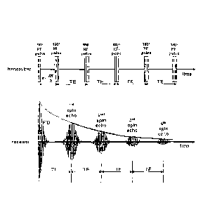
[0018] Figure 2 is a schematic illustration of a plot generated and used in
accordance with the
present invention;
[0019] Figure 3 is an illustration of the present methods applied to liquid-
gas measurements
for a water/methane flow in which water was flowing at 3.97 m3/hr, gas at 1
m3/hr;
[0020] Figures 4 and 5 are plots showing the correlation between calculated
and known
values for water and gas flow rates, respectively, at three different gas
volume fractions.
DETAILED DESCRIPTION OF A PREFERRED EMBODIMENT
[0021] Referring initially to Figure 1, a system capable of operating in
accordance
with the present invention preferably comprises a fluid flow line 10, a pre-
polarization module
12, a magnetic resonance module 14, and a controller 16. Flow line 10 may be
any line
capable of
5a
Date Recue/Date Received 2021-10-25
CA 02932002 2016-05-27
WO 2015/088888
PCT/US2014/068692
carrying a fluid, and preferably capable of carrying a multiphase fluid. Flow
line 10 is
preferably horizontal and may in some instances be a pipe such as are used for
transporting
crude oil or other hydrocarbon products, which may in turn include gaseous
and/or liquid
hydrocarbons and liquid water or other hydrogen-bearing contaminants, such as
H2S . Flow
line 10 passes through pre-polarization module 12 and magnetic resonance
module 14,
preferably concentrically, so that fluid flowing through line 10 is exposed to
the magnetic
fields applied by pre-polarization module 12 and magnetic resonance module 14.
[0022] Pre-polarization module 12 comprises a means for providing a magnetic
field and
preferably hut not necessarily comprises a means for providing a magnetic
field of variable
effective length. In some embodiments, pre-polarization module 12 may comprise
one or
more Halbach arrays of magnets.
[0023] Magnetic resonance module 14 preferably includes at least one coil
capable of
applying a radiofrequency (RF) pulse sequence. The coil may be wound in a
solenoid
configuration, a saddle configuration or in any other suitable configuration
that results in
application of a predictable magnetic field oriented perpendicularly to the
background
magnetic field, and covering the entire volume of fluid inside module 14.
[0024] Flow line 10 is preferably constructed from non-magnetic materials for
the section
located inside the pre-polarization modules, and is constructed from non-
conductive materials
for the section located inside the magnetic resonance module. If the RF- and
gradient coils
are mounted on the inside of the pipe, however, flow line 10 can be
constructed from a non-
magnetic but electrically conductive pipe material, such as stainless steel.
[0025] Still referring to Figure 1, pre-polarization module 12 and magnetic
resonance module
14 are preferably controlled by controller 16, which is preferably a
microprocessor/computer
such as are known in the art. If desired, controller 16 can be located
remotely from modules
12 and 14 so as to simplify compliance with oil-field regulations.
[0026] In preferred embodiments, in order to ensure that laminar flow is
established before
the fluid enters the module, the system also includes a sufficient length of
straight pipe
upstream of the pre-polarization module 12. The length of straight pipe needed
to ensure
laminar flow depends on the range of expected fluid velocities in the pipe and
may be a few
to several meters.
[0027] It is also preferred but not necessary that the In of meter he matched
to and aligned as
precisely as possible with the inside diameter of the pipe upstream of the
meter, so as to
minimize turbulent flow into the meter.
6
CA 02932002 2016-05-27
WO 2015/088888
PCT/US2014/068692
[0028] Also preferably provided is a magnetic field "catcher" that functions
to remove any
metallic debris from the fluid before it enters the meter. It is very common
in the production
of hydrocarbons that the produced fluid contains metallic debris from various
sources,
including particles of metal that have been scraped or chipped off the bit and
other downhole
tools, and other random metal fragments that may be present in the borehole.
The magnetic
field catcher is preferably positioned near the meter and upstream of it in
the flow line, but far
enough away to ensure that its magnetic field does not interfere with
operation of the meter
and that the magnetic polarization of fluids induced by the catcher has
disappeared before
fluids enter the pre-polarization module 12.
[0029] Finally, it is preferable to position and mount the meter so that it is
mechanically
isolated from vibration sources such as pumps and other equipment.
[0030] Still referring to Figure 1, as will be understood, pre-polarization
module 12 serves to
orient certain atomic nuclei into a uniform orientation as they pass through
it. Among the
types of nuclei that can he oriented are those having an odd number of protons
(1H) or
neutrons (13C) or both protons and neutrons (211). Because hydrogen is
abundant in both
gaseous and liquid hydrocarbons and in water, it is useful to be able to
assess the presence of
hydrogen in typical oilfield fluids. Magnetic resonance module 14 serves as
both a transmitter
and a sensor, although not simultaneously. The magnetic field caused by the
oriented nuclei
is detectable by magnetic resonance module 14.
100311 For a fluid flowing through the system, magnetic resonance module 14
will sense a
diminishing field in which the reduction in signal amplitude over time is a
result of both the
flow of oriented nuclei out of magnetic resonance module 14 as well as the
natural decay of
the oriented state and the loss of phase coherence of precessing spins.
100321 According to preferred embodiments of the invention, pre-polarization
module 12 is
operated for a desired interval and then changes effective length, while
magnetic resonance
module 14 applies a pulsed magnetic field to the fluid. During its "off"
cycles, magnetic
resonance module 14 acts as a sensor.
[0033] Figure 2 illustrates the output from magnetic resonance module 14 and
the signal
sensed by it during a typical pulse sequence. The amplitude of the sensed
field diminishes
over time. Again, the reduction in amplitude over time is a result of both the
flow of oriented
nuclei out of magnetic resonance module 14 and the natural decay of the
oriented state.
Collected over the duration of each pulse sequence, these measurements are
indicative of the
volume fractions of at least two phases in a multi-phase fluid. As set out in
U.S. Patents
7,719,267 and 7,872,474, for short-time approximations and reasonable flow
rates, the
7
CA 02932002 2016-05-27
WO 2015/088888
PCT/US2014/068692
measured decay is often dominated by the flow of oriented nuclei and can be
used as a flow
measurement.
100341 By way of example, a first measurement is made using a pulse sequence
adapted to
measure the transverse NMR relaxation time, T2. An example of a suitable
sequence is a Can
Purcell Meiboom Gill (CPMG) sequence. As is known in the art, a CPMG sequence
is a spin
echo pulse sequence consisting of a 90' radio frequency pulse followed by a
train of
successive 1800 pulses, as illustrated with reference to the transmitter in
Figure 2. Typically,
several hundreds to a few thousands of these RF pulses are applied in a single
sequence. The
resulting free induction decay (FID) and spin echoes are detected by the
receiver of the flow
meter after the initial 90 radio frequency pulse and between the 180 radio
frequency pulses,
as illustrated with reference to the receiver in Figure 2. As can be seen, the
envelope of the
spin echo maxima decays exponentially with the time constant T2. The
extrapolation of the
spin echo envelope to time zero, or the initial amplitude of the FID signal,
yields the net
magnetization. After calibration, the net magnetization is a direct measure of
the number of
nuclei in resonance and, hence, of fluid volume. Thus, in preferred
embodiments, the
slope/intercept detennination is used in conjunction with a previously
established calibration
to detennine flow velocity. These concepts are described at length in M. Appel
and J.J.
Freeman, and D. Pusiol, 2011. Robust Multi-Phase Flow Measurement Using
Magnetic
Resonance Technology. Paper SPE 141465 presented at the at the SPE Middle East
Oil and
Gas Show and Conference held in Manama, Bahrain, 6-9 March 2011.
[0035] It has been detennined that the foregoing technique is insufficient for
measuring gas-
liquid flow. To address that deficiency a new method has been discovered,
which does not
rely on a quantifiable diffusion contrast between the liquid and the gas
phase. The new
technique relies on the contrast in hydrogen indices between the gas phase,
typically
methane, and the liquid phase(s).
[0036] The derivation of hydrogen indices for reservoir fluids has been
extensively
discussed in the art. For proton (1H) NMR purposes, the hydrogen index (HI) is
defined as
the ratio of the amount of hydrogen in the sample and the amount of hydrogen
in pure water
at standard conditions (STP):
8
CA 02932002 2016-05-27
WO 2015/088888
PCT/US2014/068692
= Amount of hydrogen in sample
HI
Amount of hydrogen in pure water at STP
moles H/cm3
(1)
0.111
=p,,Nõ I M
0.111
where põ, is the mass density of the fluid in g/cm3, NH is the number of
hydrogen atoms in
the molecule, and M is the molecular weight of the fluid. The denominator of
the last
expression, 0.111, represents the moles of hydrogen in one cubic centimeter of
water at
standard conditions. Consequently, the numerator is the number of moles of
hydrogen in the
same volume of the bulk sample at the conditions of the measurement.
[0037] The initial amplitude of a CPMG measurement as discussed above, without
any field
gradient, represents the fractions of the fluids in the sensed section of the
pipe, weighted by
the effect of outflow and hydrogen indices. At flowing tubing head pressures
up to 1000 to
2000 psi, the signal of methane contributes to only 10% - 15% of the measured
NMR signal
because of the low gas hydrogen index.
[0038] If a constant magnetic field gradient is applied during the entire CPMG
pulse
sequence, the entire NMR signal will be further attenuated proportionally to
the intensity of
the magnetic field gradient, the duration between subsequent 180 pulses, and
the diffusivity
of the fluids. It is understood that this constant magnetic gradient reduces
the thickness of the
tested slice; however, due to the broad bandwidth of the RF receiver and the
low gradient
intensity, the measured slice is typically still broader than the pipe cross-
section.
[0039] Due to the high diffusion coefficient of a gas, at a given number of
acquisition
repetitions, the gradient-induced attenuation of the entire measured signal
results in a
suppression of the gas signal below detection levels. At the same time, the
less diffusive
liquid signal will still be measurable because of its higher initial (non-
gradient) signal and
strength. As a consequence, the NMR signal that is detected when a constant
magnetic field
gradients is applied will be dominated by the water- and oil responses.
[0040] Using a calibration between the ratio of slope and intercept and flow
velocity for the
individual liquid phases with the magnetic field gradient switched on during
the CPMG RF
pulse sequence, the flow velocity of the liquid phase can he determined. The
magnetic field
gradient may be constant or pulsed during the CPMG RF pulse sequence.
[0041] A second calibration between the signal intensity of the pure liquid
phases as a
function of flow velocity, with and without magnetic field gradient pulses
applied, can be
9
CA 02932002 2016-05-27
WO 2015/088888
PCT/US2014/068692
used to correct the gradient-induced attenuation of the liquid signal and to
calculate the
gradient-corrected signal intensity of the liquid phase in the absence of a
constant gradient.
100421 The ratio of the gradient-corrected intensity of the liquid phase to
the intensity of the
NMR signal of pure liquids measured at the previously-deteimined liquid flow
velocity can
be used to calculate the volumetric fraction of the liquid phase.
[0043] Further, subtracting the gradient-corrected liquid signal from the
signal obtained in
the absence of applied constant gradients yields the gas signal. The slope and
intercept of this
differential gas signal can be calibrated to gas flow velocity using a flow
rate calibration for
pure gas. The volumetric fraction of the liquid phase can be used to determine
the volume
fraction of gas. Multiplying this gas volume fraction by the previously-
determined gas flow
velocity and the cross-sectional area of the pipe gives the volumetric flow
rate of the gas
phase.
[0044] The foregoing interpretation method has been successfully applied to
several
water/gas measurements. By way of example, Figure 3 illustrates this procedure
for water
flowing at approximately 4 m3/hr, and gas flowing at 1 m3/hr. In Figure 3,
line 32 represents a
CPMG measurement as discussed above, without any field gradients applied, line
34
represents the signal received in the presence of a gradient, line 36
represents the gradient-
corrected signal intensity of the liquid phase in the absence of a constant
gradient, and line 38
represents the gas signal obtained by subtracting the gradient-corrected
liquid signal 36 from
the original gradient-free signal 32.
[0045] Figures 4 and 5 show the correlation between known flow rates and the
results
obtained using the method described above for water and gas fractions,
respectively. The
measurements covered three different gas-volume fractions and a variety of
flow rates. As
can be seen, the correlation between known and calculated values is high,
especially for the
liquid phase. Using horizontal sight glasses, it was noted that at a constant
gas-volume
fraction, the cross-sectional area occupied by gas decreased with increasing
flow rate. This
illustrates increasing slip velocity of the gas phase, and also implies that
the water flow
velocity increases less than proportionally with increasing flow rate because
of a larger cross-
sectional area available for flow. In addition, the changing cross-sectional
areas demonstrate
that the measurement of the combined fluid density does not provide
information about the
volumetric flow fractions
[0046] In preferred embodiments, the system is configured to sense the signals
received from
each of a series of horizontal segments of the flow volume. Because less-dense
fluids, such as
gas, will migrate to the top in a multiphase system, "slicing" the flow
horizontally allows the
CA 02932002 2016-05-27
WO 2015/088888
PCT/US2014/068692
application of the method mentioned above for individual sections of
stratified flow. Fluid
composition and velocity(ies) can therefore be deteimined for each "slice" and
it becomes
possible to obtain more accurate characterization of the total flow.
[0047] The present invention has been found to provide meaningful
characterization of fluid
flows through the magnetic resonance module at less than 0.3 mills, and even
less than 0.2 m/s.
Similarly, the present invention has been found to provide meaningful
characterization of
multi-phase fluid flows that include a gas and the gas flows through the
magnetic resonance
module at a pressure less than 15 MPa, or even less than 8 MPa.
[0048] While preferred embodiments of this disclosure have been described with
respect to
characterizing hydrocarbon/water mixtures, the invention is not limited to oil-
field
applications. The present invention is preferably but not necessarily applied
in an oil
production line, or in other conduits transporting multiphase fluids, for
surface, subsurface,
on- and offshore applications. For example, the measurement approach outlined
herein can
also be applied to any other technological field in which it is desirable to
determine the make-
up of a multi-phase fluid.
11