Note: Descriptions are shown in the official language in which they were submitted.
CA 02932080 2016-06-03
-
OPTICAL DEVICES, AND THEIR USE FOR SECURITY AND AUTHENTICATION
-
FIELD OF THE INVENTION
This invention relates to the field of optical devices, in particular optical
devices the perceivable or detectable appearance of which changes according to
the
orientation of the device. The invention also relates to the field of optical
devices for
authentication of security items and documents, including but not limited to
banknotes.
BACKGROUND TO THE INVENTION
Optical devices that are difficult to manufacture, replicate or reverse-
engineer, play a key role in anti-counterfeit efforts. Such devices may be
affixed to or
incorporated into items or documents of importance or value, thus enabling a
user to
check for authenticity by study or analysis of observable or detectable
optical
features of the device. Typically, such devices comprise layered or multi-
layered
structures where user manipulation of the device, or a user-initiated external
influence upon the device, causes a change in appearance of the device, or at
least a
portion thereof. The change in appearance may result from some physical or
chemical change that occurs upon user manipulation of the device.
Alternatively,
there may be no physical or chemical change upon user manipulation of the
device.
Instead, the apparent change in appearance may only comprise a change in a
user's
perception of the device, for example when viewed at different angles or under
different ambient or incident light conditions.
Often, such optical devices are planar and thin (e.g. thin films), such that
when applied to a substrate they appear flush with the substrate without
protruding
significantly from the substrate. In the case where the optical devices are
applied to
a flexible substrate such as plastic or paper, the devices themselves may also
be
flexible or foldable such that they conform to the contours of the substrate
during
use.
1
CA 02932080 2016-06-03
. -
In the 'fight' against counterfeiting, there remains a constant need in the
art
. -
to develop new optical devices that are readily perceivable or detectable to a
user or
consumer, but which exhibit optical properties that are conspicuous yet
difficult to
replicate. The need extends to optical devices with both relatively simple
content,
and also to devices with more complex content, including devices that are
single use
or that can repeatedly undergo a perceived change in optical or physical
characteristics. Ideally, though not necessarily, there is a need for such
devices that
can be manufactured in a relatively simple and inexpensive manner. The need
for
such devices extends into multiple disciplines, including but not limited to
interactive
media material, advertisements, magazines, books or other items with user-
manipulated content, advertizing billboards, and authentication devices for
security
documents such as passports, credit cards and banknotes to help prevent
counterfeit.
SUMMARY
It is an object of selected embodiments to provide an optical device with
optical properties that are characteristic of the device, which can be
observed or
detected by a user.
It is a further object of selected embodiments to provide an item or
document, such as a security item or document, comprising an optical device as
described herein attached to or otherwise incorporated into the device.
The following embodiments are exemplary:
In exemplary embodiment 1 there is provided an optical device comprising:
a. a luminescent material that upon stimulation emits luminescent
radiation of at least one peak output wavelength; and
b. an angle-dependent optical filter coupled to the luminescent material,
the luminescent radiation transmitted through and emitted from the
filter in an angle dependent manner, such that inspection whilst
progressively tilting the device (e.g. through 45 degrees) causes at
2
CA 02932080 2016-06-03
least one colour or fraction of the luminescent radiation emanating
from the device to be observable or detectable external to the device.
In exemplary embodiment 2 there is provided the optical device of
embodiment 1, wherein the optical filter coupled to the luminescent material
selectively emits the luminescent radiation from the device at one or more
peak
output angles, with at least 70% of the luminescent radiation produced by the
luminescent material emitted from the device at, or within 15 degrees from,
the one
or more peak output angles.
In exemplary embodiment 3 there is provided the optical device of
embodiment 2, wherein the optical filter causes at least 80% of the
luminescent
radiation to be emitted at, or within 10 degrees from, two or more peak output
angles, with fractions of the luminescent radiation emitted from the device
momentarily observable or detectable at different output angles as the device
is
progressively tilted.
In exemplary embodiment 4 there is provided the optical device of
embodiment 2, wherein the optical filter causes at least 90% of the
luminescent
radiation to be emitted at, or within 5 degrees from, three or more peak
output
angles, with three or more fractions of the luminescent radiation emitted from
the
device momentarily observable or detectable at different output angles as the
device
is progressively tilted.
In exemplary embodiment 5 there is provided the optical device of
embodiment 1, wherein the luminescent material emits a luminescent radiation
with
a full wave half maximum (FWHM) of 50nm or less.
In exemplary embodiment 6 there is provided the optical device of
.. embodiment 1, wherein the luminescent material emits a luminescent
radiation with
a full wave half maximum (FWHM) of 25nm or less.
In exemplary embodiment 7 there is provided the optical device of
embodiment 1, wherein the luminescent material emits a luminescent radiation
with
a full wave half maximum (FWHM) of 10nm or less.
3
CA 02932080 2016-06-03
. -
In exemplary embodiment 8 there is provided the optical device of
. .
embodiment 1, wherein the luminescent material is stimulated to produce
luminescent radiation by incident ultraviolet light.
In exemplary embodiment 9 there is provided the optical device of
embodiment 1, wherein the optical filter comprises an optical interference
structure,
such as a Fabry Perot structure, a Bragg stack, or thin-film filter or foil.
In exemplary embodiment 10 there is provided the optical device of
embodiment 1, wherein the luminescent material and the optical filter are
matched
in terms of the specificity of the optical filter to filter radiation of a
wavelength
corresponding to the at least one peak output wavelength of the luminescent
radiation, in an angle-dependent manner.
In exemplary embodiment 11 there is provided the optical device of
embodiment 1, wherein the luminescent material, when stimulated, produces
luminescent radiation of more than one peak output wavelength for angle-
dependent filtering by the optical filter, the luminescent radiation of one
wavelength
emitted from the device at one or more peak output angles that are the same or
different from the peak output angles of luminescent radiation of at least one
other
wavelength, with different fractions of the luminescent radiation emitted from
the
device with different colours or wavelengths momentarily and separably
observable
or detectable as the device is progressively tilted.
In exemplary embodiment 12 there is provided the optical device of
embodiment 1, wherein the device comprises more than one type of luminescent
material, each producing when stimulated luminescent radiation of a peak
output
wavelength that is different to the other types of luminescent material(s)
present, so
that the device produces luminescent radiation of more than one peak output
wavelength, for angle-dependent filtering by the optical filter, the
luminescent
radiation of one wavelength emitted from the device at one or more peak output
angles that are the same or different from the peak output angles of
luminescent
radiation of at least one other wavelength, with different fractions of the
4
CA 02932080 2016-06-03
. -
luminescent radiation emitted from the device with different colours or
wavelengths
.. -
momentarily and separably observable or detectable as the device is
progressively
tilted.
In exemplary embodiment 13 there is provided a use of an optical device of
any one of embodiments 1 to 12, to provide authentication to a security item
or
document.
In exemplary embodiment 14 there is provided the use of embodiment 13,
wherein the security document is a banknote.
In exemplary embodiment 15 there is provided a security item, security card
or security document, comprising a substrate with the optical device of any
one of
embodiments 1 to 12 affixed or adhered thereto.
In exemplary embodiment 16 there is provided the security item, security
card or security document of embodiment 15, which is a banknote.
In exemplary embodiment 17 there is provided a method for determining
whether a security item, security card or security document is a legitimate or
counterfeit item, card or document, the item, card or document comprising an
optical device of any one of embodiments 1 to 12, the method comprising the
steps
of: illuminating the optical device with radiation of a wavelength suitable to
stimulate
the luminescent material or materials present; progressively tilting the item,
card or
document whilst the device emits luminescent radiation; and observing or
detecting
at least one fraction of said luminescent radiation emitted from the device.
In exemplary embodiment 18 there is provided the method of embodiment
17, wherein a predetermined spatial pattern of detected or observed fractions
of
luminescent radiation as the device is progressively tilted is indicative that
the device
is legitimate and not counterfeit.
In exemplary embodiment 19 there is provided a method for improving the
security of a security item, security card or security document, to help
prevent
counterfeit thereof, the method comprising: adhering or affixing an optical
device of
any one of embodiments 1 to 12 to the item, card or document.
5
CA 02932080 2016-06-03
In exemplary embodiment 20 there is provided method of embodiment 19,
wherein the item, card or document is a banknote.
In exemplary embodiment 21 there is provided the method of any one of
embodiments 17 to 20 wherein the step of tilting is performed by a human or a
machine.
In exemplary embodiment 22 there is provided a method for determining
whether a security item, security card or security document is a legitimate or
counterfeit item, card or document, the item, card or document comprising an
optical device as described herein, the method comprising the steps of:
illuminating
the optical device with radiation of a wavelength suitable to stimulate the
luminescent material or materials present; positioning a plurality of sensors
at a
plurality of positions or angles relative to the optical device whilst the
optical device
emits luminescent radiation; and detecting with said sensors at least one
fraction of
said luminescent radiation emitted from the optical device.
In exemplary embodiment 23 there is provided the method of exemplary
embodiment 22, further comprising one or more of the following optional steps:
calculating and optionally displaying the detected output angles for the
luminescent
radiation from the device, and optionally comparing the detected output angles
with
predetermined output angles known to correlate with legitimate optical
devices.
In exemplary embodiment 24 there is provided an authentication device, to
test whether a security item, security card or security document comprising an
optical device of any one of embodiments 1 to 12 is legitimate or counterfeit,
the
authentication device comprising:
optionally a holder to hold the item, card or document being tested;
a source of electromagnetic radiation suitable to stimulate the luminescent
material of the optical device; and
one or more sensors to gather information regarding angles of emission of
luminescent radiation from the device;
6
CA 02932080 2016-06-03
-
optionally movement means to move the one or more sensors and the item
-
or document relative to one another, to enable the one or more sensors to
scan for different angles of emission of luminescent radiation from the
device;
a comparison component to compare sensed angles of emission of
luminescent radiation from the optical device with predetermined angles of
emission known to be indicative of an authentic optical device, and therefore
indicative an authentic item, card or document comprising the optical device.
In exemplary embodiment 25 there is provided the authentication device of
embodiment 24, further comprising an output component to provide a visual or
electronic signal indicative of whether the item, card or document comprising
the
optical device is authentic or counterfeit.
In exemplary embodiment 26 there is provided the authentication device of
claim 24, wherein a plurality of sensors are present each to detect
luminescent
radiation emitted at a different emission angles from the device so that the
plurality
of sensors gather information regarding angles of emission of luminescent
radiation
from the device without need to move the sensors and the item or document
relative
to one another.
BRIEF DESCRIPTION OF THE DRAWINGS
Figure la provides a schematic cross-sectional view of an example optical
device at
an angle theta of 45 degrees between a user's line of sight and a plane of the
substrate to which the device is applied.
Figure lb provides a schematic cross-sectional view of the same example
optical
device as illustrated in Figure la, at an angle theta of 60 degrees between a
user's
line of sight and a plane of the substrate to which the device is applied.
Figure 2a provides a graph to compare schematically both luminescent radiation
intensity and optical filter transmission with wavelength, for the optical
device as
shown in Figure la.
7
CA 02932080 2016-06-03
, -
Figure 2b provides a graph to compare schematically both luminescent radiation
. -
intensity and optical filter transmission with wavelength, for the optical
device as
shown in Figure lb.
Figure 3a provides a schematic cross-sectional view of an example optical
device at
an angle theta of 45 degrees between a user's line of sight and a plane of the
substrate to which the device is applied.
Figure 3b provides a schematic cross-sectional view of the same example
optical
device as illustrated in Figure 3a, at an angle theta of 60 degrees between a
user's
line of sight and a plane of the substrate to which the device is applied.
Figure 4a provides a graph to compare schematically both luminescent radiation
intensity and optical filter transmission with wavelength, for the optical
device as
shown in Figure 3a.
Figure 4b provides a graph to compare schematically both luminescent radiation
intensity and optical filter transmission with wavelength, for the optical
device as
shown in Figure 3b.
Figure 5a provides a schematic cross-sectional view of an example optical
device at
an angle theta of 45 degrees between a user's line of sight and a plane of the
substrate to which the device is applied.
Figure 5b provides a schematic cross-sectional view of the same example
optical
device as illustrated in Figure 5a, at an angle theta of 60 degrees between a
user's
line of sight and a plane of the substrate to which the device is applied.
Figure Sc provides a schematic cross-sectional view of the same example
optical
device as illustrated in Figure 5a, at an angle theta of 75 degrees between a
user's
line of sight and a plane of the substrate to which the device is applied.
Figure 6a provides a graph to compare schematically both luminescent radiation
intensity and optical filter transmission with wavelength, for the optical
device as
shown in Figure 5a.
8
CA 02932080 2016-06-03
_
Figure 6b provides a graph to compare schematically both luminescent radiation
. -
intensity and optical filter transmission with wavelength, for the optical
device as
shown in Figure 5b.
Figure 6c provides a graph to compare schematically both luminescent radiation
intensity and optical filter transmission with wavelength, for the optical
device as
shown in Figure Sc.
Figure 7a illustrates the appearance of an example optical device at a first
angle theta
between a user's line of sight and a plane of the substrate to which the
device is
applied.
Figure 7b illustrates the appearance of the same example optical device as
that
shown in Figure 7a, at a second angle theta between a user's line of sight and
a plane
of the substrate to which the device is applied.
Figure 7c illustrates the appearance of the same example optical device as
that
shown in Figure 7a, at a third angle theta between a user's line of sight and
a plane of
the substrate to which the device is applied.
Figure 8a provides a schematic cross-sectional view of an example optical
device at
an angle theta of 45 degrees between a user's line of sight and a plane of the
substrate to which the device is applied.
Figure 8b provides a graph to compare schematically both luminescent radiation
intensity and optical filter transmission with wavelength, for the optical
device as
shown in Figure 8b.
DEFINITIONS:
"Angle theta": refers to the smallest angle between a line of sight of a user
of a
device as disclosed herein, and a plane of the substrate to which the device
is
attached, or the plane of the device itself.
9
CA 02932080 2016-06-03
-
"Flash": refers to a brief or momentary detection of emitted electromagnetic
radiation from a device as described herein. It will be understood that the
devices
disclosed herein do not actively flash on and off, because they are generally
static in
terms of their physical structure and function, and do not necessarily undergo
a
dynamic physical or chemical change. Thus the term "flash" refers to what may
be
perceived by a user of the device under stimulation by incident radiation, for
example whilst the device is progressively tilted relative to the user (or
detection
device). In this way a narrow band of emitted luminescent radiation,
continuously
emitted at or near to a specific peak emission angle, is caused to pass across
a line of
sight of a user or detector, such that it at least appears from the user's
perspective
that a "flash" of luminescent radiation has been emitted from the device.
Item: refers to any object, document, substrate or material to which a device
as
described herein is applied, either permanently or temporarily. For example,
in
selected embodiments the item may be subject to counterfeit risks, such that
the
presence of an optical device as described herein affixed to or otherwise
incorporated into the item may be indicative that the item is authentic or
legitimate,
and not counterfeit.
"Momentary": refers typically to a time period of 3 seconds or less, 2 seconds
or less,
1 second or less, 0.5 seconds or less, or 0.1 second or less. These time
periods
typically related to a "flash" of emitted luminescent radiation typically
observed
during progressive tilting of a device as disclosed herein relative to a user
of the
device at a constant rate for example of 10 degrees of tilt per second.
Optical properties: refers to the electromagnetic radiation reflected,
transmitted,
emitted or otherwise received from an optical device as herein described, that
is
visible to the naked eye of an observer, or is observable to an observer with
the
assistance of a screening or scanning tool. For example, where the optical
properties
of a device, or a change in such properties, are detectable only using
incident UV or
CA 02932080 2016-06-03
other beyond visible electromagnetic radiation, a corresponding screening tool
may
be one that emits UV radiation and directs the radiation onto the optical
device
under analysis. The optical properties of any device or element thereof as
herein
described may be caused, influenced or occur due to the material properties of
the
device, the degree of reflection, transmission, absorption, refraction or
other
modification of electromagnetic radiation incident thereupon, and may also
depend
upon the orientation, shape, structure, nanoscale properties, or other
material
properties of the device or element when taken alone or in combination with
other
devices, elements or device components.
"Peak output angle": refers to an angle of emission for luminescent radiation
being
emitted from a device as disclosed herein in an angle-dependent manner due to
the
presence of an optical filter, and specifically the angle of the greatest
intensity of
emission compared to that of adjacent angles of emission. For any device, the
optical
filter may be such that multiple peak output angles may be present for a
device,
which may be the same or different in terms of their peak intensities.
"Peak output wavelength": refers to the luminescent radiation emitted from
luminescent material of a device as disclosed herein, and specifically to the
wavelength of the radiation at the greatest intensity for the radiation.
Perceivable or detectable change (of optical properties of an optical device):
refers to
any change that occurs to a device as described herein, that may be perceived
by the
user of a device (through sight, touch etc.) or which is detected for example
by a user
of the device with the assistance of a screening tool. To provide just one
example, a
change of optical properties of a device might occur only in the beyond
visible
spectrum of electromagnetic radiation, in which case a user of the device may
choose to employ a UV screening tool to detect a corresponding change in
optical
properties. For clarity, a perceivable or detectable change of optical
properties of an
optical device as disclosed herein does not necessarily result from a physical
or
11
. -
chemical change in the device, but rather a perception (visual or detected)
from a
. _
perspective of a user or detection apparatus.
Polymer core material: refers to any polymer or polymer-like substance
suitable to
form a substrate of an item or document. For example, the material may be in
the
form of a sheet-like configuration to be formed or cut into a size suitable
for use in
various items and documents. The polymer core material may be a substantially
uniform sheet of polymer material, or may take the form of a laminate
structure with
layers or polymer film adhered together for structural integrity, such as
disclosed for
example in international patent publication W083/00659 published March 3,
1983.
A polymer core material may also
comprise a material that includes a polymer in combination with other
materials such
as plastic or paper to form a hybrid core material.
Reflected light: refers to light incident upon a surface and subsequently
'bounced' or
otherwise reflected by that surface such that the reflected light is visible
to the naked
eye or detectable by a suitable means. The degree of light reflection may vary
according to the surface, and the degree of light that is not reflected by the
surface
because it is scattered by, diffracted by, absorbed by, or transmitted through
the
surface and the material of the substrate.
Security document: refers to any document, item or article of manufacture of
any
importance or value, which is or might possibly be subject to or susceptible
to
counterfeit copying. In selected embodiments, a security document may include
features or devices intended to show that the document, item or article is a
genuine
and legitimate version, and not a counterfeit copy of such a document, item or
article. For example, such security documents may include security features
such as
those disclosed herein. Such security documents may include, but are not
limited to,
identification documents such as passports, citizenship or residency
documents,
12
Date Recue/Date Received 2022-11-01
CA 02932080 2016-06-03
drivers' licenses, banknotes, cheques, credit cards, bank cards, and other
documents,
as well as labeling or other security features, for items of monetary value
such as
designer clothing, accessories, or any other branded products where it is
desired to
indicate or demonstrate the authenticity or legitimacy of the product compared
to a
counterfeit copy. Such security features may be permanently or removably
incorporated therein depending upon the nature of the document, item or
article,
and the intended end user.
Substrate / core material: refers to any material used to form the main
substrate,
structure or sheet of any item or document as described herein. In select
embodiments, the material may be formed into a sheet or member, and may be
composed of a substance selected from but not limited to paper, a plastic, a
polymer,
a resin, a fibrous material or the like, or combinations thereof. In selected
embodiments the core material is of a material suitable for application
thereto,
either directly or indirectly, of an optically variable device of the types
disclosed
herein. The optically variable device, or elements thereof, may be applied or
attached to the core material in any manner including the use of adhesive
materials
or layers, such as glues, or by overlaying an adhesive substance, film,
varnish or other
material over the top of the device or components thereof. The core material
may
be smooth or textured, fibrous or of uniform consistency. Moreover, the core
material may be rigid or substantially rigid, or flexible, bendable or
foldable as
required by the document. The core material may be treated or modified in any
way
in the production of the final document. For example, the core material may be
printed on, coated, impregnated, or otherwise modified in any other way.
Transmitted light: refers to light that is incident upon a surface, layer or
multiple
layers, of which a portion of the light is able to pass through and / or
interact in some
way with the surface, layer or layers by transmission. Light may be
transmitted
through a layer or layers by virtue of the layer or layers not being entirely
opaque,
13
CA 02932080 2016-06-03
but instead permitting at least a portion (e.g. 0-99%) of the incident light
to be
transmitted through the layer or layers in view of the layer or layers
exhibiting at
least some degree of translucency.
Window: refers to a region or portion of a security document in which a
component
of a security device is exposed for visual inspection, because there is little
or no
translucent or opaque material to obscure the view of the exposed portions. A
window may be present even if there are transparent or translucent layers, for
example of film, to cover the security device or components thereof, because
the
exposed portions of the security device are still visible, at least in part,
through the
film. In further selected embodiments as disclosed herein 'window' refers to
one or
more portions of a security device as disclosed herein in which a masking
layer does
not extend across the entire surface of a security device, such that portions
of the
security device are exposed for visual inspection in reflective light. A
window may
also refer to a clear or transparent or translucent region of a substrate, for
example
for viewing therethrough other parts of a security document when the document
is
folded or manipulated.
14
CA 02932080 2016-06-03
DETAILED DESCRIPTION OF SELECTED EMBODIMENTS
Disclosed herein are optical devices that are useful for a broad range of
applications. The optical devices exhibit distinct and characteristic optical
properties
that, at least in selected embodiments, are readily observable or detectable
by a
user, either by visual inspection and / or with the aid of a screening tool.
The devices are especially advantageous since, at least in selected
embodiments, they achieve a perceivable, observable or detectable change in
optical
appearance by simple tilting of the device relative to an observer (or
detection
device). Therefore, such embodiments often may not require physical or
chemical
changes to occur in the device, nor do they require any special treatment of
the
device, to achieve a desired optical effect. Once manufactured, therefore, the
devices are generally static, thus providing long-term stability and
durability in use.
The optical changes or effects that are perceived by a user of the disclosed
optical devices are somewhat unusual depending upon the embodiment. Both
.. simple and complex optical changes may be perceivable during progressive
tilting of
the device by a user, ranging from a mere "flash" of a colour or image to the
perception of a more complex colour-changing or moving image. The range of
available embodiments, and the flexibility of the disclosed devices, will
become more
apparent from the foregoing.
The disclosed devices are relatively simple in nature and so can be
manufactured efficiently and at relatively low cost. This is because, in their
simplest
form, they merely comprise a luminescent material that when stimulated
produces
luminescent radiation having at least a peak output wavelength in terms of the
intensity of the radiation; together with an optical filter coupled to the
luminescent
material. The optical filter is 'angle-dependent' such that the luminescent
radiation
is transmitted through and emitted from the filter in an angle dependent
manner. In
this way, inspection whilst progressively tilting the device through a number
of
degrees causes at least one fraction of the luminescent radiation emanating
from the
device to be momentarily perceivable, observable or detectable external to the
CA 02932080 2016-06-03
device. For example, the optical filter may be configured such that it
selectively
permits a narrow selection of wavelengths of luminescent radiation to be
emitted
from the device, whilst confining the emitted radiation to within a narrow
range of
one or more different emission angles.
For clarity, a corresponding example embodiment will be described with
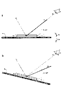
reference to Figures la to 2b. In Figure la there is shown, at least in
schematic form,
a cross-sectional view of an optical device 10 affixed to polymer substrate 9.
The
optical device 10 comprises a generally planar, laminate structure with two
layers
including a luminescent material layer 11 and optical filter layer 12.
Incident light 13,
which in this example comprises ultraviolet radiation, falls upon device 10
passing
through optical filter 12 to stimulate luminescent material 11. Once
stimulated,
luminescent material 11 is caused to emit luminescent radiation 14 comprising
electromagnetic radiation of a specific colour in the visible range at or
close to a
predetermined peak output wavelength. Since polymer substrate 9 is essentially
opaque, the luminescent radiation 14 primarily exits the device by passing
through
optical filter 12, the properties of which are preferably matched to receive
and
"process" only luminescent radiation at or close to the peak output wavelength
of
the luminescent radiation 14 emitted by luminescent material 11.
As a result, the luminescent radiation 14 is emitted from the device at or
very
close to a peak output angle theta, which in the example shown in Figure 1 is
about
45 degrees relative to the plane of substrate 9. This means that an eye 15 of
an
observer of the device, when positioned at 45 degrees relative to substrate 9
and
looking along line of sight 16, receives and can perceive or "see" the
luminescent
radiation 14 emitted from the device. In the example shown, however, the
optical
filter is very specific with regard to emission angle, so that most if not all
of
luminescent radiation 14 is emitted at or within 5 degrees of a peak output
angle.
Even slight tilting of the device by just a few degrees (see arrows 17a and
17b) results
in the luminescent radiation 14 no longer being visible to the observer's eye
15, via
line of sight 16.
16
CA 02932080 2016-06-03
For example, tilting of the same device relative to Figure la is indicated in
Figure 1b. Here substrate 9 and device 10 are both tilted "downwards" on the
right
side of Figure lb (compared to Figure la) as shown, in accordance with arrow
17b
(shown in Figure la), such that the angle theta of the line of sight 16
extending from
the observer's eye 15 is increased from 45 degrees to 60 degrees relative to
the
plane of substrate 9. All other aspects of Figure lb, including the incident
light 13
and the position of the observer's eye 15, remain unchanged over Figure la. It
may
be noted that luminescent radiation 14 no longer enters eye 15 along line of
sight 16,
and so will no longer be perceivable or visible to the observer. In fact, as
shown, the
same would be true had the device been tilted either "up" or "down" on the
right
side just a few degrees compared to Figure la. It will be apparent that if the
device is
tilted back from the position shown in Figure lb to the position shown in
Figure la,
and the user continuously and progressively tilts the device in the same
general
direction, luminescent radiation 14 will momentarily coincide with line of
sight 16 so
that the radiation will momentarily enter the user's eye 15 before the tilting
motion
of the device moves the luminescent radiation 14 back out of alignment with
line of
sight 16. The impression from the device, at least from the visual perspective
of the
user, thus will be a momentary "flash" of colour from the device as the device
is
tilted and the path of the luminescent radiation 14 momentarily passes through
line
of sight 16 as the device is progressively tilted "upwards" on the right side
(in
accordance with arrow 17a in Figure la). If a user stops tilting the device at
an angle
theta of 45 degrees, then the user will see the luminescent radiation
continuously
along line of sight 16, rather than a "flash".
Figures 2a and 2b illustrate graphs to show schematically how the
luminescent emission, and optical filtering of the emission, is affected as
the device
shown in Figure 1 is tilted relative to a user's eye. Figure 2a provides a
graph for a 45
degree viewing angle theta corresponding to Figure la, and Figure 2b provides
a
graph for a 60 degree viewing angle theta corresponding to Figure lb. In each
graph
the x-axis represents wavelength. The y-axis of each graph represents
intensity of
17
CA 02932080 2016-06-03
luminescence emission 14 from the luminescent material layer 11 (solid line)
as well
_
as the degree of transmission by the optical filter (dashed line). It is
notable that the
luminescent material 11 generates a luminescence emission 14 that (at least in
this
embodiment) is a single very narrow peak, corresponding to an intense single
colour
with a wavelength of about 475nm (blue). The optical filter has a transmission
specificity and generally blocks the transmission of electromagnetic
radiation, with
the exception of a narrow selection of wavelengths that are filtered and
refracted
though the filter. Importantly, the wavelength of electromagnetic radiation
that
transmits through the filter is dependent upon emission angle, such that the
filter
'permits' transmission of radiation at about 475nm to be emitted from the
filter at
about 45 degrees (Figure 2a), and further 'permits' transmission of radiation
at about
525nm to be emitted from the filter at about 60 degrees (Figure 2b). As shown
in
Figure 2a, at a 45 degree viewing angle the emission peak of the luminescent
radiation and the transmission / emission peak of the optical filter
effectively
coincide, permitting the user to 'see' the luminescence radiation at this
angle.
However, as shown in Figure 2b, at a 60 degree viewing angle the emission peak
of
the luminescent radiation and the transmission / emission peak of the optical
filter
do not coincide, and as a result the luminescence radiation is no longer
visible to a
user of the device at this viewing angle.
In effect, as shown in Figures 1 and 2, the optical filter coupled to the
luminescent material selectively transmits and emits the luminescent radiation
from
the device at a peak output angle, with the majority of the luminescent
radiation
produced by the luminescent material emitted from the device at, or close to,
the
peak output angle. The narrow emission peak and the narrow transmission peak
shown in Figures 2a and 2b, together with angle dependent emission of the
luminescent radiation, enable the luminescent radiation emanating from the
device
to be emitted as a very narrow band of emission at a specific emission angle.
This in
turn gives rise to the perceivable "flash" of the emitted radiation as the
device is
tilted continuously and progressively relative to the user's eye, which
contrasts
18
CA 02932080 2016-06-03
-
directly to other known colour-shift devices, which typically undergo a more
gradual
perceived colour shift or optical change during tilting.
Figures 3a and 3b illustrate an alternative embodiment. In most respects the
device 10a shown is in Figures 3a and 3b is identical to that shown in Figures
la and
lb (and the same 45 degree and 60 degree lines of sight 16 are illustrated in
Figures
3a and 3b respectively, between the user's eye 15 and the plane of substrate
9.
However, a key difference between the device in Figure 1 and the device in
Figure 3
relates to the optical filter 12. In Figure 3 an alternative optical filter
12a is used,
which has alternative optical properties to optical filter 12 shown in Figure
1, as will
be explained. These properties are such that optical filter 12a effectively
'splits' the
luminescent radiation 14 generated by stimulation of the luminescent material
11
between three distinct emission angles, illustrated in Figures 3a and 3b as
emitted
luminescent radiation 14a, 14b and 14c.
Therefore in Figures 3a and 3b, the same incident light 13 falls upon device
10a, passing through optical filter 12a to stimulate luminescent material 11,
which in
turn generates the same luminescent radiation 14 as for Figures la and lb.
However, upon subsequent transmission through optical filter 12a the
luminescent
radiation 14 is effectively divided into three distinct and narrow angles of
emission
14a, 14b and 14c, by virtue of the optical properties of the filter. In a
similar manner
to luminescent radiation 14 shown in Figure 1, the majority of the luminescent
radiation emanating from the device (from optical filter 12a) is emitted at,
or at least
very close to, each luminescent emission angle 14a, 14b, 14c, which represent
peak
angles of emission for the luminescent radiation emanating from the device.
Outside
of those peak emission angles, little or no luminescent emission occurs from
the
device. To a user of the device, the perceivable effect of this arrangement is
three
distinct "flashes" of luminescent radiation as the device is progressively
tilted, such
that each emission 14a, 14b, 14c momentarily intercepts line of sight 16.
In Figure 3a luminescent radiation 14a is in line with a 45 degree angle
between the plane of substrate 9 and line of sight 16, and thus luminescent
radiation
19
CA 02932080 2016-06-03
14a enters the user's eye 15. As the device is progressively tilted from the
position
illustrated in Figure 3a to the position illustrated in Figure 3b, the
luminescent
radiation will not generally enter the user's eye 15 until luminescent
radiation 14b is
in line with line of sight 16 as illustrated in Figure 31). Continued tilting
of the device
through and beyond the 60 degree angle shown in Figure 3b will result in
another
observable "flash" of radiation to user 15 attributable to luminescent
radiation 14b.
Again, as the angle further increases little or no luminescent radiation will
enter the
user's eye 15 until luminescent radiation 14c is in line with line of sight 16
(not
shown) at which time a third and final flash of luminescent radiation will be
observed
by the user as the device is progressively tilted to an angle of theta of more
than 75
degrees. In total, progressive tilting of the device from zero to ninety
degrees for
angle theta will cause three distinct "flashes" of radiation to be perceived
and
observed by the eye 15 of the user of the device as the device is tilted. As
described
previously, such "flashes" are not dynamic changes in the physical, chemical
or
.. optical properties of the device, but rather perceived as flashes by a user
of the
device as the emitted luminescent radiation intercepts the user's line of
sight.
Figures 4a and 4b illustrate graphs similar to those shown in Figures 2a and
2b. However, Figures 4a and 4b illustrate schematically the luminescent
radiation 14
of luminescent material 11, and the properties of alternative optical filter
12a. As for
Figures 2a and 2b, Figures 4a and 4b provide graphs for 45 degree and 60
viewing
angles for angle theta respectively. The graph showing luminescent emission 14
from
luminescent material 11 (solid line) retains an identical single peak output
wavelength as for Figures la and lb at 475nm, because the luminescent material
and
its luminescent properties are the same. Moreover, as for Figures 2a and 2b,
the
wavelength of the output radiation does not change with angle theta in Figures
4a
and 4b. However, in contrast to Figures 2a and 2b, the graph illustrated for
optical
filter transmission (dotted line) in Figures 4a and 4b includes not one but
three
distinct peaks, showing that the filter permits transmission and angle
dependent
CA 02932080 2016-06-03
-
emission of luminescent radiation at three different wavelengths for any given
viewing angle theta.
As for Figures la and 1b, by comparing Figures 4b to 4a it can be seen that an
increase in viewing angle theta effectively shifts the optical filter
transmission graph
(dotted line) to reposition the transmission peaks (at which the filter
permits
transmission of electromagnetic radiation) to higher wavelengths. For example,
Figure 4a illustrates both the luminescent radiation graph (solid line) and
optical filter
transmission graph (dotted line) for a given 45 degree viewing angle theta as
shown
in Figure 3a. The right hand peak in the graph for optical filter transmission
is aligned
at 475nm with the graph for luminescent radiation emission (solid line) for
the
luminescent material. As the viewing angle theta is increased from 45 degrees
to 60
degrees (as per Figure 3b) the graph for optical filter transmission
effectively shifts to
the right as shown in Figure 4b, and in doing so the middle peak in the graph
for
optical filter transmission (dotted line graph) is now positioned at 475nm in
line with
the peak luminescent radiation (solid line graph). Although not shown, a
further
increase in angle theta to 75 degrees would cause a still further shift to the
right for
the graph for optical filter transmission (dotted line), such that the left
hand peak in
the graph would be positioned at 475nm, in line with the peak luminescent
radiation
(solid line graph). In this way, the optical filter essentially 'permits'
transmission of
the luminescent light at 475nm to occur at or near to the peak output angles
of 45
degrees, 60 degrees, and 75 degrees for angle theta, corresponding to arrows
14a,
14b and 14c respectively in Figures 3a and 3b.
As for the embodiment described with reference to Figures 1 and 2, it may be
desired in some embodiments for most of the output of the luminescent
radiation to
have wavelengths at or close to the peak output wavelength, thereby to provide
a
relatively narrow peak for the graph of luminescence intensity (solid line in
Figures 4a
and 4b). Furthermore, it may be desired in some embodiments for the peaks in
the
optical filter transmission graph (dotted line in Figures 4a and 4b), which
define
wavelengths at which the optical filter permits transmission of light, to be
relatively
21
CA 02932080 2016-06-03
narrow. In this way, the large majority of the luminescent output of the
device is
focused into a narrow range of output angles, at or very close to the peak
output
angles corresponding to 14a, 14b, 14c shown in Figures 3a and 3b, which in
turn gives
rise to more sharply defined "flashes" of luminescent radiation perceived by a
user of
the device as the device is progressively tilted, and angle theta is increased
or
decreased.
For example, in some embodiments, the optical filter may be suitable to
cause at least 70 % of the luminescent radiation derived from the luminescent
material of the device to be emitted at, or within 15 degrees from, one or
more peak
output angles from the device, such that the luminescent radiation emitted
from the
device is momentarily observable or detectable at different peak output angles
as
the device is progressively tilted.
For example, in further embodiments, the optical filter may be suitable to
cause at least 80% of the luminescent radiation derived from the luminescent
material of the device to be emitted at, or within 10 degrees from, two or
more peak
output angles from the device, with fractions of the luminescent radiation
emitted
from the device momentarily observable or detectable at different output
angles as
the device is progressively tilted.
For example, in further embodiments, the optical filter may be suitable to
cause at least 90% of the luminescent radiation derived from the luminescent
material of the device to be emitted at, or within 5 degrees from, two or more
peak
output angles from the device, with fractions of the luminescent radiation
emitted
from the device momentarily observable or detectable at different output
angles as
the device is progressively tilted.
In other embodiments, the fractions of the luminescent radiation emitted
from the device (that are momentarily observable or detectable at different
output
angles as the device is progressively tilted) may depend in part upon the
nature of
the luminescent radiation generated by the luminescent material. For example,
in
some embodiments at least 70 percent of the luminescent radiation from the
22
CA 02932080 2016-06-03
luminescent material may have a wavelength at, or within 50nm of, a peak
output
wavelength. In other embodiments at least 80 percent of the luminescent
radiation
from the luminescent material may have a wavelength at, or within 25nm of, a
peak
output wavelength. In further embodiments at least 90 percent of the
luminescent
radiation from the luminescent material may have a wavelength at, or within
10nm
of, a peak output wavelength from the luminescent material. With increasing
degrees, therefore, the "narrowness" and intensity of the peak wavelengths of
luminescent radiation generated by the luminescent material (e.g. see graph
with
solid line in Figures 2a, 2b, 4a, 4b) can help define the observable flash or
flashes of
luminescent radiation as perceived from the perspective of the user. In other
examples, the luminescent material may emit luminescent radiation with a full
wave
half maximum (FWHM) of 50nm or less, 25nm or less, or 10nm or less depending
upon the embodiment, and the luminescent material being employed.
The graphs for optical filter transmission shown in Figures 4a and 4b (dotted
lines) each include three peaks corresponding to wavelengths at which the
optical
filter "permits" transmission of luminescent light therethrough, for any given
viewing
angle. As discussed, narrower transmission peaks correspond to more brief
"flashes"
of observable electromagnetic radiation as the device is progressively tilted
by a user.
In Figures 4a and 4b (and other figures) the transmission peaks (dotted lines)
are
shown to have a similar width and shape when compared to one another. For this
reason, progressive tilting of the device at a constant rate of tilt causes
three
corresponding flashes to be perceived by a user, with the flashes having
similar flash
durations. However, yet further embodiments include the use of alternative
optical
filters that exhibit optical transmission graphs with multiple peaks (in a
similar
manner to Figures 4a and 4b) but wherein the peaks have different widths
relative to
one another. Indeed, optical filters may be custom designed in this manner, as
required for any particular optical device. In this way, as the device is
progressively
tilted at a constant rate of tilt, the "flashes" of luminescent radiation that
are
apparent to the user may intercept the users line of sight for different time
periods.
23
CA 02932080 2016-06-03
. -
A longer "flash" typically corresponds to a wider range of angles of emission
of a
. _
particular portion or fraction of the luminescent radiation emanating from the
device, which in turn corresponds to a wider peak within the optical
transmission
graph for the optical filter. In contrast, a shorter "flash" typically
corresponds to a
narrower range of angles of emission for a particular portion or fraction of
the
luminescent radiation emanating from the device, which in turn corresponds to
a
narrower peak within the optical transmission graph for the optical filter.
Further
embodiments of the devices include optical filters that achieve different
length-of-
time flashes for one or more different wavelengths of luminescent radiation,
as the
devices are progressively tilted at a constant rate.
Any luminescent material may be used in accordance with the devices herein
disclosed. The luminescent material may be stimulated by any appropriate
source of
incident radiation suitable to cause the luminescent material to luminesce by
emission of electromagnetic radiation of a wavelength that is different to the
incident radiation. For example the luminescent material may be of a type that
is
stimulated to produce luminescent radiation in the visible spectrum subsequent
stimulation by incident ultraviolet light. This type of luminescent material
may
present certain advantages because the luminescent optical effect would be
observable only with the use of a screening device or tool that produces
incident UV
radiation, and yet the output would be visible to a user in the visible
spectrum.
Moreover, UV light sources are widely available and accepted technology for
document screening.
The optical filter used in accordance with the devices herein disclosed may
take any form or structure suitable to cause angle-dependent filtering of any
form of
luminescent radiation. More specifically, at least in selected embodiments,
the
optical filter may process the received luminescent radiation, so as to cause
the
luminescent radiation to be transmitted and emitted in an angle-dependent
manner
at or very close to one or more than one peak output angles. Such optical
filters, and
their optical transmission properties, may be custom-designed according to the
24
CA 02932080 2016-06-03
. -
nature of the luminescent radiation to be received and filtered, as well as
the type of
. .
angle and wavelength-dependent filtering required for the specific embodiment.
Optical filters may selected from, but are not limited to, optical
interference
structures such as a Fabry Perot structures, Bragg stacks, or thin-film
filters or foils.
Any optical filter may filter incident radiation upon the optical device and /
or
luminescent radiation emitted from the device. In some embodiments described
herein an optical filter is employed and described for angle dependent
filtering of
luminescent radiation emitted from luminescent material of the device.
However, in
other embodiments the optical filter may cause optical filtering, such as but
not
limited to angle dependent filtering, to the indicident radiation upon the
optical
device. Such optical filtering of incident radiation (before or without
stimulation of
the luminescent material) may provide further variants to the present optical
devices.
Any optical filter as described herein, for use with any corresponding optical
device, may have uniform optical filtering properties, and a substantially
uniform
form or structure, across an area of the filter. In some selected embodiments,
however, the optical filter may have non-uniform filtering properties, such
that
different optical filtering occurs for example in one area of the device
compared to
another. For example, the optical filtering properties may be dependent upon
the
thicknesses or optical properties of the layer or layers that make up the
optical filter.
If a spacer layer is required, such as for a Fabry Perot optical structure,
the thickness
of the spacer layer may vary progressively or markedly according to the region
of the
device, and a desired pattern of optical effects. Other foils may have
different
thicknesses or different optical densities in different regions or areas of
the device,
such that luminescent radiation is caused to be emitted from the device at
different
angles or degrees according to the optical filter. The devices as described
are not
limited with regard to the optical filters, and the manner in which they
influence
luminescent radiation in a uniform or non-unform manner.
CA 02932080 2016-06-03
Depending upon the device, the output of the luminescent material and the
transmission of the optical filter may be 'matched'. An optical filter may be
chosen
or designed, which specifically filters (in an angle-dependent manner)
radiation of a
wavelength corresponding to the peak output wavelength of the luminescent
radiation. For example, if the luminescent material is known to generate
luminescent radiation with a peak output wavelength of 460nm, then the optical
filter may be chosen or designed to transmit light selectively at between
440nm and
480nm at specific output angles.
Still further embodiments may comprise a luminescent material or layer that
when stimulated emits luminescent radiation of more than one wavelength. Such
luminescent materials may, for example, comprise two or more different
luminescent substances in admixture. Alternatively such luminescent materials
may
comprise discrete areas or layers of different luminescent substances that
appear to
luminesce at different wavelengths from different, the same, or overlapping
areas of
the device.
Such luminescent materials, when stimulated, may produce luminescent
radiation of more than one different peak output wavelength, for subsequent
angle-
dependent filtering by the optical filter. The optical filter in turn may
transmit and
emit luminescent radiations of different peak output wavelengths in the same
manner, such that they are emitted from the device at the same angles and in
the
same way. Alternatively, the luminescent radiation of one wavelength may be
emitted from the device at one or more peak output angles that are different
from
the peak output angles of luminescent radiation of at least one other
wavelength. In
this way, different fractions of the luminescent radiation with different
colours or
wavelengths may be emitted from the device at different angles such that they
are
observed by a user of the devices as "flashes" of different colours as the
device is
progressively tilted relative to the user / observer. Various embodiments
therefore
encompass devices that produce more than one wavelength of luminescent
26
CA 02932080 2016-06-03
radiation, wherein the associated optical filters are designed to separate and
/ or
blend the different colours produced at various output angles.
Therefore, in selected embodiments the devices may comprise more than one
type of luminescent material, each producing when stimulated luminescent
radiation
of a peak output wavelength that is different to the other types of
luminescent
material(s) present, so that the device produces luminescent radiation of more
than
one peak output wavelength. The optical filter then filters the resulting
luminescent
radiation in a angle-dependent manner, the luminescent radiation of one
wavelength
being emitted from the device at one or more peak output angles that are the
same
or different from the peak output angles of luminescent radiation of at least
one
other wavelength. In this way, different fractions of the luminescent
radiation
emitted from the device with different colours or wavelengths may be
momentarily
observable or detectable as the device is progressively tilted.
Figures 5a, 5b, and 5c illustrate an exemplary embodiment of a device 10a
that employs a luminescent material 11a that, by virtue of a blend of
luminescent
substances present, produces when stimulated combined luminescent radiations
with three different peak output wavelengths or colours at 550nm, 580nm and
605nm (or green, yellow and orange respectively). Depending upon the structure
or
configuration of the luminescent material, the different colours may be
emitted from
the same or different areas of the device as required.
Therefore, as shown in Figures 5a to 5c, the same incident light 13 falls upon
device 10a, passing through optical filter 12a to stimulate luminescent
material 11a,
which in turn luminesces to generate luminescent radiation of three different
colours: green, yellow and orange. Optical filter 12a filters the luminescent
radiation
.. of three different colours permitting emission of each colour from the
device in
angle-dependent manner. In Figure 5a it can be seen that green luminescent
radiation is emitted as arrows 140a and 140b, yellow luminescent radiation is
emitted as arrows 150a and 150b, and orange luminescent radiation is emitted
as
arrows 160a and 160b, from the device. As before, each luminescent radiation
of
27
CA 02932080 2016-06-03
..
140a, 140b, 150a, 150b, 160a and 160b represents luminescent radiation emitted
. .
from device 10a at or close to specific peak emission angles. As a result,
progressive
tilting of the device by a user will result in perception of multiple flashes
of different
colours of luminescent radiation from the device.
In Figure 5a an angle theta of 45 degrees from the line of sight 16 (from
eye 15) to a plane of the substrate 9 causes eye 15 to see green fluorescent
emission
140a from the device. In Figure 5b the device has been progressively tilted
(as per
arrow 17b in Figure 5a) such that angle theta has increased from 45 to 60
degrees. In
doing so the user will see a brief flash of yellow as yellow fluorescent
emission 150a
passes though the line of sight 16 before angle theta reaches 60 degrees as
shown in
Figure 5b, at which moment a user will see orange luminescent radiation 160a
along
line of sight 16. In Figure 5c the device has been progressively tilted yet
further (as
per arrow 17b in Figure 5a) such that angle theta has further increased from
60 to 75
degrees. In doing so the user sees a brief flash of green as green fluorescent
emission 140b passes though the line of sight 16 before angle theta reaches 75
degrees as shown in Figure 5c, at which moment a user will see yellow
luminescent
radiation 150b along line of sight 16. So it may be seen that a user
progressively
tilting device 10a, such that angle theta increases from zero to ninety
degrees will
observe momentary flashes of emitted luminescent radiation from the device
that
are green, yellow, orange, green, yellow and again orange. If a user stops
tilting the
device at any angle that corresponds to emission 140a, 140b, 140c, 150a, 150b,
150c,
160a, 160b or 160c then the user will see a corresponding steady or continuous
emission colour along line of sight 16.
In a manner similar to previous figures, Figures 6a, 6b and 6c provide a
graphical representation of Figures 5a, 5b and Sc respectively. In each of
Figures 6a,
6b and 6c three peaks of luminescence intensity are shown for the luminescent
radiation 140, 150, 160 shown in Figure 5. The left hand peak is labeled
"green"
(arrows 140 shown in Figure 5), the middle peak is labeled "yellow" (arrows
150 in
Figure 5), and the right hand peak is labeled "orange" (arrows 160 in Figure
5). As
28
CA 02932080 2016-06-03
before, the graph for optical transmission by optical filter 12a is shown as a
dotted
line, which in this embodiment includes two "peaks" indicative of increased
transmission at specific wavelengths, wherein the optical filter essentially
"permits"
transmission of light therethrough for any given angle theta. The two peaks
essentially cause each colour of the luminescence radiation 140, 150 and 160
to be
split into luminescent radiation emergent from the device at two different
angles for
each wavelength, corresponding to 140a and 140b, or 150a and 150b, or 160a and
160b, respectively.
In Figure 6a, which corresponds to an angle theta of 45 degrees as per Figure
5a, the right hand peak in the graph for optical filter transmission is in
alignment with
the peak for green luminescence such that a user's eye 15 views the green
emission
140a along line of sight 16 in Figure 5a. As the device is tilted along arrow
17b
(shown in Figure 5a) the optical filter transmission graph essentially shifts
to the
right, such that with increasing angles of theta the optical filter permits
transmission
therethrough of increasingly higher wavelengths of radiation. Therefore, as
shown in
Figure 6b, with an angle theta of 60 degrees the right hand peak in the graph
for
optical filter transmission (dotted line) is in alignment with the peak for
orange
luminescent radiation, such that user 15 can look along line of sight 16 and
view
orange luminescent radiation 160a (see Figure 5b). Further, as shown in Figure
6c,
with an angle theta of 75 degrees the left hand peak in the graph for optical
filter
transmission is in alignment with the peak for yellow luminescent radiation,
such that
user 15 can look along line of sight 16 and view yellow luminescent radiation
150b
(see Figure 5c).
In yet further embodiments, a device may be produced that presents
different luminescent images to a user of the device depending upon the angle
theta
at which the device is held by the user. For example, in Figure 7a there is
shown a
device that, for a first angle theta, a dollar sign is observed having a
luminescent
wavelength of 525nm (blue). However, Figure 7b shows the same device as Figure
7a
but when observed at a second angle theta that is different from the first
angle theta,
29
CA 02932080 2016-06-03
._
such that the dollar sign is no longer observable at the particular viewing
angle, and
. _
instead a number "20" is observed having a luminescent wavelength of 675nm
(red).
As illustrated, the number "20" is located in the same area or at an
overlapping
position of the device compared to the blue dollar sign. However, in other
embodiments the different images may be located at the same, a different or
overlapping locations or areas of the device. In select embodiments, the
optical filter
may be such that at some angles theta the blue and red images may be emitted
together at the same angle thus giving a blended image as shown in Figure 7c,
In yet further embodiments, the devices may include more complex
arrangements of luminescent materials and more complex filters, such that
perceived moving images are possible as the user progressively tilts the
device from a
first angle theta to a second angle theta, wherein the moving images may
comprise
multiple different images viewed at different angles optionally using
different
wavelengths of fluorescence emission from the device.
The embodiments thus far have described and explained devices that, at least
from the perception of a user progressively tilting the device, exhibit brief
"flashes"
of luminescent radiation corresponding to the interception of narrow bands of
radiation emitted from the device at specific angles momentarily within the
user's
line of sight, Such devices may be collectively termed "flash-on" devices
because at
most emission angles theta they appear to a user to be primarily "dark" in
that no
emitted radiation can be observed by a user, and yet as they are progressively
tilted
brief "flashes" of emitted radiation are observed. In still further
contrasting
embodiments, "flash-off' devices may also be generated, in which a user can
detect
or see emitted luminescent radiation at most emission angles theta, and yet at
specific angles theta the device does not appear, at least from the
perspective of the
user, to emit any luminescent radiation. In other words, an opposite effect to
the
previously described embodiments may be achieved, in which brief "flashes off"
are
observed as the device is progressively tilted.
CA 02932080 2016-06-03
An example "flash off" device is described with reference to Figures 8a and
8b. In Figure 8a the device 10c is shown in cross section upon substrate 9,
with
luminescent material 11 and optical filter 12c. Incident radiation 13
stimulates
luminescent material 11, which generates luminescent radiation. This
luminescent
.. radiation is filtered by optical filter 12c in an angle-dependent manner,
but rather
than being emitted from the device in one or more narrow bands of emitted
radiation as before, the optical filter is such that the luminescent radiation
is emitted
at all angles 200 with two notable exceptions for dark angles 210a and 210b
(Figure
8a also shows the additional fluorescent emission from the device as a
'mirror' of
emission from the normal from the device, with corresponding dark angles 210a'
and
210b'; see below). When the angle theta is increased by progressively tilting
the
device in direction 17b the user's eye 15 can detect luminescent radiation 200
at
most angles theta, except for when angle theta is such that line of sight 16
co-incides
or aligns with dark angles 210a and 210b: at these viewing angles the device
(at least
from the perception of the user) appears to "flash-off" briefly before the
user once
again sees or detects luminescent radiation 200 at a further increased angle
of theta
as the device is progressively tilted relative to the user. If a user stops
tilting the
device at either of dark angles 210a and 210b, then the user will continuously
see
little or no luminescent radiation along line of sight 16.
Figure 8b graphically illustrates the luminescent radiation and optical
filtering
of the device illustrated in Figure 8a. It may be seen that the device
generates
luminescent radiation of just one wavelength (solid line) at 600nm. The
optical filter
transmission, (dotted line) is such that the optical filter transmits the
luminescent
radiation at most angles theta, except for two specific angles theta
corresponding to
dark angles 210a and 210b in Figure 8a. As angle theta progressively increases
(not
shown) the two narrow troughs of the graph for optical filter transmission
(dotted
line) briefly align themselves with the peak luminescence intensity for the
luminescent radiation, giving rise to two perceived "flashes-off' as the
device is
progressively tilted.
31
CA 02932080 2016-06-03
For greater certainty, the described optical properties and perceived visual
appearance of any optical device described herein may relate to the entirety
of the
device, or alternatively may relate to any portion of the device at any given
time or
viewing angle. For example, in relation to the "flash-off" devices described
above,
.. depending upon the size and situation of the optical device (including the
nature of
incident light), only a portion of the device may appear to "flash-off" as the
device is
tilted, whilst other options of the device may continue to appear to emit
luminescent
radiation. As the device is tilted, the portions of the device that appear to
"flash-off"
may change according to viewing angle. For example, as the device is tilted a
dark
region or stripe may appear to 'scroll' across the device, wherein the viewing
angle of
the dark portions of the device coinciding with an emission angle at which the
luminescent radiation is essentially blocked by the optical filter. Likewise,
for "flash-
on" devices, the portions of the device that appear to "flash-on" may also
vary with
viewing angle such that a flash of colour or luminescent radiation may appear
to
.. move or scroll across the device as the device is progressively tilted.
In yet further embodiments, a device may include both flash-on and flash-off
properties in combination, wherein the flash-on and flash-off may or may not
overlap. For example, a device may comprise a luminescent material that
generates
two wavelengths of luminescent radiation (e.g. red and green). The green
radiation
may be filtered in a flash-on manner, such that brief flashes of green
luminescent
radiation are observable to a user as the device is progressively tilted.
Simultaneously, the red luminescent radiation may be filtered in a flash-off
manner,
such that for each angle theta, when the green luminescent radiation is
visible, the
red luminescent radiation is not visible to a user, and when the red
luminescent
radiation is visible to a user, the green luminescent radiation is not
visible. As this
device is progressively tilted it will appear to luminesce predominantly red,
and the
red will appear from the user's perspective to be replaced briefly with green
only at
specific angles of theta.
32
CA 02932080 2016-06-03
...
In further embodiments there is provided a use of any optical device disclosed
. .
herein, to provide authentication to a security item or document. The optical
device
may be secured, integrated or adhered to the substrate of the security item or
document in any way. In select embodiments, the security document may be a
banknote, the optical device providing authentication as a security feature to
the
bank note.
Therefore, in further exemplary embodiments there is provided a security
item or document, comprising a substrate with any optical device as herein
described
affixed, integrated or adhered thereto. In select embodiments, the security
document may be a banknote, the optical device providing an authentication or
security feature to the bank note.
Further exemplary embodiments also provide a method for determining
whether a security device or document is a legitimate or counterfeit device or
document, the item or document comprising any optical device as herein
described,
the method comprising the steps of: illuminating the optical device with
radiation of
a wavelength suitable to stimulate the luminescent material or materials
present;
progressively tilting the item or document whilst the device emits luminescent
radiation; and observing or detecting at least one fraction of said
luminescent
radiation emitted from the device. The step of progressive tilting may be
performed
manually, or with the assistance of a screening tool that may, for example,
also
provide the source of incident radiation for stimulation of the luminescent
material.
Further, in certain exemplary embodiments a predetermined pattern of detected
(by
a detection device) or observed (by a user inspecting the device) fractions of
luminescent radiation as the device is progressively tilted is indicative that
the device
is legitimate and not counterfeit.
In alternative exemplary methods, a plurality of sensors is used obviating the
need for tilting of the optical device. For example, other exemplary
embodiments
provide a method for determining whether a security device or document is a
legitimate or counterfeit device or document, the item or document comprising
any
33
CA 02932080 2016-06-03
...
optical device as described herein, the method comprising the steps of:
illuminating
. _
the optical device with radiation of a wavelength suitable to stimulate the
luminescent material or materials present; positioning a plurality of sensors
at a
plurality of positions or angles relative to the optical device whilst the
optical device
emits luminescent radiation; and detecting with said sensors at least one
fraction of
said luminescent radiation emitted from the optical device. Such methods may
further comprise one or more of the following optional steps: calculating and
optionally displaying the detected output angles for the luminescent radiation
from
the device, and optionally comparing the detected output angles with
predetermined
output angles known to correlate with legitimate or non-counterfeit optical
devices.
Such methods may be useful, for example, in bank note sorting machines in
which
banknotes are rapidly checked for authentication, either whilst the banknotes
are
stationary or moving through the sorting machine.
Other exemplary embodiments provide for a method for improving the
security of an item or document, to help prevent counterfeit thereof, the
method
comprising: adhering or affixing any optical device as herein described to the
item or
document. In certain such embodiments the item or document is a banknote.
In still further exemplary embodiments there is provided an authentication
device, to test whether an item or document (that appears to comprise any
optical
device as described herein) is legitimate or counterfeit, the authentication
device
comprising:
optionally a holder to hold the item or document being tested;
a source of electromagnetic radiation suitable to stimulate the luminescent
material of the optical device; and
one or more sensors to gather information regarding angles of emission of
luminescent radiation from the device;
optionally movement means to move the one or more sensors and the item
or document relative to one another, to enable the one or more sensors to
scan for different angles of emission of luminescent radiation from the
device;
34
CA 02932080 2016-06-03
-
a comparison component to compare sensed angles of emission of
. ,
luminescent radiation from the optical device with predetermined angles of
emission known to be indicative of an authentic optical device, and therefore
indicative an authentic item or document comprising the optical device.
Optionally the authentication device may further comprise an output
component to provide a visual or electronic signal indicative of whether the
item or
document comprising the optical device is authentic or counterfeit.
Optionally, the authentication device may comprise a plurality of sensors,
each to detect luminescent radiation emitted at a different emission angles
from the
device so that the plurality of sensors gather information regarding angles of
emission of luminescent radiation from the device without necessarily needing
to
move the sensors and the item or document relative to one another.
Whilst the figures illustrate schematically various light paths and beams by
way of certain arrows of both incident and emitted radiation, the embodiments
illustrated are schematic and are not limited in this regard. For example,
depending
upon the optical filter, the emitted luminescent radiation illustrated at a
certain
angle theta may occur at all angles of theta from the plane of the device, and
not just
from the angle theta shown in the cross-sectional illustration of the device.
In other
words, emitted luminescent radiation shown by a single arrow in a figure may
in fact
occur, at least in selected embodiments, as a "cone" of radiation having an
axis of
symmetry corresponding to the normal of the device (the normal being a 90
degree
angle of theta from a plane of the device). Therefore, the cross-sectional
views of
the device could also illustrate additional beams or paths of luminescent
radiation,
identical to those shown but mirrored from the normal (90 degree angle of
theta).
For selected illustrations, these additional beams or paths have been omitted
for
ease and simplicity of illustration and explanation. One exception is Figure
8a, in
which luminescent emission symmetry is shown about the normal from the device.
CA 02932080 2016-06-03
Whilst various embodiments are disclosed and explained herein they are
exemplary and merely illustrative. Further embodiments not specifically
described
are intended to be encompassed within the scope of the present disclosure. The
embodiments disclosed and explained herein are thus in no way intended to
limit the
scope of the appended claims.
36