Note: Descriptions are shown in the official language in which they were submitted.
81797235
MATERIAL HANDLING VEHICLE WITH
PRODUCT PLACEMENT INDICATION
[0001]
STATEMENT CONCERNING FEDERALLY SPONSORED
RESEARCH OR DEVELOPMENT
[0002] Not applicable.
FIELD OF THE INVENTION
[0003] The present invention relates to the field of material handling
vehicles, and more specifically to material handling vehicle that provides a
visual indication for a product placement.
BACKGROUND OF THE INVENTION
[0004] Material handling vehicles are designed in a variety of
configurations to perform a variety of tasks. These types of vehicles are
commonly used in a warehouse or a factory to transport, store, and
retrieve materials and finished goods.
[0005] Material handling vehicles are used to temporarily hold and
transport products picked from shelves by an order picker to fill a
customer order. The products are typically stored on shelves in a rack
system in which a plurality of unit loads of many products are stored.
Each unit load, generally, contains a single type of product, and a
customer typically requires one or more boxes of product picked from
many different unit loads. This requires the order picker to travel up and
down one or more aisles of the rack system to
1
Date Recue/Date Received 2021-07-12
CA 02932445 2016-06-01
WO 2015/116642 PCT/1JS2015/013224
pick products from many different locations in the rack system to fill the
customer's order. Typically, each product picked by the operator is placed on
a
load platform on the vehicle.
[0006] In some applications, the load platform on the vehicle includes
more than one predefined placement location for picked products. Each
predefined placement location can be used for a specific customer, and the
specific customer's picked goods are placed on the platform in the specific
customer's predefined placement location.
[0007] The vehicle used in this type of application is commonly referred to
as an order picker truck. The order picker truck can include a load platform,
typically a set of forks, that are sized sufficiently long so two or more
pallets
can be placed on the forks or held by the forks generally side-by-side along
the
length of the forks. The order picker receives instructions that indicate what
product to pick for a specific customer, and what pallet to place the product
on, for the specific customer.
[0008] The instructions to the order picker are either written, e.g., on a
pick sheet or on a display screen on the vehicle, or are audio, e.g., the
operator
can wear a hands-free headset controlled by a warehouse management system
that can provide an audio instruction. Both of these forms of instruction
require the order picker to remember what specific predefined placement
location is for a specific customer.
[0009] With two or more predefined placement locations on the load
platform, it is easy for the order picker to mistake one placement location
for
any of the others, or to forget which predefined placement location
corresponds
to the written or audio indication.
[0010] In an order picking application, the result of putting the product
in
the wrong placement location is twofold. The customer that did not order the
product, but received it anyway, will most likely keep the product that they
did
not pay for. Then, the customer that did order the product, but did not get
the
product with their order, may be dissatisfied and request a fast turnaround on
-2-
CA 02932445 2016-06-01
WO 2015/116642 PCMJS2015/013224
correctly completing the order. In some cases, future business with the
customer may be affected.
[0011] Another option has been to put picked product for the same
customer on all of the predefined placement locations on the load platform,
i.e.,
one vehicle for one customer. This reduces the errors created by placing the
product in the wrong placement location, but it also reduces productivity. The
order picker spends more time traveling from pick location to pick location
and
this travel time is not productive.
[0012] What is needed is an indication system that solves the problems
associated with providing instructions to an order picker.
SUMMARY OF THE INVENTION
[0013] Embodiments of the present invention overcome the drawbacks of
previous systems and methods by providing one or more visual indicators that
indicate the predefined placement location on the load platform where the
product is to be placed. When the order picker picks a product to be placed
onto the load platform, a visual indicator can indicate on, at, or near which
predefined placement location the order picker is to place the picked product.
The visual indication serves as a visual confirmation for the order picker to
place a product in a specific predefined placement location for a specific
customer delivery/ shipment. An advantage of this technology compared to
prior methods is increased productivity without increased error.
[0014] In accordance with one embodiment of the invention, a visual
indication system is disclosed. The system comprises a material handling
vehicle, the material handling vehicle including at least a first product
placement location on a load platform and a second product placement location
on the load platform; and at least one visual indicator, the at least one
visual
indicator to provide a visual indication on, at, or near the at least the
first
product placement location and the second product placement location.
[0015] In accordance with another embodiment of the invention, a visual
indication system is disclosed. The system is for use on a material handling
-3-
81797235
vehicle, the material handling vehicle including at least a first product
placement location on a load platfoini and a second product placement
location on the load platform, the second product placement area being
different than the first product placement area, the load platform
including at least a first aperture and a second aperture. The system
comprises at least a first visual indicator and a second visual indicator,
the at least the first visual indicator and the second visual indicator to be
coupled to the load platfoi ________________________________________ in, the
at least the first visual indicator to
provide a first visual indication on, at, or near the first product placement
location and the second visual indicator to provide a second visual
indication on, at, or near the second product placement location; and the
at least the first visual indicator to provide the first visual indication
through the first aperture, and the second visual indicator to provide the
second visual indication through the second aperture.
[0016] In
accordance with another embodiment of the invention, a
method is disclosed. The method comprises instructing a visual indicator
on a material handling vehicle to provide a visual indication to be visible
on, at, or near a first specific placement location on a load platform of the
material handling vehicle or a second specific placement location on the
load platform of the material handling vehicle, the second product
placement area being different than the first product placement area.
[0017] It is to
be appreciated that any of the various features
described herein can be combined with some or all of the other features
described herein according to alternate embodiments.
[0018] The
foregoing advantages of the invention will appear in the
detailed description which follows. In the description, reference is made to
the accompanying drawings which illustrate preferred embodiments.
[0018a] In
accordance with yet another embodiment of the invention,
there is provided a visual indication system comprising: a material
handling vehicle including a base unit and a load platform mounted
relative to the base unit, the load platfoini including at least one fork
being vertically moveable between an upper position and a lower position;
4
Date Recue/Date Received 2021-07-12
81797235
and at least a first product placement location on the at least one fork and
a second product placement location on the at least one fork; at least one
visual indicator, the at least one visual indicator to provide a visual
indication on, at, or near the at least the first product placement location
and the second product placement location, and wherein the at least one
visual indicator projects an illumination on, at, or near the load platform
to visually identify with the projected illumination one of the at least the
first product placement location and the second product placement
location.
[0018b] In
accordance with yet another embodiment of the invention,
there is provided a visual indication system for use on a material handling
vehicle, the material handling vehicle including a base unit and a load
platform mounted relative to the base unit, the load platform being
vertically moveable between an upper position and a lower position, the
material handling vehicle including at least a first product placement
location on the load platform and a second product placement location on
the load platform, the second product placement location being different
than the first product placement location, the load platfoi ________ in
including at
least a first aperture and a second aperture, the system comprising: at
least a first visual indicator and a second visual indicator, the at least the
first visual indicator and the second visual indicator to be coupled to the
load platfoi _______________________________________________________ in, the
at least the first visual indicator to provide a first visual
indication on, at, or near the first product placement location and the
second visual indicator to provide a second visual indication on, at, or
near the second product placement location; and the at least the first
visual indicator to provide the first visual indication through the first
aperture, and the second visual indicator to provide the second visual
indication through the second aperture.
[0018c] In
accordance with yet another embodiment of the invention,
there is provided a method comprising: receiving a wireless signal from a
remote device; and based on the wireless signal, providing a signal to a
first visual indicator on a material handling vehicle to cause the visual
4a
Date Recue/Date Received 2021-07-12
81797235
indicator to provide a visual indication to be visible on, at, or near a first
placement location on a load platform of the material handling vehicle or a
second placement location on the load platform of the material handling
vehicle, the second placement location being different than the first
placement location, and wherein the material handling vehicle includes a
base unit, wherein the load platform is mounted relative to the base unit,
and the load platform is vertically moveable between an upper position
and a lower position.
BRIEF DESCRIPTION OF THE DRAWINGS
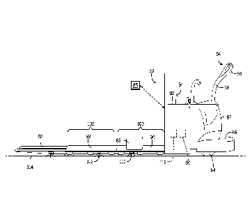
[0019] FIG. 1 is
a perspective view of a material handling vehicle that
has components operable to provide visual indication to an order picker in
accordance with embodiments of the present invention;
4b
Date Recue/Date Received 2021-07-12
CA 02932445 2016-06-01
WO 2015/116642 PCMJS2015/013224
[0020] FIGs. 2 and 3 are cross-section views of embodiments of brackets
mounted to a load platform, with the bracket supporting a visual indicator, in
accordance with embodiments of the present invention;
[0021] FIG. 4 is a cross-section view of a load platform, with the load
platform supporting a visual indicator, in accordance with embodiments of the
present invention;
[0022] FIG. 5 is a side view of a material handling vehicle similar to
FIG. 1
and showing a load platform with three apertures usable with visual
indicators,
in accordance with embodiments of the present invention;
[0023] FIG. 6 is a perspective view of an alternative visual indication
system usable with the material handling vehicle of FIG. 1, in accordance with
embodiments of the present invention; and
[0024] FIG. 7 is a perspective view of an additional alternative visual
indication system usable with the material handling vehicle of FIG. 1, in
accordance with embodiments of the present invention.
[0025] The invention may be embodied in several forms without departing
from its spirit or essential characteristics. The scope of the invention is
defined
in the appended claims, rather than in the specific description preceding
them.
All embodiments that fall within the meaning and range of equivalency of the
claims are therefore intended to be embraced by the claims.
DETAILED DESCRIPTION OF THE PREFERRED EMBODIMENT
[0026] The invention will now be described more specifically with
reference to the following embodiments. It is to be noted that the following
embodiments are presented herein for purpose of illustration and description
only. It is not intended to be exhaustive or to be limited to the precise form
disclosed.
[0027] It is to be understood that the phraseology and terminology used
herein is for the purpose of description and should not be regarded as
limiting.
The use of "including," "comprising," or "having" and variations thereof
herein
-5-
CA 02932445 2016-06-01
WO 2015/116642 PCT/US2015/013224
is meant to encompass the items listed thereafter and equivalents thereof as
well as additional items.
[0028] Unless specified or limited otherwise, the terms "connected" and
"coupled" and variations thereof are used broadly and encompass both direct
and indirect mountings, connections, supports, and couplings. Further,
"connected" and "coupled" are not restricted to physical or mechanical
connections or couplings. As used herein, unless expressly stated otherwise,
"connected" means that one element/feature is directly or indirectly connected
to another element/feature, and not necessarily electrically or mechanically.
Likewise, unless expressly stated otherwise, "coupled" means that one
element/feature is directly or indirectly coupled to another element/feature,
and not necessarily electrically or mechanically. Thus, although schematics
shown in the figures depict example arrangements of processing elements,
additional intervening elements, devices, features, or components may be
present in an actual embodiment.
[0029] As used herein, the terms "component," "system," "device" and the
like are intended to refer to either hardware, a combination of hardware and
software, software, or software in execution. The word "exemplary" is used
herein to mean serving as an example, instance, or illustration. Any aspect or
design described herein as "exemplary" is not necessarily to be construed as
preferred or advantageous over other aspects or designs.
[0030] Furthermore, the disclosed subject matter may be implemented as
a system, method, apparatus, or article of manufacture using standard
programming and/or engineering techniques and/or programming to produce
hardware, firmware, software, or any combination thereof to implement aspects
detailed herein.
[0031] As used herein, the terms "processor" and "controller" may include
one or more processors and memories and/or one or more programmable
hardware elements. As used herein, the terms "processor" and "controller" are
intended to include any types of processors, CPUs, microcontrollers, digital
signal processors, or other devices capable of executing software
instructions.
-6-
CA 02932445 2016-06-01
WO 2015/116642 PCMJS2015/013224
[0032] As used herein, the term "memory" includes a non-volatile
medium, e.g., a magnetic media or hard disk, optical storage, or flash memory;
a volatile medium, such as system memory, e.g., random access memory (RAM)
such as DRAM, SRAM, EDO RAM, RAMBUS RAM, DR DRAM, etc.; or an
installation medium, such as software media, e.g., a CD-ROM, or floppy disks,
on which configuration data and programs may be stored and/or data
communications may be buffered. The term "memory" may also include other
types of known or future developed memory or combinations thereof.
[0033] The various aspects of the invention will be described in
connection with visual indicators that visually indicate on, at, or near a
specific
predefined placement location on the load platform where the selected product
is to be placed. That is because the features and advantages that arise due to
embodiments of the invention are well suited to this purpose. Still, it should
be
appreciated that the various aspects of the invention can be applied to other
vehicles and to achieve other objectives as well.
[0034] It is to be appreciated that material handling vehicles are designed
in a variety of configurations to perform a variety of tasks. Although the
vehicle
50 is shown by way of example as a hand/rider truck, it will be apparent to
those of skill in the art that the embodiments are not limited to vehicles of
this
type, and can also be provided with various other types of vehicle
configurations, including for example, vans, semi trucks, pickup trucks,
pallet
trucks, stacker trucks, fore-aft stance operator lift trucks, reach trucks,
high-
lift trucks, counterbalanced trucks, and swing-reach trucks, as non-limiting
examples. The systems and methods described herein are suitable for both
driver controlled, pedestrian controlled and remotely controlled material
handling vehicles, along with non-motorized carts or load platforms that are
manually pushed by an order picker.
[0035] Referring now to the Figures, and more particularly to FIG. 1, one
embodiment of a material handling vehicle 50 that incorporates the present
invention is shown. A hand/rider order picking vehicle 50 is depicted having a
load platform 52 that can be vertically movable between a lower position and
-7-
81797235
an upper position. Typically, the load platform 52 would comprise load
bearing forks, although not required. The vehicle 50 also includes a
steering control mechanism 54 that can include a movable steering
arm 56 and steering arm handle 60. The vehicle 50 is also provided with a
motor housing 62 and a steerable drive tire 64 located under a
platform 66.
[0036] The vehicle 50 can also include a vehicle controller 80 that
receives operator input signals and, based on the received signals,
provides command signals to each of a lift motor (not shown) and a drive
system (not shown) that includes the drive tire 64. The vehicle 50 and
vehicle controller 80 can be powered by one or more battery(s) 82 to
provide motive and control power.
[0037] In some embodiments, an antenna 84 for wireless
communications with a known external warehouse management
system 86 can be coupled to the vehicle 50 and in some embodiments can
be connected to the vehicle controller 80 to provide bidirectional
communications from the vehicle 50 to the warehouse management
system. The communications link may be implemented by a connection
through the Internet, a Wi-FiTM system, or various other known wireless
links.
[0038] The warehouse management system 86 can comprise
software that is executed on a computer and operable to communicate
with the vehicle 50. By providing simple connections and a standard
protocol, systems and methods of the present technology are adaptable for
use with a number of different warehousing systems.
[0039] In the exemplary vehicle shown, the load platfoim 52 can be
sized such that one or more pallets can be placed on the load platform 52
in a known fashion. It is to be appreciated that any known pallet types
may be used. In this example, a first pallet 90 and a second pallet 92 are
shown on the load platfoim 52. The first pallet 90 represents a predefined
placement location, e.g., a first product placement location 100, and the
second pallet 92 represents another predefined placement location, e.g., a
8
Date Recue/Date Received 2021-07-12
81797235
second product placement location 102. It is to be appreciated that the
first pallet 90 and the second pallet 92 are not required. The load
platform 52 can be any
8a
Date Recue/Date Received 2021-07-12
CA 02932445 2016-06-01
WO 2015/116642 PCT/1JS2015/013224
configuration able to support the placement of picked products. In addition,
more than two specific pallet or placement locations are possible, or a
combination of pallet and placement locations.
[0040] In the context of this example, the vehicle operator will also be
considered the order picker. The order picker will pick a product, for example
off of a shelf, and place the picked product 88 on one of the first pallet 90
or
the second pallet 92 (shown placed on the first pallet 90). It is to be
appreciated
that the order picker does not need to be the vehicle operator. The technology
allows anyone who picks a product to more accurately place the product in a
specific placement location.
[0041] In one embodiment, the vehicle 50 can include a first visual
indicator 110 located on, at, or near the first product placement location 100
and a second visual indicator 112 located on, at, or near the second product
placement location 102. The position of the first visual indicator 110 and the
second visual indicator 112 can be adjustable to accommodate variations in
size or shape or position of the first product placement location 100 and the
second product placement location 102. In some embodiments, the visual
indicators 110 and/or 112 can comprise an LED or an incandescent bulb, or a
laser, as non-limiting examples, to provide illumination. In the embodiments
shown, the visual indicator 110 can project illumination onto the floor 114 at
or near the first product placement location 100, and the visual indicator 112
can project illumination onto the floor 114 at or near the second product
placement location 102. It is to be appreciated that the visual indicators 110
and 112 can project illumination in any desired direction or location on the
vehicle or on the floor, or both, that would be visible by the order picker,
including away from the floor and parallel to the floor, for example, so that
the
order picker can see which product placement location is indicated. In this
context, near is intended to indicate within a range that the order picker
would
understand the indication was specific to one product placement location and
not another specific product placement location.
-9-
CA 02932445 2016-06-01
WO 2015/116642 PCMJS2015/013224
[0042] Referring to FIGS. 2 and 3, in some embodiments, the visual
indicators 110 and 112 can be coupled to the load platform 52. As seen in the
cross-sectional view of FIG. 2, in one embodiment, visual indicator 110
comprises a bracket 128 coupled to the load platform 52. Although visual
indicator 110 is shown and described, it is to be appreciated that multiple
visual indicators 110, 112, or more (as would be used in FIG. 5) could be
used.
A single bracket 128 can be used that includes visual indicators 110, 112 for
example, or two brackets 128 could be used, one for visual indicator 110 and
one for visual indicator 112. It is to be appreciated that the bracket 128 can
be
coupled to the load platform 52 in a variety of ways, including bolts,
welding, or
magnetic, as non-limiting examples. The bracket 128 may be removably
coupled to the load platform 52 to allow the visual indicator 110 to be
repositioned along the load platform to a desired position. Within the bracket
128, a circuit board 132 can be positioned that includes one or more LEDs 134
(three LEDs are shown). The circuit board 132 and LEDs 134 can be positioned
within the bracket 128 to project illumination through aperture 138 so the
illumination shines on the ground 114, or elsewhere, as described above.
Control wiring 142 can extend from the circuit board 132 through the bracket
or through the load platform 52, or both, back to the controller 80 or visual
indicator controller 116 discussed in greater detail below. The visual
indicator
110 can also be a wireless device, discussed in greater detail below. A
mounting plate, glue, or clips, for example, (not shown) can also be used to
position the circuit board 132 in the bracket 128.
[0043] In some embodiments, a shield 144 can be positioned over the
aperture 138 to provide protection for the LEDs/circuit board. The shield 144
can be a thermoplastic polymer material for example, and can be glued to the
bracket 128 to provide a seal. The shield 144 can include optic properties,
such
as providing a color to the illumination, or the shield 144 can be a lens or
reflective element to enhance or focus the illumination, as non-limiting
examples.
-10-
CA 02932445 2016-06-01
WO 2015/116642 PCMJS2015/013224
[0044] Referring to FIG. 3, in an additional embodiment similar to the
embodiment shown in FIG. 2, visual indicator 110 comprises a bracket 148
coupled to the load platform 52. As seen in the cross-sectional view of FIG.
3,
the bracket 148 (or more than one bracket 148) can extend over the load
platform 52 to provide additional support. The bracket 148 can be removably
coupled to the load platform in any of the same ways as described above for
bracket 128. As seen, within the bracket 148, circuit board 132 can be
positioned that includes one or more LEDs 134. The circuit board 132 and
LEDs 134 can be positioned within the bracket 148 to project illumination
through aperture 138 so the illumination shines on the ground 114, or
elsewhere, as described above. Control wiring 142, if used, can extend from
the
circuit board 132 through the load bracket or through the load platform 52, or
both, back to the controller 80 or visual indicator controller 116. A mounting
plate, glue, or clips, for example, (not shown) can also be used to position
the
circuit board 132. In the embodiment shown in FIG. 3, aperture 138 can be
filled with a protective material 146, such as a thermoplastic polymer
material,
and again may serve to provide optic properties, such as providing a color to
the illumination, or the protective material 146 can be a lens or reflective
element to enhance or focus the illumination, as non-limiting examples. In
some embodiments, a shield 144 and protective material 146 can be used.
[0045] Referring to FIG. 4, in an additional embodiment, visual indicator
110, including the circuit board 132 and LEDs 134, can be positioned within
the load platform 52. The circuit board 132 and LEDs 134 can be positioned
within the load platform 52 to project illumination through aperture 138 so
the
illumination shines on the ground 114, or elsewhere, as described above.
Control wiring 142, if used, can extend from the circuit board 132 through the
load platform 52 back to the controller 80 or visual indicator controller 116.
A
mounting plate, glue, or clips, for example, (not shown) can also be used to
position the circuit board 132. The circuit board 132 and associated LEDs 134
can be user adjustable and replaceable in any of the embodiments.
-11-
CA 02932445 2016-06-01
WO 2015/116642 PCMJS2015/013224
[0046] Similar to the embodiments shown in FIGs. 2 and 3, aperture 138
can be filled with a protective material 146, such as a thermoplastic polymer
material, and again may serve to provide optic properties, such as providing a
color to the illumination, or the protective material 146 can be a lens or
reflective element to enhance or focus the illumination, as non-limiting
examples. In some embodiments, shield 144 and protective material 146 can
be used.
[0047] FIG. 5, shows a side view, similar to FIG. 1, and shows three
apertures 138. These apertures can be from any of the embodiments described
above, including bracket 128, bracket 148, or load platform 52, or any
combination of embodiments.
[0048] In the embodiments described above, the brackets 128 and 148
can be mounted on either side, e.g., inside or outside, or both sides of the
load
platform 52. As would be understood by one of skill in the art, when the load
platform 52 comprises one or more forks of a material handling vehicle, the
brackets 128 and 148 can be mounted on either side or both sides of the forks.
Similarly, with the embodiment shown in FIG. 4, apertures 138 can be
positioned on either side or both sides of the load platform 52, and when the
load platform 52 comprises one or more forks, the apertures 138 can be
positioned on either side or both sides of the forks.
[0049] In other embodiments, the visual indicators can be coupled to or
installed within the first pallet 90 and/or the second pallet 92 in such a way
as
project illumination visible by the order picker.
[0050] In other embodiments where an illumination may be less easily
seen, one or both visual indicators 110 and 112 can comprise a physical device
such as a sign or shape that can be controlled to appear and disappear at or
near the specific placement location.
[0051] When the order picker picks a product, one of the visual indicators
110 or 112 can provide a visual indication to the order picker of the
predefined
placement location, e.g., either the first pallet 90 or the second pallet 92,
on the
load platform 52 where the product is to be placed. In some embodiments, the
-12-
CA 02932445 2016-06-01
WO 2015/116642 PCMJS2015/013224
visual indicators 110 and 112 can each comprise the same color, or can each
comprise a unique color. For example, a first color can correspond to the
first
pallet 90, and a second color can correspond to the second pallet 92. Each
unique color can correspond with the specific placement location where the
product is to be placed. For example, if a red visual indicator 110 is
illuminated
at or near the first pallet 90, then the product is to be placed on the first
pallet
90. If a green visual indicator 112 is illuminated at or near the second
pallet
92, then the product is to be placed on the second pallet 92.
[0052] The visual indication serves as a visual confirmation to the order
picker to place the picked product in the predefined placement location for a
specific customer delivery/shipment.
[0053] In use, the warehouse management system can assign two or more
customers to a single vehicle 50, although other methods of assigning a
customer to a vehicle are possible. One or more predefined placement locations
on the vehicle, e.g., first and/or second product placement locations 100 and
102, can be assigned to a single customer. For example: a first customer can
be assigned to the first product placement location 100 on the load platform
52, and a second customer can be assigned to the second product placement
location 102 on the load platform 52.
[0054] The warehouse management system 86 can provide an
instruction(s) to the order picker to pick a new product for the first
customer.
After receiving the instruction, the order picker can pick the product from
the
rack, and then can notify the warehouse management system that the product
has been picked and is ready to be placed on the load platform 52. In some
embodiments, the act of picking a product can automatically notify the
warehouse management system 86 that the product was picked and ready to
be placed. For example, RFID technology or a bar code scanner can transmit a
notification to the vehicle 50 and/or the warehouse management system 86.
[0055] Once the product has been picked and the warehouse
management system is aware that the product has been picked, the warehouse
management system 86 can then send an instruction, e.g., a signal, to the
-13-
CA 02932445 2016-06-01
WO 2015/116642 PCT/1JS2015/013224
controller 80 on the vehicle 50. The controller 80 can then provide a signal
to
any of the visual indicators to provide an indication, e.g., to illuminate,
the
specific placement location for the picked product 88. In this example, the
controller 80 can provide a signal to visual indicator 110 to illuminate so
the
order picker knows to place the picked product 88 on the first pallet 90
instead
of the second pallet 92. The warehouse management system can also update
the product inventory and/or update a bill of material for the specific
customer, as non-limiting examples.
[0056] In some embodiments, the controller 80 can send a signal to a
visual indicator controller 116. The visual indicator controller 116 can be
electrically coupled to the battery 82, and using power from the battery 82,
the
visual indicator controller can control battery power to any of the visual
indicators 110, 112. In other embodiments, the warehouse management
system can send the signal directly to the visual indicator controller 116.
Yet in
other embodiments, the visual indicators can be battery powered wireless
devices. Any of the warehouse management system 86, the controller 80
and/or the visual indicator controller 116 can wirelessly control the
operation
of the visual indicators 110, 112. In some embodiments, the controller 80 and
the visual indicator controller 116 comprise a single device.
[0057] Once the order picker has placed the picked product 88 into the
specific product placement area for that specific picked product, in this
example the first product placement location 100, the order picker can send a
command to the warehouse management system 86 that the order pick is
complete. In some embodiments, the act of placing the product in the product
placement location 100, or on the load platform 52, for example, can
automatically generate a command to the warehouse management system that
the order pick is complete. At this point, the warehouse management system
can send a signal to the controller 80, or to the visual indicator controller
116,
to turn off the visual indicator 110. The visual indicator controller 116 can
then remove power from the visual indicator 110 and a new pick sequence can
begin.
-14-
CA 02932445 2016-06-01
WO 2015/116642 PCMJS2015/013224
[0058] It is to be appreciated that product placement data can be
downloaded to the vehicle 50 and stored in memory. In this way, the
communication with the warehouse management system 86 can be eliminated
for each picked product, and instead, the order picker can communicate with
the vehicle controller 80, for example.
[0059] Referring to FIG. 6, in other embodiments, the visual indicator an
comprise an illumination device 120 coupled to the vehicle 50. The
illumination
device 120 can be controlled in the same manner as described for visual
indicators 110, 112, for example. The illumination device 120 can project an
illumination, e.g., a laser beam or other illumination, to provide a visual
indication on, at, or near the specific placement location where the picked
product is to be placed. Any of the warehouse management system 86, the
controller 80 and/or the visual indicator controller 116 can wirelessly
control
the operation of the illumination device 120.
[0060] In yet another embodiment, the illumination device 120 can also
be controlled to provide an illumination of the pick location on the shelving
or
rack that corresponds with the specific placement location on the load
platform
52 for the product at the illuminated pick location.
[0061] Referring to FIG. 7, in yet another embodiment, a plurality of
visual indicators such as illumination devices 122 can be placed throughout
the warehouse, e.g., on the shelving or rack system 124, as a non-limiting
example. As with the illumination device 120, the illumination devices 122 can
be controlled in the same manner as described for visual indicators 110, 112,
for example. The illumination devices 122 can be battery operated, or can be
hard wired to a source of power. The illumination devices 122 can also be hard
wired to the warehouse management system 86 for control of illumination, or
the illumination devices 122 can be wirelessly controlled by any of the
warehouse management system 86, the controller 80, or the visual indicator
controller 116. The illumination devices 122 can project an illumination,
e.g., a
laser beam or other illumination, to provide a visual indication on, at or
near
the specific placement location where the picked product is to be placed.
-15-
CA 02932445 2016-06-01
WO 2015/116642 PCMJS2015/013224
[0062] In yet a further embodiment, a plurality of visual indicators can be
positioned in the floor 114 and/or suspended from a ceiling, for example. The
warehouse management system 86 can track a location of the vehicle 50, and
based on a known location of the vehicle, any of the visual indicators can be
instructed to provide an indication, e.g., to illuminate, the specific
placement
location for the picked product 88.
[0063] All of the embodiments described above, including the visual
indicators and illumination devices described herein, can be used individually
or in combination with each other.
[0064] The foregoing has been a detailed description of illustrative
embodiments of the invention. Various modifications and additions can be
made without departing from the spirit and scope thereof. Furthermore, since
numerous modifications and changes will readily occur to those skilled in the
art, it is not desired to limit the invention to the exact construction and
operation shown and described. For example, any of the various features
described herein can be combined with some or all of the other features
described herein according to alternate embodiments. While the preferred
embodiment has been described, the details may be changed without departing
from the invention, which is defined by the claims.
[0065] Finally, it is expressly contemplated that any of the processes or
steps described herein may be combined, eliminated, or reordered. In other
embodiments, instructions may reside in computer readable medium wherein
those instructions are executed by a processor to perform one or more of
processes or steps described herein. As such, it is expressly contemplated
that
any of the processes or steps described herein can be implemented as
hardware, software, including program instructions executing on a computer,
or a combination of hardware and software. Accordingly, this description is
meant to be taken only by way of example, and not to otherwise limit the scope
of this invention.
-16-