Note: Descriptions are shown in the official language in which they were submitted.
CA 2933575 2017-05-24
PERSONAL VIEWING DEVICE
CROSS REFERENCE TO RELATED APPLICATIONS
[01 ] This application claims the benefit of U.S. Provisional Application No.
61/918,561, filed
on December 19, 2013.
BACKGROUND
[02] Personal viewing devices, such as mirrors, can be used for various
purposes and have
been used for some time. Some personal viewing devices can be stationary or
can be otherwise
affixed to other objects such as walls, furniture, or medicine cabinets. Other
personal viewing
devices can be held in a user's hand to allow personal viewing of various
portions of the body.
Still other personal viewing devices are not affixed to other objects and are
not meant to be held
in a user's hand, but instead include supports to allow the device to stand on
its own.
LEGAL_27031426 1 1
1008273-243877 (KB/SA)
CA 2933575 2017-05-24
[03] The personal viewing devices described above may be difficult for persons
with limited
mobility or handicaps to use or to perform personal tasks. Such persons may
need the assistance
of others to personally view their bodies. The ability for personal viewing is
particularly limited
for persons who have an ostomy or other wound on a portion of their body that
is difficult to see
or reach. Persons with amputation wounds may also find it difficult to see or
reach such wounds.
[04] For ostomy or certain wound care patients specifically, they may have
open wounds on their
abdomen or on the lower part of their back or buttocks. These ostomy stomas
are cleaned
multiple times per week and sometimes daily. Personal cleaning of the stoma
can be
accomplished by emptying a pouch that is attached to the patient and removing
it from the skin.
Inspection of the skin and cleaning of the stoma allows for easier placement
of the new pouch,
which can require the use of both of the patient's hands, eliminating the
possibility of using a
handheld personal viewing device to aid in the viewing of the wound.
Additionally, due to the
presence of certain types of wounds that are difficult to reach or see,
personal viewing of the
wound, even with a stationary mirror, is difficult and often requires the
assistance of a second
person. Personal viewing of certain ostomy wounds can be accomplished using a
personal
viewing device large enough to view the top portion of the patient's body, but
such personal
viewing devices are often not portable, can be located in public places not
conducive to
performing personal cleaning tasks, or would otherwise require a patient, to
stand, which may be
problematic or impossible for some patients, Also, cleaning of ostomy wounds
in the standing
position is not favorable in light of the possibility that human waste may be
expelled from the
patient in this position
[05] For amputees, viewing of their wounds may require them to be in a seated
position, and the
nature of their wounds may require a mirror to view. Even when such wounds
have healed, the
LEGAL_27031426 1 2
1008273-243877 (KB/SA)
CA 2933575 2017-05-24
use of a mirror during the placement of prosthetics may be necessary or
helpful. A patient with
an amputated leg may require the use of both hands, or a patient with an
amputated arm may
require the use of his or her remaining hand, when cleaning a wound or when
applying a
prosthetic. Handheld mirrors, therefore, may not be useable, and mirrors that
are affixed to walls
or other objects limit when and where an amputee may view his or her wound.
SUMMARY OF THE INVENTION
[06] The present disclosure provides a portable, freestanding, adjustable, and
deconstructable
personal viewing device. The device can include a base member, a mast member,
and a branch
member that can removably couple to each other, with an appliance, such as a
mirror, removably
coupled to the branch member to create the personal viewing device. The
removable components
of the personal viewing device can allow a user to deconstruct the device and
transport it as
desired.
[07] The personal viewing device can be configured so that the components of
the personal
viewing device can be removably coupled without the use of screws, rivets,
glue, or other
fastening means. Instead, the components can be configured to insert into each
other to create the
personal viewing device. By so doing, users with limited mobility or handicaps
can construct or
deconstruct the personal viewing device without the aid of tools and with
limited dexterity.
[08] The personal viewing device can be configured to allow adjustability of
height and
position of the appliance, for example a mirror. The mast member can comprise
a plurality of
rods of varying length to adjust the height of the personal viewing device.
The branch member
can be configured to rotate about the point where the branch member and mast
member meet,
which can allow the user to adjust the position of the appliance on the branch
member for his or
her personal viewing needs.
LEGAL_27031426 1 3
1008273-243877 (KB/SA)
CA 2933575 2017-05-24
[09] The personal viewing device can also be configured so that the personal
viewing device,
when constructed, can stand without the aid of the user or an assistant. The
base member can
also be configured to fit beneath a bed or other object that allows the user
to lie in a supine
position. The branch member can be adjusted to extend over or next to a user
while in the supine
position to facilitate personal viewing.
[010] The personal viewing device will become more readily appreciated and
understood from
a consideration of the following detailed description of the exemplary
embodiments of the
present disclosure when taken together with the accompanying drawings.
BRIEF DESCRIPTION OF THE DRAWINGS
[011] Various embodiments of the present invention are described herein by way
of example in
connection with the following figures, wherein:
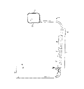
[012] Figure 1 is a side view of a personal viewing device.
[013] Figure 2 is a frontal view of a personal viewing device.
[014] Figure 3 is a rear view of a personal viewing device.
[015] Figure 4 is a perspective view of a personal viewing device.
[016] Figure 5 is a perspective view of a personal viewing device in use.
[017] Figure 6 is a perspective view of a personal viewing device with a
rotated branch member,
[018] Figure 7 is a perspective view of a base member.
[019] Figure 8 is a side view of a plurality of rods making up a mast member,
[020] Figure 9 is a perspective view of a branch member.
[021] Figure 10 is a side view of a branch member.
[022] Figure 11 is an end view of a branch member.
LEGAL_27031426 1 4
1008273-243877 (KB/SA)
CA 2933575 2017-05-24
[0231 Figure 12 is a side view of a branch member for application with a bed
mattress or other
flat surface.
[024] Figure 13 is a side view of a branch member with wheels.
[025] Figure 14 is a side view of a caddy.
DETAILED DESCRIPTION
[026] The present invention will now be described to provide an overall
understanding of the
principles of the structure, function, manufacture, and use of the devices and
methods disclosed
herein. One or more examples of the present invention are illustrated in the
accompanying
drawings. Those of ordinary skill in the art will understand that the devices
and methods
specifically described herein and illustrated in the accompanying drawings are
non-limiting
embodiments and that the scope of these embodiments is defined solely by the
claims. The
features illustrated or described in connection with one embodiment may be
combined with the
features of other embodiments. Such modifications and variations are intended
to be included
within the scope of the appended claims,
[027] In general, the present invention is directed to a portable,
freestanding, adjustable, and
deconstructable personal viewing device as can be seen in Figures 1 -14.
[028] As seen in Figures 1-4, the personal viewing device can comprise a base
member 2, a mast
member 4, and a branch member 6, The base member 2 can be removably coupled to
the mast
member 4, and the mast member 4 can be removably coupled to the branch member
6. The mast
member 4 can be excluded from the personal viewing device such that the base
member 2 and
the branch member 6 can be removably coupled. The base member 2 can be
configured as a
substantially U-shaped or V-shaped rod. The base member 2 can be a variety of
shapes and can
have one or more bends. The base member 2 can by substantially U-shaped or V-
shaped, but the
LEGAL_27031426 5
1008273-243877 (KB/SA)
CA 2933575 2017-05-24
=
ends of the base member 2 can extend outward such that the width of the base
member 2 is
greater than a base member 2 with ends that do not extend outward. The rod can
be cylindrical in
geometry and can have a range of diameters and can be varying lengths. The rod
can also be
configured to telescope such that the legs of the base member 2 can be
compressed and therefore
shortened, or the legs of the base member 2 can be extended and therefore
elongated. The bend
in the rod can be configured to include a stud 8 extending substantially
perpendicularly from the
rod (as shown in Figure 7). The rod that makes up the base member 2 can have
beveled ends 10
opposite the bend in the rod. The base member 2, mast member 4, and branch
member 6 can be
made from one or multiple pieces of material, such as metal.
029] Still referring to Figures 1 -4, the mast member 4 of the personal
viewing device can be
made up of a plurality of rods 12 of varying lengths (also shown in Figure 8).
The rods 12 can
have a sleeved end 14 and an unsleeved end 16. The rods 12 can be configured
such that the
unsleeved end 16 of one rod 12 can be inserted in to the sleeved end 14 of
another rod 12. The
rods 12 can be configured such that the unsleeved end 16 of one rod 12 can fit
completely or
partially into the sleeved end 16 of another rod 12. When engaged, the rods 12
that make up the
mast, member 4 can remain engaged without the use of fasteners, such as
rivets, screws, glue, or
clamps. The rods 12 can be disengaged from each other by sliding the sleeved
end 14 of one rod
12 off of the unsleeved end 16 of another rod 12. The mast member 4 can be
removably coupled
to the base member 2 by inserting the stud 8 from the base member 2 into the
sleeved end 14 of
one rod 12 of the mast member 4, The stud 8 and the rods 12 can be a variety
of diameters and
lengths, The embodiment of the present invention shown in Figures 1 -4 shows
one mast member
4 with one branch member 6 removably coupled thereto. However, it is to be
understood that in
various other embodiments of the present invention multiple mast members 4
could be
LEGAL_27031426 1 6
1008273-243877 (KB/SA)
CA 2933575 2017-05-24
removably coupled to the base member 2, with, each mast member 4 having a
branch member 6.
The rods 12 of the mast member 4 can be interchangeably coupled to each other
such that the
sleeved end 16 of one rod 12 can fit the unsleeved end 14 of any of the other
rods 12. and the
unsleeved end 14 of one rod 12 can fit into the sleeved end 16 of any of the
other rods 12.
[030] The mast member 4 can telescope such that the rods 12 that make up the
mast member 4
can be coupled and can extend and retract to create varying lengths of the
mast member 4. The
rods 12 of the mast member 4 can be configured to include a camlock or other
fastening means
such that when the rods 12 are coupled together, the camlock or other
fastening means can be
used to secure one rod 12 to another rod 12,
[031] Still referring to Figures 1 -4, the branch member 6 of the personal
viewing device can be
comprised of a proximal, sleeved end 18 and a distal end 20, The branch member
6 can be
removably coupled to the mast member 4 by inserting the unsleeved end 16 of
one rod 12 of the
mast member 4 into the proximal, sleeved end 18 of the branch member 6. The
branch member 6
can be bent or curved such that the portion of the branch member 6 making up
the distal end 20
can be substantially perpendicular to the proximal, sleeved end 18 of the
branch member 6. The
embodiment of the present invention as shown in Figures 1-4 shows a
substantially 90 degree
curve in the branch member 6. However, other embodiments of the present
invention, not shown
herein, can have a range of curves or can have no curve at all. The distal end
20 of the branch
member 6 can be configured to include an appliance 22, such as a mirror. At
least a portion of
the branch member 6 can be configured to telescope such that the branch member
6 can be
elongated or shortened.
[032] The components described above in the present disclosure and as shown in
Figures 1-4 can
be removably coupled, without the use of screws, rivets, nuts and bolts, or
other fastening or
LEGAL_27031426 1 7
1008273-243877 (KB/SA)
CA 2933575 2017-05-24
locking means. The sleeved and unsleeved ends of the various components
described above can
be honed, tapered, or conical in design as opposed to cylindrical. Each of the
components
described above can be removed from the other components without damage to the
personal
viewing device and with minimal dexterity or efforts by the user.
[033] As seen in Figures 1-4, when the base member 2, the mast member 4, and
the branch
member 6 are removably coupled together to form the personal viewing device,
the device can
be freestanding with the base member 2 making contact with a floor or other
similar surface.
[034] As seen in Figure 5, when the base member 2, the mast member 4, and the
branch member
6 arc removably coupled together to form the personal viewing device, the base
member 2 can be
inserted beneath a bed, mattress, or other flat surface, allowing the mast
member 4 to extend
upwards next to the bed, mattress, or other fiat surface, and allowing the
branch member 6 to
extend above and over the bed, mattress, or other flat surface. The beveled
ends 10 can aid in
inserting the base member 2 of the personal viewing device between two
objects, such as
between a mattress and a box spring. The branch member 6 can rotate about the
point where the
branch member 6 is coupled to the mast member 4, such that a patient, when in
a supine position,
can rotate the branch member 6 over his or her body or can rotate the branch
member 6 away
from his or her body. The ability to rotate the branch member 6 can allow the
patient to use the
appliance 22 on the branch member 6 when desired, and then move the branch
member 6 away
from him or herself when not in use.
[035] As seen in Figure 6, the branch member 6 can rotate about the point
where the proximal
sleeved end 18 of the branch member 6 meets with the mast member 4. As shown
in Figures 1 -
4, the branch member 6 can be positioned such that the branch member 6 is
substantially over
top of and parallel to the base member 2. As shown in Figure 6, the branch
member 6 can be
LEGAL_27031426 1 8
1008273-243877 (KB/SA)
CA 2933575 2017-05-24
positioned to be rotated 180 degrees from the position shown in Figures 1 -4
such that the branch
member 6 extends from the roast member 4 in the opposite direction of the base
member 4. The
branch member 6 can also be rotated at any angle about the point where the
branch member 6
meets with the mast member 4. As shown in Figure 6, even with the branch
member 6 positioned
180 degrees in the opposite direction of the base member 4, the personal
viewing device can be
freestanding. The rotatable branch member 6 can allow for a user to view
him/herself from a
number of standing, sitting, or supine positions.
[036] As seen in Figure 9, the distal end 20 of the branch member 6 can have
one or more slits
24 capable of receiving an appliance 22. As shown in Figure 9, the distal end
20 of the branch
member 6 has two slits 24 positioned substantially on the top side of the
branch member 6. The
width and length of the slits 24 can vary depending on the desired application
and the desired
appliance 22 to be removably coupled to the branch member 6. While the
invention shown in
Figure 9 shows the slits 24 as narrow grooves, it is to be understood that any
geometric
configuration of the slits 24 can be used in the branch member 6.
Additionally, while the slits 24 as shown in Figure 9 are depicted on the
distal end 20 of the
branch member 6, the slits 24 can also be placed at any position between the
distal end 20 and
the curve in the branch member 6. Furthermore, multiple slits 24 can be
included on a branch
member 6 to removably couple to multiple appliances 22, or to allow an
appliance 22 to be
placed in one of multiple locations on the branch member 6. This can allow the
personal viewing
device to be used for multiple purposes and allow for various device sizes.
LEGAL_27031426 1 9
1008273-243877 (KB/SA)
CA 02933575 2016-06-10
WO 2015/095476 PCT/US2014/071076
The appliance 22 can also be affixed to the branch member 6, such as by
soldering, screws,
and other fastening means. The slits 24 can also be placed on the sides,
bottom, and end of
the branch member 6. The slits 24 can also extend through the top and bottom
of the branch
member 6 such that when the appliance 22 is received by the slits 24, at least
a portion of the
appliance 22 can be inserted through the slits 24 from the top of the branch
member 6,
extending through the branch member and out the bottom of the slits 24 on the
bottom of the
branch member 6. The distal end 20 of the branch member 6 may also include a
post or stud
configured to receive at [cast a portion of the appliance 22.
[0371 As shown in Figures 10-11, the appliance 22 can be removably coupled to
the branch
member 6 on the branch member's distal end 20. As shown in Figures 10-11, the
appliance
22 is a mirror. Other appliances 22, not shown herein, can be used in the
place of or in
addition to a mirror, such as a flashlight. The appliance 22 can be affixed to
the branch
member 6 by soldering, screws, or other fasteners.
[0381 As shown in Figure 12, the base member 2 can include a rod configured in
geometries
other than cylindrical. The rod of the base member 2 can be substantially
flat. A flat base
member 2 can allow a patient to more easily slide the base member 2 between
two fiat
surfaces, such as between a mattress and a bed frame or a mattress and a
floor. Like the base
member 2 discussed above with a cylindrically shaped rod, the base member
depicted in
Figure 12 can be removed from the mast member 4 with limited dexterity. The
present
invention can include at least two base members 2, one with a cylindrically
shaped rod and
one with a flat rod, and the two base members 2 can be used interchangeably.
[039] Referring next to Figure 13, the base member 2 can be configured to
include one or
more wheels 26 on the bottom of the base member 2. The wheels 26 can allow the
personal
viewing device to be rolled from one area to another, such as from a bedroom
to a bathroom.
CA 02933575 2016-06-10
WO 2015/095476 PCT/1JS2014/071076
The wheels 26 can he affixed to the base member 2, such as by soldering,
screws, or other
fastening means, The wheels 26 can also be removably coupled to the base
member 26 such
that a patient who did not desire the USC of the wheels 26 could remove them
to achieve a
configuration shown in Figures 1-4.
[040] As described above, the various elements of the personal viewing device
described
herein can be removably coupled to each other, such that each of the elements
can be
removed as individual elements. When the personal viewing device is
disassembled, its
components can be stored in a bag, a case, or on a caddy, for example. As
shown in Figure
14, a caddy configured to receive the components of the personal viewing
device is shown.
The caddy can have receptacles capable of receiving and storing the base
member 2, the mast
member 4, and the branch member 6. The caddy can he configured to include
wheels such
that the caddy can be transported with or without the components of the
personal viewing
device stored on it.
[0411 Also as described above, the personal viewing device described herein
can be of
varying sizes and scales. For example, the personal viewing device may be
approximately
four to five feet tall when its various elements are removably coupled. The
personal viewing
device can also be scaled down such that the device is one foot tall when its
various elements
are removably coupled.
[042] The present disclosure can be made of one or more of various materials,
including but
not limited to metal and plastic. When made of metal, the present disclosure
can be made of
any metal with suitable strength and malleability, such as steel, to create
the device described
herein The rods making up the base member 2, mast member 4, and branch member
6 can
be hollow to allow for a lighter personal viewing device. The bends in the
base member 2
and branch member 6, as described above and as shown in the Figures hereto can
be formed
, 11
CA 02933575 2016-06-10
WO 2015/095476 PCT/1JS2014/071076
using techniques known to those having skill in the art of metal working. The
stud 8 can be
affixed to the base member 2 such as by soldering. The slits 24 in the branch
member 6 can
be made by grinding or tooling grooves into the branch member 6 in the
locations described
above. When made using plastics, polymeric material can be injection molded to
create the
components of the personal viewing device.
[043] In use, the various components of the personal viewing device can be
assembled in
any order. By way of example, the unsleeved end 16 of one rod 12 snaking up
the mast
member 4 can be received by the sleeved end 14 of another rod 12, such that
two rods 12
make up the mast member 4. The unsleeved end 16 of the top rod 12 can make up
the top of
the mast member 4 and the sleeved end 14 of the bottom rod 12 can make up the
bottom of
the mast member 4. The mast member 4 can then be removably coupled to the base
member
2 by sliding the sleeved end 14 of the bottom rod 12 from the mast metnber 4
over the stud 8
on the base member 2. The branch member 6 can then be removably coupled to the
roast
member 4 by sliding the unsleeved end 16 of the top rod 12 from the mast
member 4 into the
sleeved end 18 of the branch member 6. The appliance 22 can then be removably
coupled to
the branch member by inserting a portion of the appliance 22 into the slits 24
on the distal
end 20 of the branch member 6.
[044] When assembled, the personal viewing device can be. freestanding. When
the
appliance 22 is a mirror, the mirror can swivel or pivot such that a patient
can view his or
herself from a number of angles. The patient may then positron him or herself
in the seated
or standing position to view the desired area of the body, rotating the branch
member 6 and
pivoting the mirror as desired. The patient may also place the base member 2
beneath a bed
or other surface such that the branch member 6 extends above the bed, The
patient may then
12
CA 02933575 2016-06-10
WO 2015/095476 PCT/LS2014/071076
lie in the supine position on the bed or other surface, rotate the branch
member 6 over the
desired area of his or her body, and pivot the mirror to view him or herself.
[045] When the patient has finished using the personal viewing device, the
patient may
leave the device assembled or may choose to disassemble the device, The
personal viewing
device can be disassembled in the same order as described above or in a
different order by
sliding the sleeved ends of the various components off of the unsleeved ends
of neighboring
components.
[046] While this invention has been described as having exemplary designs, the
present
invention may be further modified within the spirit and scope of the
disclosure. This
application is therefore intended to cover any variations, uses, or
adaptations of the invention
using its general principles. Ruther, this application is intended to cover
such departures
from the present disclosure as come within known or customary practice in the
art to which
this invention pertains.
[047] In one general aspect, the present disclosure is directed to a personal
viewing device
that can comprise a base member for resting on a resting surface, wherein the
base member
can be coupled to a mast member that extends from the base member in a
direction that is not
parallel to the resting surface, The mast member can be coupled to a branch
member that
extends from the mast member, wherein the branch member can comprise a first
portion that
extends in a direction that is not parallel to the direction that the mast
member extends from
the base member arid parallel to the resting surface. The base member can
comprise a bent
rod that rests on the resting surface with a stud extending from the bent rod,
and with the
mast member coupled to the stud of the base member. The mast member can
comprise two
or more rods each having a sleeved end and an unsleeved end, and the two or
more rods can
be coupled to each other by inserting the unsleeved end of one rod into the
sleeved end of
13
CA 02933575 2016-06-10
WO 2015/095476 PCT/US2014/071076
another rod. 'rhe branch member can comprise a sleeved end that couples to the
unsiceved
end of the rods that make up the mast member. The branch member can hold at
least one
appliance, and the base member, mast member, branch member, and appliance can
be
assembled without the use of a tool.
[048] in various implementations, the base member, mast member, branch member,
and
appliance can be removably coupled without screws, rivets, nuts and bolts, or
other fasteners.
Also, the base member can be substantially U-shaped with the stud situated in
the bend of the
base member. The branch member may also comprise a proximal end that removably
couples to the mast member, and a distal end that can removably couple to the
appliance,
wherein the distal end of the branch member can include at least one slit and
the appliance
can be at least partially received by the slit of the branch member,
Furthermore, the
appliance can be a mirror or a light. Also, the mast member can be
substantially
perpendicular to the base member when the mast member and the base member arc
removably coupled, and the branch member can have a sleeved end that removably
couples
to the mast member wherein the branch member can comprise a bend near the
sleeved end
such that at least a portion of the branch member is substantially parallel to
the base member.
The bent rod of the base member can comprise beveled ends, and the base
member, mast
member, and branch member, when removably coupled, can be freestanding. The
base
member can fit under a flat surface or between two surfaces, The branch
member, when
removably coupled to the mast member can rotate with the point of rotation at
the junction
between the branch member and mast member. The base member, mast member, and
branch
member can comprise steel rods, with the rods having an at least partially
hollow interior.
Also, the bent rod of the base member can be substantially flat. The base
member can also
14
CA 02933575 2016-06-10
WO 2015/095476 PCT/1S2014/071076
comprise at least one wheel extending from the base member opposition the
direction of the
stud.
[049] In another general aspect, the present disclosure is directed a persona]
viewing device
comprising a base member for resting on a resting surface, wherein the base
member can be
coupled to a branch member that extends from the mast member and the branch
member can
comprise a first portion that extends in a direction that is parallel to the
base member, The
branch member can be further configured to hold at least one mirror, and when
coupled, the
base member and branch member can be freestanding.
10501 in various implementations, the mirror can swivel about the point where
the minor
meets the branch member, Also, the base member can comprise a bent rod with a
stud
extending from the bent rod with the mast member coupled to the stud of the
base member,
and wherein the branch member can include a sleeved end that couples to the
stud of the base
member,
[051] In another general aspect, the present disclosure is directed to a
personal viewing
device comprising a base member for resting on a resting surface, wherein the
base member
can be removably coupled to a mast member that extends from the base member
and is not
parallel to the resting surface. The mast member can be removably coupled to a
branch
member that extends from the mast member, wherein the branch member can
comprise a first
portion that extends in a direction that is not parallel to the direction that
the mast member
extends from the base member. Also, the branch member can hold at least one
appliance, and
the base member, mast member, and branch member can disassemble from each
other
without the use of a tool. When disassembled, the base member, mast member,
and branch
member can fit into a moveable container.
[052] In various implementations, the moveable container can be no larger than
a backpack.