Note: Descriptions are shown in the official language in which they were submitted.
CA 02934234 2016-06-28
CASING SHELL ELEMENT
Field
[0001] The instant disclosure relates to a casing shell element with the
features as described herebelow. The casing shell element is used for
fabricating casings for casting concrete for construction, in particular for
casing
concrete walls. The casing shell element includes a frame at which a casing
shell is attached. The casing shell is typically a plate made from wood or
plastic material. The frame is used for stiffening the casing shell, for
arranging
supports at the casing shell element and/or for connecting with additional
casing shell elements.
Background
[0002] Casing shell elements of this general type are known. For so
called double head casings where two casing shell elements are arranged at a
distance from each other so that concrete can be cast between the opposite
casing shell elements for example for building a concrete wall the casing
shell
elements that are arranged opposite to each other are connected with each
other by rods which are designated as anchors. The anchors reach through the
anchor holes in the casing shell of the casing shell elements and are for
example attached with nuts at a back side of the frame. The back side is a
side
of the casing shell element that is oriented away from the casing shell.
Summary
[0003] Thus, the present disclosure aims to provide a casing shell
element
which helps facilitate different attachments of anchors or the attachment of
different anchors.
[0004] According to an embodiment of the disclosure, a casing shell
element for casing concrete comprises a casing shell which is arranged at a
frame and which includes an anchor hole for inserting an anchor; and an
attachment device providing a disengageable and tension proof connection of
1
CA 02934234 2016-06-28
an anchor with the casing shell element, wherein the attachment device is
movably attached at the casing shell element and includes at least one
attachment facility for the anchor, wherein the at least one attachment
facility is
movable into an operating position by moving the attachment device, and
wherein the anchor is connectable through the anchor hole in a disengageable
manner with the attachment device in the operating position of the attachment
facility. More specifically, the casing shell element according to the
disclosure
includes an attachment device which is movably arranged at the casing shell
element and at least one attachment facility for an anchor. Attachment
facilities
of this type can be interior threads for threading in an anchor, pass through
holes or other devices or options for a friction locking and/or form locking
attachment of an anchor at the casing shell element. In particular the at
least
one attachment facility includes an internal thread for threading in an anchor
that includes a thread, for example a Dywidag-rod. The attachment device is
used for a disengageable tension proof connection of an anchor with the casing
shell element. Through the movability at the casing shell element the
attachment device can be moved into an operating position in which an anchor
is connectable in a disengageable manner with the at least one attachment
facility through an anchor hole in the casing shell. In embodiments of the
disclosure it is possible to move the attachment device sideways which
attachment device is movably attached at the casing shell element, so that an
anchor is insertable through the anchor hole and attachable bypassing the
attachment device for example by an anchor nut at a back side of the casing
shell element. Moving sideways means that the attachment device is movable
into an orientational position in which it does not cover the anchor hole in
the
casing shell so that an anchor is insertable through the anchor hole in the
casing shell past the attachment device. Sideways can also mean in upward
direction or in downward direction.
[0005] An embodiment of the disclosure provides that the attachment
device has plural attachment facilities for different anchors. The movability
at
the casing shell element facilitates moving the attachment device into an
operating position in which an anchor is optionally connectable with one of
the
attachment facilities through an anchor hole in the casing shell. The
attachment device includes an operating position for each attachment facility
2
CA 02934234 2016-06-28
and is moved into the operating position of the selected attachment facility
by
moving the attachment device at the casing shell element. This embodiment of
the disclosure does not preclude that the attachment device is also movable
sideways so that an anchor is insertable through the anchor hole in the casing
shell bypassing the attachment device.
[0006] Tension proof with respect to the anchor means that the anchor
is
connected or connectable with the casing shell element so that it is loadable
with tension. This does not preclude a connection that is fixated in another
direction, for example a connection that is compression proof or shear proof
or
pivot proof. In order to compensate angular misalignments the connection can
be pivotable or allowing pivoting the anchor.
[0007] Moveably, for example rotateably or pivotable does not only
mean a
move ability of the attachment device overall relative to the casing shell
element
but also includes a move ability of the portion of the attachment device, for
example of an anchor counter piece.
[0008] In an embodiment of the disclosure, different anchors may be
attached at the casing shell element. The disclosure also may help facilitate
embodiments for optional unilateral or two sided anchoring. In a two sided
anchor nuts are threaded onto the anchor at back sides that are oriented away
from each other of casing shell elements of a double head casing that are
oriented opposite to each other at a distance, thus the anchor can be loaded
at
both casing shell elements by rotating the anchor nuts. For one sided
anchoring the anchor is fixated at one casing shell element at least in a
tension
direction and has to be loaded at another opposite casing shell element. This
requires different attachment facilities for the anchor at the opposite casing
shell elements for example a pass through hole at one casing shell element and
an internal thread at the other casing shell element. This is facilitated by
the
disclosure, wherein the choice of the attachment facilities is still possible
any
time by moving the attachment device even after the casing shell has been set
up. In an embodiment of the disclosure the attachment device can be arranged
at the casing shell element and that it is not a separate component.
[0009] One embodiment of the disclosure provides a position securing
device which supports the attachment device in at least one operating
position.
The position securing device can function self-acting or can be actuatable
3
CA 02934234 2016-06-28
manually or in another manner. The position securing device prevents
unintentional or gravity induced movement of the attachment device from a
selected operating position and facilitates intentional movement of the
attachment device from one operating position into another operating position.
One option of a position securing device is a snap locking device which snap
locks in the at least one operating position of the attachment device and
which
can be unlocked by a force in movement direction to move the attachment
device into another operating position. A snap locking device functions self-
acting. Another option of a position securing device is a manually operable
1.0 dead bolt or a similar locking element which supports the attachment
device in
the operating positions. The enumeration is exemplary and not exclusive.
[0010] In an embodiment of the disclosure, the attachment device is
pivotably attached at the casing shell element. One embodiment provides that
the attachment device includes intersecting attachment facilities which
intersect
a pivot axis about which the attachment device is pivotable. Pivoting the
attachment device about its pivot axis facilitates moving a desired attachment
facility of the attachment device into the operating position.
[0011] Another embodiment of the disclosure provides that the
attachment
device is movably attached at the casing shell element. An attachment device
can include plural attachment facilities. An embodiment with plural movable
attachment devices respectively including one or plural attachment facilities
is
also conceivable. Moving the attachment devices facilitates moving one
attachment facility into the operating position.
[0012] In particular the attachment device includes an attachment
facility
with an interior thread for threading in an anchor with a thread and an
attachment facility without a thread for passing an anchor through. Other
attachment facilities are not excluded.
[0013] In an embodiment of the disclosure, the attachment device does
not
protrude beyond the frame at a back side of the casing shell element. This
facilitates storing and transporting casing shell elements in contact with
each
other and thus in a space saving manner. Furthermore, in an embodiment of
the disclosure, the attachment device does not protrude beyond the casing
shell element at sides so that two casing shell elements can be arranged in
contact with each other adjacent to each other or on top of each other.
4
CA 02934234 2016-06-28
[0014] An embodiment of the disclosure provides that the attachment
device is arranged at one side of a strut of the frame of the casing shell
element. This facilitates a stable attachment of the attachment device at the
casing shell element. One embodiment provides an attachment of the
attachment device in an intermediary space between two struts of a double
strut of the frame of the casing shell element. Two parallel struts are
designated as a double strut wherein a distance of the strut from each other
is
not more than a width or twice or three times a width of the struts. This
embodiment of the disclosure facilitates a stable and space saving attachment
of the attachment device at the casing shell element.
[0015] An alternative embodiment of the disclosure facilitates
arranging the
attachment device in a strut of the frame of the casing shell element. Since
the
struts of the frames of casing shell elements typically are rectangular tubes
this
is possible. Also in other profiles, for example in U-profiles configured as
struts
it is feasible without any problem to house the attachment device. Arranging
the attachment device in one strut of the frame is mechanically stable, does
not
use any space outside of the strut and protects the attachment device against
contamination.
Brief description of drawings
[0016] The disclosure is subsequently described based on embodiments
with reference to drawing figures, wherein:
[0017] FIG. 1 illustrates a partial sectional view of a casing shell
element
according to the disclosure in a perspective view;
[0018] FIG. 2 illustrates a cross section of an attachment device of
the
casing shell element of FIG. 1 in an operating position;
[0019] FIG. 3 illustrates the attachment device of FIG. 2 in another
operating position;
[0020] FIG. 4 illustrates a partial sectional view of a casing shell
element
with a modified attachment device according to the disclosure in a perspective
view corresponding to FIG. 1;
5
CA 02934234 2016-06-28
[0021] FIG. 5 illustrates a cross section of the attachment device in
FIG. 4
in an operating position;
[0022] FIG. 6 illustrates the attachment device of FIG. 5 in another
operating position; and
[0023] FIG. 7 illustrates a third embodiment of a casing shell element with
an attachment device according to the disclosure in an illustration
corresponding to FIG. 1.
Detailed description
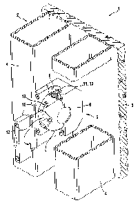
[0024] FIG. 1 illustrates a partial sectional view of a casing shell
element 1
according to the disclosure which is used for casing concrete. The casing
shell
element 1 includes a frame 2 on which a plate is arranged that is made for
example from wood or plastic material that forms the casing shell 3. The frame
2 is a flat frame 2 made from rectangular metal tubes that are arranged in
parallel and at right angles relative to each other forming struts 4. The
frame 2
partially includes double struts 4 which means two struts 4 which are arranged
in parallel with each other and which are arranged at a distance from each
other which approximately corresponds to their width. Between two struts 4 of
such double struts attachment devices 5 according to the disclosure are
arranged wherein one of the attachment devices is drawn in FIGs. 1 ¨ 3. The
attachment devices 5 are arranged in a pattern distributed over the surface of
the casing shell element 1 or of the casing shell 3. FIG. 1 illustrates a
partial
sectional view of one of the two struts 4 in the portion of the attachment
device
5 so that it does not cover the attachment device 5. In embodiments of the
disclosure the attachment device 5 can also be arranged in one strut 4 (not
illustrated).
[0025] The attachment device 5 includes a reaction bearing 6 in which
an
anchor counter piece 7 is rotatably received. The reaction bearing 6 is block
shaped and has the same width as the distance between the two struts 4 of the
double strut. The reaction bearing 6 contacts the casing shell 3 and is
attached
at both struts 4, for example welded together with them or threaded together.
The reaction bearing 6 includes a U-shaped groove 8 that is parallel to both
6
CA 02934234 2016-06-28
struts 4 and parallel to the casing shell 3 in which groove the anchor counter
piece 7 is inserted.
[0026] The anchor piece 7 is circular with a rounded circumferential
surface in a side view transversal to the struts 4 of the frame 2 and parallel
to
the casing shell 3. The anchor counter piece is inserted so that it is
rotatable
about its axis in a congruent semi-circular receiver 9 with an identically
cambered circumferential surface of the reaction bearing 6. The anchor
counter piece 7 is supported by two bar shaped supports 10 which are
arranged at sides of the reaction bearing 6 laterally from the groove 8 on a
back
side at the reaction bearing wherein the back side is oriented away from the
casing shell 3. The supports 10 include semi-circular indentations that are
congruent to the anchor counter piece 7 at insides of the supports that are
oriented towards each other. The supports 10 can be for example bolted
together with the reaction bearing 6. Another option are supports 10 made from
plastic material which are interlocked with the reaction bearing 6 so that
they
can and have to be destroyed and replaced for an exchange of the anchor
counter piece 7.
[0027] The anchor counter piece 7 includes pass through holes 11, 12
intersecting at a right angle at a rotation axis of the anchor opposite piece.
The
pass through holes 11, 12 are arranged at a plane that is perpendicular to the
casing shell 3 and parallel to both struts 4. One of the two pass through
holes
11 includes an inner thread for threading in a non-illustrated rod shaped
anchor.
The inner thread 13 is provided in particular for threading in a so called
Dywidag-rod as an anchor. The other pass through hole 12 is provided without
a thread, however, a non-illustrated rod shaped anchor can be inserted through
it and can be connected tension proof with the casing shell element by
threading on a non-illustrated anchor nut on a back side of the attachment
device 5 oriented away from the casing shell 3 or of the struts 4 of the frame
2.
The pass through holes 11, 12 can be generally considered as different
attachment facilities for identical or different anchors.
[0028] In a radial direction to the rotation axis of the anchor
counter piece
7 and perpendicular to the casing shell 3, the casing shell 3 and the reaction
bearing 6 include pass through holes which can also be considered as anchor
holes 14, 15 for a pass through of a rod shaped anchor. Rotating the anchor
7
CA 02934234 2016-06-28
counter piece 7 facilitates optionally aligning one of the pass through holes
11,
12 which form the different attachment facilities with the anchor holes 14, 15
in
the casing shell 3 and with the reaction bearing 6. A non-illustrated anchor
can
be inserted from the outside of the casing shell through the anchor holes 14,
15
into the aligned pass through hole 11, 12 of the anchor counter piece 7 as
well
as from the back side through the pass through hole 11, 12 and the anchor
holes 14, 15.
[0029] For rotating the anchor counter piece 7 includes two pass
through
holes 19 intersecting at a right angle in the rotation axis of the anchor
counter
piece, wherein the pass through holes are arranged at angles of 45 relative
to
the pass through holes 11, 12 forming the different attachment facilities for
anchors and in a plane with these pass through holes 11, 12 in the anchor
counter piece 7. The anchor counter piece 7 can be rotated for example with a
pin, screw driver or small hammer which is inserted into one of the pass
through holes 19 and optionally one of the pass through holes 11, 12 which
form the different attachment facilities for an anchor can be aligned with the
anchor holes 14, 15 in the casing shell 3 and with the reaction bearing 6.
[0030] Spring loaded ball bushings 16 are respectively threaded into
one
end of the pass through holes 14 used for turning the anchor counter piece 7
wherein the spring loaded ball bushings include balls 17 which are pressed
outward under a spring load. When one of the two pass through holes 11, 12
which include the different attachment facilities for anchors is aligned with
the
anchor holes 14, 15 the balls 17 snap into bevels 18 in a circumference of the
semi-circular receiver 9 for the anchor counter piece 7 in the reaction
bearing 6.
The spring loaded ball bushings 16 co-operating with the recesses 18 form
snap locking devices which support the anchor counter piece 7 in the rotating
positions in which the pass through holes 11, 12 which form the different
attachment facilities for anchors are aligned with the anchor holes 14, 15 in
the
casing shell 3 and in the reaction bearing 6. These rotating positions of the
anchor counter piece 7 can also be considered as operating positions of the
anchor counter piece 7. In general the snap locking devices can also be
considered as position securing devices which support the anchor opposite
piece in the rotating positions or in the operating positions. Other positon
securing devices for the operating positions of the anchor counter piece 7 are
8
CA 02934234 2016-06-28
feasible, for example a manually operable locking bar or a similar locking
element (not illustrated).
[0031] In FIG. 4 the anchor counter piece 7 has the shape of a
symmetrical ball zone and contacts a congruent receiver of the reaction
bearing
6. Thus, the anchor counter piece 7 is not only pivotable about its axis but
pivotable like a ball joint in all directions. By rotating about its axis the
anchor
piece of FIG. 4 is pivotable into operating positions as evident from FIGs. 1
¨ 3
in which optionally a pass through hole 11, 12 of the pass through holes 11,
12
intersecting each other and the axis of the anchor counter piece is aligned
with
an anchor hole 14 in a casing shell of a casing shell element 1 in order to be
able to fixate a non-illustrated anchor in a disengage able manner. By
providing pivotability transversal to the axis the anchor counter piece 7 of
FIG. 4
compensates angular alignment deviations.
[0032] As illustrated in FIGs. 5 and 6 one of the pass through holes
11
includes an inner thread 13 for threading in a so called Dywidag-rod forming
an
anchor and the other pass through hole 12 is configured without a thread for
passing an anchor through which is fixated for example by an anchor nut on a
back side of the attachment device 5 oriented away from the casing shell 3 or
by struts 4 of the casing shell element 1.
[0033] FIGs. 4 ¨ 6 lack the pass through holes that are arranged at an
angle of 450, the anchor counter piece 7 is for example rotated by a rod,
screw
driver, anchor or small hammer that is inserted into the pass through holes
11,
12. A cover 22 which is attached at the reaction bearing 6 instead of the
supports 10 and which supports the anchor counter piece 7 rotatably in all
directions in the receiver 9 of the reaction bearing 6 and the reaction
bearing 6
include an opening 23 which extends over slightly more than 90 so that the
pass through holes 10, 11 are accessible in both operating positions and so
that the anchor counter piece 7 is rotatable. The cover 22 is closed on top in
order to protect the anchor counter piece 7 against contamination. "On top"
refers to a position of the attachment device 5 when the casing shell element
is
set up for pouring concrete as intended. The cover 22 is fixated with a bolt
24
at the reaction bearing and interlocked at two other locations. The cover 22
is
removable after the screw 24 is disengaged.
9
CA 02934234 2016-06-28
[0034] The reaction bearing 6 includes a rib 25 in the receiver 9 for
the
anchor counter piece 7, wherein the rib extends in a rotation direction of the
anchor counter piece 7, wherein the rib engages a groove 26 which extends in
the anchor counter piece 7 also in the rotation direction of the anchor
counter
piece 7. The rib 25 engaging the groove 26 supports the anchor counter piece
7 so that it is rotatable about its axis. At one end the groove 26 is as wide
as
the rib 25 so that the anchor counter piece 7 is not pivotable transversal to
the
axis when the rib 25 is arranged in this portion of the groove 26. At the
other
end the groove 26 is wider than the rib 25 so that the anchor counter piece 7
is
pivotable sideways for compensating angular alignment deviations of an anchor
with a pivot angle of for example 5 towards both sides. The rib 25 is
arranged
in a wide portion of the groove 26 when the pass through hole 11 of the anchor
counter piece 7 including the interior thread 13 is aligned with the anchor
hole
14 in the casing shell 3 so that an angular alignment deviation of an anchor
that
is threaded into the pass through hole 11 is compensated. When the
unthreaded pass through hole 12 of the anchor counter piece 7 is aligned with
the anchor hole 14 in the casing shell 3 the rib 25 does not have any
clearance
in the groove 26.
[0035] FIGs. 4 ¨ 6 illustrate a spring loaded ball bushing 16 that is
arranged in the cover 22 instead of being arranged in the anchor counter piece
7. The spring loaded ball bushing could also be arranged in the reaction
bearing. Is ball 17 interacts with two ball shaped bevels 18 in the
circumference of the anchor counter piece 7 and supports the anchor counter
piece 7 in the two operating positions. The bevels can also have another shape
they can be for example conical (not illustrated). For example conical bevels
facilitate a support without clearance of the anchor counter piece 7 in the
operating positions without compensating movements for balancing angular
misalignments. The bevel 18 in which the ball 17 is arranged when the pass
through hole 11 including the internal thread 13 of the anchor counter piece 7
is
aligned with the anchor hole 14 in the casing shell 3 is larger and deeper so
that a clearance in the direction of rotation of the anchor counter piece 7
and
transversal to the rotation direction is provided for compensating angular
alignment deviations. A spring loading of the sphere 17 of the spring loaded
ball
bushing 16 towards the base of the bevel 18 causes an aligned orientation of
CA 02934234 2016-06-28
the pass through hole 11 of the anchor counter piece 7 with the anchor hole 14
in the casing shell 3. A deflection of the anchor counter piece 7 is provided
against a spring force of the spring ball bushing 16. As illustrated in FIGs.
1-3
the spring ball bushing 16 and the bevel 18 form a snap locking device or
generally a position securing device which supports the anchor counter piece 7
in the operating positions.
[0036] Additionally the attachment device 5 of FIGs. 4 ¨ 6 is
configured
identical and functions in the same manner as the attachment device
illustrated
in FIGs. 1 -3 so that the descriptions of FIGs. 1 ¨ 3 can be referred to in
order
to describe FIGs. 4 ¨ 6 in order to avoid repetition. Identical components
have
identical reference numerals.
[0037] FIG. 7 illustrates a casing shell element 1 with a modified
attachment device 5. Identical reference numerals are used for components in
FIG. 7 that are identical with components in FIGs. 1 ¨ 3 in the subsequent
description. The attachment device 5 in FIG. 7 is also arranged between two
struts 4 of a double strut of a frame 2 of the casing shell element 1. An
anchor
counter piece 7 is cuboid and movable in a longitudinal direction of the
struts 4
instead of being rotatable. The attachment device 5 includes a sliding support
for the anchor counter piece 7 wherein the sliding support is shaped as a
20 rectangular tube that is open on one side and which is for example
bolted
together or welded together with the struts 4. The open side of the sliding
support 20 is arranged on a back side of the casing shell element 1, thus it
is
oriented away from the casing shell 3. An inner cross section of the sliding
support 20 corresponds with a cross section of an anchor counter piece 7, so
that the anchor counter piece 7 is slideably supported in the sliding support
20.
The sliding support 20 includes inward bent lobes 21 at respective ends
wherein the lobes limit a movement path of the anchor counter piece 7 and
support the anchor counter piece 7 in the sliding support 20.
[0038] The anchor counter piece 7 includes two pass through openings
11,
12 that are parallel to each other. As illustrated in FIGs. 1 ¨ 3 a pass
through
hole 11 includes an inner thread 13 for threading in a threaded non-
illustrated
anchor and the other pass through opening 12 is configured without a thread
for
passing an anchor through. The two pass through holes 11, 12 of the movable
11
CA 02934234 2016-06-28
anchor counter piece 7 of FIG. 7 form different attachment facilities for
anchors
like the pass through holes 11, 12 in FIGs. 1 -3.
[0039] In end positions of the anchor counter piece 7 in which the
anchor
counter piece 7 contacts inward bent lobes 21 of the sliding support 20 one
respective pass through hole 11, 12 which form the respective attachment
facilities for the anchor is aligned with an anchor hole that is not visible
in FIG. 7
which extends through the casing shell 3 and the sliding support 20 so that a
non-illustrated anchor is insertable through the casing shell 3 into the
respective
pass through hole 11, 12 of the anchor counter piece 7 or vice versa from the
back side of the casing shell element 1 through the respective pass through
hole 11, 12 of the anchor counter piece 7 through the anchor hole in the
sliding
support 20 and in the casing shell 3.
[0040] At one side surface the anchor counter piece 7 includes a
spring
loaded ball bushing 16 whose ball 17 is pressed outward by a spring against an
inside of a side wall of the sliding support 20. In the side wall of the
sliding
support 20, two bevels are arranged that are not visible in the drawing
wherein
the ball 17 snaps into the bevels in end positions of the anchor counter piece
7.
The end positons of the anchor counter piece 7 are operating positions in
which as described one of the respective pass through openings 11, 12 which
form the different attachment facilities for the anchor is aligned with the
anchor
hole in the sliding support 20 and in the casing shell 3 so that it is useable
for
connecting an anchor with the attachment device 5 of the casing shell element
1. Also here the spring loaded ball bushing 16 and the bevel form a snap
locking device or generally a position securing device which supports the
anchor counter piece 7 in the operating positions.
[0041] For compensating angular misalignments the anchor counter piece
7 can have one or plural convex and/or arcuate outer surfaces and clearance in
the sliding support 20 (not illustrated) so that the anchor counter piece 7 is
pivotable about its longitudinal axis and/or transversal axis.
[0042] As a matter of principle the anchor counter piece 7 can also include
only one pass through hole 11, preferably the pass through hole 11 including
the inner thread 13 (not illustrated) and can be movable in a sideways
direction
by the movability of the anchor hole 14 in the casing shell 3 so that either
the
pass through hole 11 with the inner thread 13 is useable for threading an
12
CA 02934234 2016-06-28
anchor in or the anchor hole 14 without the anchor counter piece 7 is useable
for inserting an anchor past the anchor counter piece 7. This option is also
provided when the anchor counter piece 7 includes plural pass through holes
10, 11. Also with a pivotable attachment of an anchor counter piece 7 at the
casing shell element 1 it is possible to move the anchor counter piece 7 from
the anchor hole 14 in the casing shell 3 sideways so that an anchor is insert
able past the anchor counter piece 7 through the anchor hole 14 (not
illustrated). Moving the anchor counter piece 7 sideways includes a movement
in upward or downward direction. Of particular importance is the option to be
able to insert an anchor past the anchor counter piece 7 through the anchor
hole 14 in the casing shell 3.
13