Note: Descriptions are shown in the official language in which they were submitted.
CA 02934380 2016-06-28
PRESSURE COMPENSATED LOAD SENSE HYDRAULIC SYSTEM EFFICIENCY
IMPROVEMENT SYSTEM AND METHOD
Field of the Disclosure
[0001] The present disclosure relates to hydraulic systems, and more
particularly to a
system and method that improves the efficiency of pressure compensated load
sense hydraulic
systems.
Background
[0002] Pressure compensated load sense hydraulic systems are used in many
industries,
including for example mobile construction and forestry equipment. Pressure
compensated
load sense systems allow for better multi-functioning performance due to
improved flow
sharing with pressure compensation. Without pressure compensation, the flow in
a hydraulic
system will go to the flow path of least resistance. For example, when
commanding two
functions (F1 and F2) in a hydraulic system with more flow than the flow
source can provide,
uneven flow sharing will occur when the two functions have differing loads. In
a situation
where the max pump flow is 10 GPM (gallons per minute) and a flow of 10 GPM is
being
commanded to each of the two functions Fl and F2, where F1's load requires
3000 psi
(pounds per square inch) to move and F2's load only requires 1000 psi to move,
then F2 will
move first and Fl will not move until F2 stops being commanded or reaches a
physical limit
such as the end of stroke of a cylinder. Pressure compensators can be added to
hydraulic
systems to improve this situation.
[0003] If pressure compensation is added to the hydraulic system in the
same example as
above, each function Fl and F2 will get a portion of the max flow based on
each function's
percentage of the sum of the requested flow. This is accomplished through a
pressure balance
using a pressure compensator for each of the functions Fl and F2. The highest
function load
(3000 psi) is applied on one side of each pressure compensator trying to force
that
compensator closed, and the individual function's load (3000 psi for Fl, and
1000 psi for F2)
on the opposite side of the compensator trying to force the compensator open.
The
1
CA 02934380 2016-06-28
compensator of the lower loaded function F2 will be forced closed since the
highest function
load will be higher than the lower loaded function's load. This added
restriction to the lower
loaded function will make both flow paths to Fl and F2 have equal resistance
allowing flow
sharing between two unequally loaded functions. In this situation, Fl flow
request is 10
GPM and the F2 flow request is 10 GPM for a total requested flow of 20 GPM.
Since the Fl
flow request is 50% of the sum of the requested flow, Fl will get 50% of the
available pump
flow which is 5 GPM. And since the F2 flow request is also 50% of the sum of
the requested
flow, F2 will get 50% of the available pump flow, 5 GPM, as well.
[0004] Although pressure compensation has the benefit of flow sharing, the
pressure
compensators introduce added restriction and loss in power that results in
heat production.
When multifunctioning, the larger the difference between the smallest and
greatest load, the
larger the amount of heat that is produced. The power lost to heat is
represented by the
following fluid power equation:
Power = P * Q / 1714
where: P = the pressure drop across the compensator in PSI,
Q = the flow rate through the compensator in GPM, and
Power = the power loss in horsepower (HP).
[0005] It would be desirable to reduce the pressure difference between
functions
requesting flow in a pressure compensated hydraulic circuit to reduce the
power loss and heat
production of the pressure compensation.
Summary
[0006] A pressure compensated load sense hydraulic system for a machine is
disclosed,
where the pressure compensated load sense hydraulic system includes first and
second
hydraulic functions, a hydraulic pump that provides flow to the first and
second hydraulic
functions, first and second pressure compensated hydraulic valves, first and
second operator
controls, and a controller. The first pressure compensated hydraulic valve
controls flow
between the hydraulic pump and the first hydraulic function and restricts flow
based on a
2
CA 02934380 2016-06-28
highest function load. The first hydraulic function has a first function load,
the second
hydraulic function has a second function load, and the highest function load
is the greater of
the first and second function loads. The second pressure compensated hydraulic
valve
controls flow between the hydraulic pump and the second hydraulic function and
restricts
flow based on the highest function load. The first operator control generates
first control
signals to activate the first hydraulic function, and the second operator
control generates
second control signals to activate the second hydraulic function. The
controller receives the
first and second control signals. While the first control signals indicate the
first hydraulic
function is stalled, the controller closes the first hydraulic valve to
prevent flow to or from the
first hydraulic function and block the first function load from the pump when
the second
hydraulic function is activated, and the controller reopens the first
hydraulic valve to allow
flow to or from the first hydraulic function and unblock the first function
load from the pump
when the second hydraulic function is deactivated.
[0007] The pressure compensated load sense hydraulic system can also
include an
initialization timer that tracks time since the first hydraulic function was
activated each time
the first operator control begins to generate the first control signals to
activate the first
hydraulic function; and the controller can determine the first control signals
indicate the first
hydraulic function is stalled when the initialization timer exceeds an
initialization period. The
initialization period can be, for example, 10 seconds.
[0008] When the controller closes the first hydraulic valve while the first
control signals
indicate the first hydraulic function is stalled and the second hydraulic
function is activated,
the controller can cycle the first hydraulic valve between a shutoff period
during which the
first hydraulic valve is closed to prevent flow to or from the first hydraulic
function; and a
refresh period during which the first hydraulic valve is opened to allow flow
to or from the
first hydraulic function. The shutoff period can be, for example, 5 seconds,
and the refresh
period can be, for example, 1 second.
3
CA 02934380 2016-06-28
[0009] The machine can be, for example, a skidder where the first hydraulic
function can
be a hydraulic grapple, and the second hydraulic function can be a hydraulic
boom or a
hydraulic arch.
[0010] The pressure compensated load sense hydraulic system can also
include a load
sense circuit that hydraulically couples a load sense relief valve, a
hydraulic control of the
hydraulic pump, a control port of the first pressure compensated hydraulic
valve, and a
control port of the second pressure compensated hydraulic valve. The load
sense circuit can
sense the highest function load of hydraulic functions receiving flow from the
hydraulic
pump. The first pressure compensated hydraulic valve can include a first spool
valve that
controls flow between the hydraulic pump and the first hydraulic function, and
a first pressure
compensator that restricts flow between the hydraulic pump and the first
hydraulic function
based on the highest function load. The second pressure compensated hydraulic
valve can
include a second spool valve that controls flow between the hydraulic pump and
the second
hydraulic function, and a second pressure compensator that restricts flow
between the
hydraulic pump and the second hydraulic function based on the highest function
load. The
first pressure compensator can restrict flow between the hydraulic pump and
the first
hydraulic function based on a pressure balance between the highest function
load sensed by
the load sense circuit and the first function load. The second pressure
compensator can
restrict flow between the hydraulic pump and the second hydraulic function
based on a
pressure balance between the highest function load sensed by the load sense
circuit and the
second function load.
[0011] A pressure compensated load sense hydraulic method is disclosed for
a machine
that includes first and second hydraulic functions, and a hydraulic pump that
provides flow to
the first and second hydraulic functions. The method includes controlling flow
between the
hydraulic pump and the first hydraulic function using a first pressure
compensated hydraulic
valve based on a highest function load; controlling flow between the hydraulic
pump and the
second hydraulic function using a second pressure compensated hydraulic valve
based on the
highest function load; monitoring first control signals that activate the
first hydraulic function;
4
CA 02934380 2016-06-28
monitoring second control signals that activate the second hydraulic function;
determining
when the first hydraulic function is stalled; and while the first hydraulic
function is stalled,
closing the first hydraulic valve to prevent flow to or from the first
hydraulic function and
block the first function load from the pump when the second hydraulic function
is activated,
and reopening the first hydraulic valve to allow flow to or from the first
hydraulic function
and unblock the first function load from the pump when the second hydraulic
function is
deactivated. The first hydraulic function has a first function load, the
second hydraulic
function has a second function load, and the highest function load is the
greater of the first
and second function loads.
[0012] Determining when the first hydraulic function is stalled can include
resetting an
initialization timer each time the first control signals start or stop
activating the first hydraulic
function; running the initialization timer while the first control signals
continue activating the
first hydraulic function; and determining the first hydraulic function is
stalled when the
initialization timer exceeds an initialization period. The initialization
period can be, for
example, 10 seconds. Closing the first hydraulic valve while the first
hydraulic function is
stalled and the second hydraulic function is activated can include closing the
first hydraulic
valve for a shutoff period to prevent flow to or from the first hydraulic
function; opening the
first hydraulic valve for a refresh period to allow flow to or from the first
hydraulic function;
and repeating the closing the first hydraulic valve for a shutoff period and
opening the first
hydraulic valve for a refresh period steps while the first hydraulic function
is stalled and the
second hydraulic function is activated. The shutoff period can be, for
example, 5 seconds,
and the refresh period can be, for example, 1 second.
[0013] The machine can be, for example, a skidder where the first hydraulic
function is a
hydraulic grapple, and the second hydraulic function is a hydraulic boom or a
hydraulic arch.
[0014] The pressure compensated load sense hydraulic method can also
include sensing
the highest function load of hydraulic functions receiving flow from the
hydraulic pump using
a load sense circuit that hydraulically couples a load sense relief valve, a
hydraulic control of
the hydraulic pump, a control port of the first pressure compensated hydraulic
valve, and a
CA 02934380 2016-06-28
control port of the second pressure compensated hydraulic valve. The first
pressure
compensated hydraulic valve can include a first spool valve and a first
pressure compensator,
and the second pressure compensated hydraulic valve can include a second spool
valve and a
second pressure compensator. Controlling flow between the hydraulic pump and
the first
hydraulic function can include controlling flow between the hydraulic pump and
the first
hydraulic function using the first spool valve, and restricting flow between
the hydraulic
pump and the first hydraulic function based on the highest function load using
the first
pressure compensator. Controlling flow between the hydraulic pump and the
second
hydraulic function can include controlling flow between the hydraulic pump and
the second
hydraulic function using the second spool valve, and restricting flow between
the hydraulic
pump and the second hydraulic function based on the highest function load
using the second
pressure compensator. Restricting flow between the hydraulic pump and the
first hydraulic
function can include pressure balancing by the first pressure compensator
between the highest
function load sensed by the load sense circuit and the first function load.
Restricting flow
between the hydraulic pump and the second hydraulic function can include
pressure balancing
by the second pressure compensator between the highest function load sensed by
the load
sense circuit and the second function load.
Brief Description of the Drawings
[0015] The above-mentioned aspects of the present disclosure and the manner
of
obtaining them will become more apparent and the disclosure itself will be
better understood
by reference to the following description of the embodiments of the
disclosure, taken in
conjunction with the accompanying drawings, wherein:
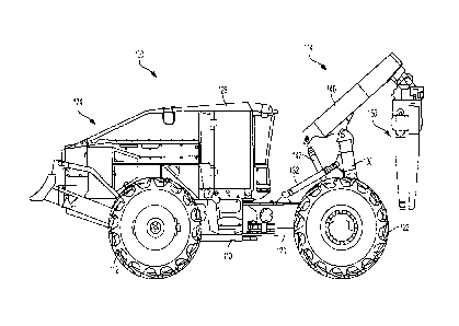
[0016] Figure 1 illustrates an exemplary machine having a pressure
compensated load
sense hydraulic system;
[0017] Figure 2 illustrates an exemplary embodiment of a grapple;
[0018] Figure 3 illustrates some exemplary operator controls for a machine
having a
pressure compensated load sense hydraulic system;
6
CA 02934380 2016-06-28
[0019] Figure 4 is an exemplary schematic for a pressure compensated load
sense
hydraulic system; and
[0020] Figure 5 is an exemplary control flow for an improved pressure
compensated load
sense hydraulic system.
[0021] Corresponding reference numerals are used to indicate corresponding
parts
throughout the several views.
Detailed Description
[0022] The embodiments of the present disclosure described below are not
intended to be
exhaustive or to limit the disclosure to the precise forms in the following
detailed description.
Rather, the embodiments are chosen and described so that others skilled in the
art may
appreciate and understand the principles and practices of the present
disclosure.
[0023] Figure 1 illustrates an example of a work machine, a skidder 100,
having a
pressure compensated load sense hydraulic system. The present disclosure is
not limited,
however, to skidders but also is intended to include other work machines used
in construction,
forestry, agriculture and other industries having a pressure compensated load
sense hydraulic
system. As such, while the figures and forthcoming description may relate to a
wheeled
skidder, it is to be understood that the scope of the present disclosure
extends beyond a
wheeled skidder, and the term "machine" or "work machine" will also be used.
The term
"machine" or "work machine" is intended to be broader and encompass other
vehicles besides
a skidder.
[0024] The machine 100 includes a front vehicle frame 110 coupled to a rear
vehicle
frame 120. Front wheels 112 support the front vehicle frame 110, and the front
vehicle frame
110 supports an engine compartment 124 and an operator cab 126. Rear wheels
122 support
the rear vehicle frame 120, and the rear vehicle frame 120 supports a boom
assembly 114.
The engine compartment 124 houses a vehicle engine or motor, such as a diesel
engine which
provides the motive power for driving the front and rear wheels 112, 122, and
for operating
7
CA 02934380 2016-06-28
the other components associated with the machine 100. The operator cab 126,
where an
operator sits when operating the machine 100, includes a plurality of controls
(e.g., joysticks,
pedals, buttons, etc.) for controlling the machine 100 during operation
thereof
[0025] As shown in Figure 1, the boom assembly 114 includes an arch section
130, a
boom section 140 and a grapple 150. A proximal end of the arch section 130 is
pivotably
coupled to the rear vehicle frame 120 and a distal end of the arch section 130
is pivotably
coupled to the boom section 140. One or more arch hydraulic cylinders 132 are
controllable
by the operator to move the arch 130. A proximal end of the boom section 140
is pivotably
coupled to the arch section 130 and a distal end of the boom section 140 is
pivotably coupled
to the grapple 150. One or more boom hydraulic cylinders 142 are coupled to
the proximal
end of the boom section 140 and are controllable by the operator to move the
boom 140. A
proximal end of the grapple 150 is coupled to the distal end of the boom
section 140.
[0026] An exemplary embodiment of a grapple 150 is shown in Figure 2. The
grapple
150 includes a base 154, left and right tongs 156, 158, and left and right
hydraulic cylinders
166, 168. The base 154 is coupled to the distal end of the boom section 140.
The proximal
ends of the left and right tongs 156, 158 are coupled to the base 154, and the
distal ends of the
left and right tongs 156, 158 are controllable by the left and right hydraulic
cylinders 166, 168
to open and close the grapple 150. The left hydraulic cylinder 166 has a head
end coupled to
the base 154, and a piston end coupled to the proximal end of the left tong
156. The right
hydraulic cylinder 168 has a head end coupled to the base 154, and a piston
end coupled to the
proximal end of the right tong 158. The operator can control extension and
retraction of the
left and right hydraulic cylinders 166, 168 to open and close the grapple 150.
When the left
and right hydraulic cylinders 166, 168 are retracted, the proximal ends of the
left and right
tongs 156, 158 are brought closer together, which pulls apart the distal ends
of the left and
right tongs 156, 158, which opens the grapple 150. When the left and right
hydraulic
cylinders 166, 168 are extended, the proximal ends of the left and right tongs
156, 158 are
pushed apart, which brings together the distal ends of the left and right
tongs 156, 158, which
closes the grapple 150. Thus in this embodiment, the operator can retract the
left and right
8
CA 02934380 2016-06-28
tong cylinders 166, 168 to open the grapple 150 to surround a payload (e.g.
trees or other
woody vegetation), and then extend the left and right tong cylinders 166, 168
to close the
grapple 150 to grab, hold and lift the payload so the machine 100 can move it
to another
desired location.
[0027] Figure 3 illustrates an example of operator controls 300 for the
arch, boom and
tong hydraulic cylinders 132, 142, 166, 168. The operator controls 300 include
a boom
control 302, an arch control 304 and a grapple control 306. The boom control
302 controls
extension and retraction of the boom hydraulic cylinders 142 to move the boom
140. The
arch control 304 controls extension and retraction of the arch hydraulic
cylinders 132 to lower
and raise the arch 130. The grapple control 306 controls extension and
retraction of the tong
hydraulic cylinders 166, 168 to open and close the grapple 150. The boom, arch
and grapple
controls 302, 304, 306 send electrical signals to an electrical controller 310
and the controller
310 sends command signals to control the boom, arch and tong hydraulic
cylinders 142, 132,
166, 168 over control lines 320.
[0028] Figure 4 is a schematic of an exemplary pressure compensated load
sense
hydraulic system 400 for the arch, boom and tong hydraulic cylinders 132, 142,
166, 168.
The hydraulic system 400 includes a hydraulic pump 402, a load sense relief
valve 404, a
fluid reservoir 406, a load sense drain orifice 408, a boom spool valve 412,
an arch spool
valve 414, a grapple spool valve 416, a boom pressure compensator 422, an arch
pressure
compensator 424, a grapple pressure compensator 426, a boom load check valve
432, an arch
load check valve 434, and a grapple load check valve 436. The command signals
sent by the
controller 310 control the positions of the boom, arch and grapple spool
valves 412, 414, 416.
The pump 402 hydraulically powers the arch 130, boom 140 and grapple 150.
[0029] The boom, arch and grapple spool valves 412, 414, 416 are shown as
electrically
controlled, closed center, proportional control valves. Electrically
controlled solenoids can be
used to shift the spool valves 412, 414, 416, where the solenoids are
proportional and
therefore can be varied to change the stroke of the spool valves 412, 414,
416. The more
electrical current commanded to one of the solenoids, the more each respective
spool valve
9
CA 02934380 2016-06-28
412, 414, 416 will stroke. The boom, arch and grapple pressure compensators
422, 424, 426
are shown as proportional and therefore can vary the flow. The boom, arch and
grapple
pressure compensators 422, 424, 426 are shown downstream of the boom, arch and
grapple
spool valves 412, 414, 416 to represent a post-compensated hydraulic load
sense system. The
improvement to the pressure compensated load sense hydraulic system can be
used in both
post-compensated and pre-compensated load sense systems. When one of the
solenoids is
electrically commanded on, and the associated spool valve 412, 414, 416 shifts
to allow flow
from the pump 402 to its respective hydraulic function cylinder, the passage
through the spool
valve 412, 414, 416 from the pump inlet side to the associated pressure
compensator 422, 424,
426 is effectively a variable metering orifice. The variable metering orifice
is commonly
referred to as the inlet metering orifice. As the spool valve 412, 414, 416
strokes more, the
open area of this inlet metering orifice becomes larger. The larger the open
area of the
metering orifice, the larger the flow rate through the spool valve 412, 414,
416 at a given
pressure drop.
[0030] A pump outlet line 452 hydraulically couples the pump 402 to the
boom, arch and
grapple spool valves 412, 414, 416. A reservoir line 456 hydraulically couples
the boom, arch
and grapple spool valves 412, 414, 416 to the reservoir 406. The boom spool
valve 412
controls flow between the pump 402 and the boom hydraulic cylinder 142, and
between the
boom hydraulic cylinder 142 and the reservoir 406 to control raising and
lowering of the
boom 140. The arch spool valve 414 controls flow between the pump 402 and the
arch
hydraulic cylinder 132, and between the arch hydraulic cylinder 132 and the
reservoir 406 to
control raising and lowering of the arch 130. The grapple spool valve 416
controls flow
between the pump 402 and the grapple hydraulic cylinders 166, 168, and between
the grapple
hydraulic cylinders 166, 168 and the reservoir 406 to control opening and
closing of the
grapple 150.
[0031] A load sense circuit 454 hydraulically couples a hydraulic control
of the pump
402, the load sense relief valve 404, the load sense drain orifice 408, the
lower control ports
of the boom, arch and grapple pressure compensators 422, 424, 426, and the
block flow sides
CA 02934380 2016-06-28
of the boom, arch and grapple load check valves 432, 434, 436. The load sense
circuit 454
indicates the highest function load of the arch, boom and tong hydraulic
cylinders 132, 142,
166, 168 that are currently receiving flow from the pump 402 through their
associated spool
valve 412, 414, 416.
[0032] In a scenario when the operator is sending commands using the boom,
arch and
grapple controls 302, 304, 306 to raise the arch and boom 130, 140, and close
the grapple 150,
the controller 310 can send command signals to the solenoids of the boom, arch
and grapple
spool valves 412, 414, 416 to shift the spool valves 412, 414, 416 to the
bottom positions. In
the bottom position, the boom spool valve 412 controls variable flow from the
hydraulic
pump 402 through the lower flow path to the boom pressure compensator 422; and
the boom
pressure compensator 422 controls variable flow through the middle flow path
of the boom
spool valve 412 to retract the boom hydraulic cylinder 142. In the bottom
position, the arch
spool valve 414 controls variable flow from the hydraulic pump 402 through the
lower flow
path to the arch pressure compensator 424; and the arch pressure compensator
424 controls
variable flow through the middle flow path of the arch spool valve 414 to
retract the arch
hydraulic cylinder 132. In the bottom position, the grapple spool valve 416
controls variable
flow from the hydraulic pump 402 through the lower flow path to the grapple
pressure
compensator 426, and the grapple pressure compensator 426 controls variable
flow through
the middle flow path of the grapple spool valve 416 to extend the tong
hydraulic cylinders
166, 168. The load sensed in moving the boom, arch and tong hydraulic
cylinders 142, 132,
166, 168 is communicated back through the middle flow paths of the boom, arch
and grapple
spool valves 412, 414, 416 to the allow flow sides of the boom, arch and
grapple load check
valves 432, 434, 436, respectively. The load sense circuit 454 senses the
highest load
pressure through the boom, arch and grapple load check valves 432, 434, 436.
Those of skill
in the art will realize that if one or more of the hydraulic functions (boom,
arch or grapple
140, 130, 150) is inactive (no flow being commanded), then the respective
spool valve 412,
414, 416 will be in the closed position and the load sense circuit 454 will
not sense the load
pressure from the inactive hydraulic function regardless of its pressure
relative to the other
active hydraulic functions.
11
CA 02934380 2016-06-28
[0033] In this scenario, a pressure balance is performed by the pressure
compensators
422, 424, 426 for each of the active hydraulic functions. The load sense
circuit 454 applies
the highest function load on the bottom side of each of the boom, arch and
grapple pressure
compensators 422, 424, 426 trying to force the respective compensator closed,
and the
individual function's load is applied on the top side of each of the boom,
arch and grapple
pressure compensators 422, 424, 426 trying to force the respective compensator
open. The
compensators of the lower loaded function(s) will be forced closed since the
highest function
load will be higher than the load of the respective function. This added
restriction to the
lower loaded function(s) will make all of the flow paths to the active
hydraulic functions have
equal resistance allowing flow sharing between unequally loaded functions. As
explained
above, although pressure compensation has the benefit of flow sharing, the
pressure
compensators introduce added restriction and loss in power that results in
heat production.
[0034] On some machines (e.g. the skidder 100) with a pressure compensated
load sense
system, the situation of having a large difference between the heaviest and
lightest load can
occur frequently when commanding the grapple 150 closed with constant tong
squeeze to
hold and move a payload. Constant tong squeeze is when the tong close function
is constantly
being activated to provide constant pressure through the tong hydraulic
cylinders 166, 168 on
the tongs 156, 158 in the closing direction. This constant pressure closing
the tongs 156, 158
is necessary to keep a hold of a payload in the grapple 150 when skidding.
Without this
constant force on the tongs 156, 158 to hold the payload, the payload may fall
out of the
grapple 150. When constant tong squeeze is active, the tong hydraulic
cylinders 166, 168 are
stalled out against the payload which causes the pressure in the load sense
circuit 454 to
increase until the load sense relief setting of the load sense relief valve
404 is reached. This
brings the hydraulic pump 402 to maximum system pressure. Therefore when
another
function is cycled, e.g. the arch 130 or boom 140, a large pressure difference
can exist
between the highest load sense produced by the grapple 150 and the load of the
arch 130 or
boom 140. This is particularly the case when the arch 130 or boom 140 is being
lowered.
Lowering the arch 130 or boom 140 is a gravity-aided function and therefore
does not take
much pressure to move. The arch 130 or boom 140 are also functions that
usually require a
12
CA 02934380 2016-06-28
large amount of flow to obtain adequate cycle times. The result of this large
pressure
difference and the flow rate results in a significant power loss generating
heat.
[0035] Since the boom 140, arch 130, and grapple 150 hydraulic functions
are electro-
hydraulically controlled using the controls 302, 304, 306, the controller 310
knows when each
of the boom, arch and tong controls 302, 304, 306 are being used to activate
the boom, arch
and tong hydraulic functions 140, 130, 150. Thus, when the tong control 306 is
being used to
constantly squeeze or close the tongs 156, 158 of the grapple 150, and the
boom or arch
controls 302, 304 are activated to lower the boom or arch 140, 130, the
controller 310 can
suspend the tong close command. When the tong close command is suspended, the
grapple
spool valve 416 is released to the neutral state (middle position) blocking
flow between the
hydraulic pump 402 and the tong hydraulic cylinders 166, 168, and trapping
hydraulic fluid
between the tong spool valve 416 and the tong hydraulic cylinders 166, 168.
Blocking flow
between the hydraulic pump 402 and the tong hydraulic cylinders 166, 168 also
blocks the
load of the tong hydraulic cylinders 166, 168 from the load sense circuit 454.
Since the
hydraulic fluid is trapped between the tong spool valve 416 and tong hydraulic
cylinders 166,
168, the only way to lose squeeze force on the logs is from hydraulic system
leakage or if the
tongs 156, 158 are forced open by some external force causing a tong work port
relief to open
on the tong hydraulic cylinders 166, 168. An external force causing the
cylinder pressure to
reach the work port relief setting on the tong hydraulic cylinders 166, 168 is
possible with or
without the improvement to the pressure compensated load sense hydraulic
system. To
address hydraulic system leakage, since it typically only takes a few seconds
to lower the arch
130 or boom 140, this is usually not enough time for the cylinder pressure of
the tong
hydraulic cylinders 166, 168 to leak down. To help ensure leakage does not
cause the grapple
150 to lose hold of the payload, a suspend timer can be implemented to only
allow the tong
close command to be suspended a certain suspend time period, e.g. 5 seconds.
After the
suspend time period, the tong close command can be reactivated for a
reactivation time
period, e.g. 1 second. As long as the tong close command is still active and
the arch 130 or
boom 140 lower command is still active, this suspend and reactivate process
can be repeated
13
CA 02934380 2016-06-28
by the controller 310 to suspend the tong close command for the suspend time
period and
reactivate the tong close command for the reactivation time period.
[0036] A grapple close or tong squeeze initialization time period can also
be implemented
to help ensure that the grapple 150 is securely closed on the payload held by
the tongs 156,
158 before suspending the tong squeeze command. The tong squeeze
initialization time
period can be set to any desired time, e.g. 10 seconds. The controller 310 can
be configured
to not suspend a tong squeeze command during the initial tong squeeze
initialization time
period that the tong squeeze command is active so that the tongs have an
opportunity to fully
close and grab against the payload. Otherwise, without a proper clamp force on
the payload,
the payload may slip out of the grapple 150 when the machine starts to travel.
So if an arch
130 or boom 140 lower is commanded during the initial tong squeeze
initialization time
period of a tong squeeze command, the controller 310 will not suspend the tong
squeeze
command. After the tong squeeze initialization time period has passed, then it
is assumed that
the tongs 156, 158 have had a chance to fully close against the payload and
the tong squeeze
command can be suspended when an arch 130 or boom 140 lower command is given
by the
operator.
[0037] The following example helps illustrate the potential power savings
of the
improvement to the pressure compensated load sense hydraulic system
illustrated in Figure 4.
Assume that the load sense relief valve 404 has a load sense relief setting of
2700 psi (pounds
per square inch) which means that the load sense circuit 454 will be limited
to 2700 psi.
Assume also that the load sense margin of the pump 402 is set to 300 psi. The
outlet pressure
produced by the pump 402 will equal the load sense pressure plus the pump load
sense
margin. Therefore in this example, the maximum system pressure will be 3000
psi. Also
assume that the bias springs for the pressure compensators 422, 424, 426 are
negligible in
force and that plumbing losses are negligible as well. Lastly, assume that the
pressure
required to lower the arch 130 is 500 psi, the flow requirement to lower the
arch 130 is 50
GPM (gallons per minute), and the pump 402 is adequately sized to provide a
flow of 50
GPM.
14
CA 02934380 2016-06-28
[0038] The above assumptions will be used for the load sensing hydraulic
system 400
without the improvement in the situation where the operator is commanding a
constant tong
squeeze for the grapple 150, and the operator is commanding a lowering of the
arch 130.
With constant tong squeeze for the grapple 150 active, the controller 310 will
send control
signals to the solenoid of the grapple spool valve 416, shifting the grapple
spool valve 416
open to allow the pump 402 to flow hydraulic fluid to the head end of the tong
cylinders 166,
168, closing the tongs 156, 158 around a payload, e.g. logs or other material.
Once the tongs
156, 158 are fully closed against the payload, the tong cylinders 166, 168
will be stalled
which will cause the load sense circuit 454 to reach the load sense relief
limit of 2700 psi.
The outlet pressure of the pump 402 will be equal to the highest load sense
signal (2700 psi
from the tong cylinders 166, 168) plus the load sense margin (300 psi) which
is 3000 psi. The
load sense pressure on the bottom side of the arch compensator 424 will be the
highest load
sense pressure of 2700 psi. This load sense pressure of 2700 psi will force
the arch
compensator 424 to the closed position. When the operator activates lowering
of the arch 130
using the arch control 304 to a full (100%) lowering command, the controller
310 will send
control signals to the solenoid of the arch spool valve 414, shifting the arch
spool valve 414 to
full stroke. With the arch spool valve 414 shifted, the outlet pressure (3000
psi) of the pump
402 will initially be seen at the top side of the arch compensator 424. With
pump outlet
pressure (3000 psi) on the top side and load sense pressure (2700 psi) on the
bottom side of
the arch compensator 424, the arch compensator 424 will open allowing flow to
the arch
cylinder 132. Once the arch compensator 424 is open, the pressure upstream of
the arch
compensator 424 will initially want to drop to the pressure it takes to lower
the arch 130
which is 500 psi. But once the pressure upstream of the arch compensator 424
is lowered to
the highest load sense pressure of 2700 psi, the arch compensator 424 will
start to close. The
arch compensator 424 will then restrict flow to the arch cylinder 132 such
that the pressure
upstream of the arch compensator 424 will be equal to the highest load sense
pressure creating
a pressure balance on each side of the arch compensator 424. This means that
the pressure
upstream of the arch compensator 424 will be equal to 2700 psi resulting in a
300 psi drop
across the inlet metering orifice in the arch spool valve 414 (3000 psi - 2700
psi = 300 psi).
CA 02934380 2016-06-28
The inlet metering orifice in the arch spool valve 414 can be designed such
that there will be
300 psi drop at 50 GPM at full stroke. The arch compensator 424 will then have
the highest
load sense pressure of 2700 psi upstream and the arch lower load of 500 psi
downstream
which results in a 2200 psi pressure drop across the arch compensator 424 at
50 GPM. Using
the above fluid power equation, Power = P * Q / 1714, calculates a power loss
of
approximately 64 HP going straight to heat in this particular example.
[0039] The same assumptions and situation will now be used for the load
sensing
hydraulic system 400 with the improvement, which will suspend the constant
tong squeeze
command when the arch 130 or boom 140 is being lowered. With constant tong
squeeze for
the grapple 150 active, the controller 310 sends control signals to the
solenoid of the grapple
spool valve 416, shifting the grapple spool valve 416 open to continuously
supply flow of
hydraulic fluid towards the head end of the tong cylinders 166, 168, closing
the tongs 156,
158 around a payload. After a tong squeeze initialization time period (e.g. 10
seconds) to
ensure that the tongs 156, 158 are fully closed around the payload, the
controller 310
determines the tong cylinders 166, 168 are stalled and suspends the tong
squeeze command
when lowering of the arch 130 or boom 140 is active. When lowering of the arch
130 is
commanded using the arch control 304, the controller 310 will send control
signals to the
solenoid of the arch spool valve 414, shifting the arch spool valve 414 to
lower the arch 140.
When the controller 310 sends the control signals to the solenoid of the arch
spool valve 414,
the controller 310 will stop sending the control signals to the solenoid of
the grapple spool
valve 416 which allows the grapple spool valve 416 to return to its neutral
position blocking
flow between the hydraulic pump 402 and the tong cylinders 166, 168 through
the grapple
spool valve 416, which also blocks the load of the tong cylinders 166, 168
from the load sense
circuit 454. With the grapple spool valve 416 closed, the maximum load sense
signal will be
the 500 psi load coming from the arch cylinder 132. Thus, the pressure
upstream of the arch
compensator 424 will equal the highest load sense signal. So the pressures
upstream and
downstream of the arch compensator 424 will both be 500 psi, and therefore
there will
essentially be no pressure drop or heat production across the arch compensator
424. So in this
example, 64 HP of heat generation will be saved. When the operator stops
commanding
16
CA 02934380 2016-06-28
lowering of the arch 130, the controller 310 will no longer see the arch
lowering command
from the arch control 304 and will restart sending control signals to the
solenoid of the
grapple spool valve 416 to shift the grapple spool valve 416 open to direct
flow of hydraulic
fluid towards the head end of the tong cylinders 166, 168. This opens pump
flow to the tong
cylinders 166, 168, and also opens load pressure from the tong cylinders 166,
168 into the
load sense circuit 454, allowing the outlet pressure of the pump 402 to reach
the highest load
sense signal plus pump margin and a constant squeeze will again be applied on
the payload in
the grapple 150.
[0040] Figure 5 shows an example of a more general control flow 500 for an
improved
pressure compensated load sense hydraulic system with at least two hydraulic
functions. At
block 502 the system determines whether a first hydraulic function (HF1) is
stalled. This can
be done by waiting a predetermined initialization time period or by other
methods. The
system waits at block 502 until it determines that a first hydraulic function
(HF1) is stalled.
When the system determines that HF1 is stalled, control proceeds to block 504.
[0041] At block 504 the system checks if an operator command is being
issued by an
operator control to activate another hydraulic function (HF2). If no operator
commands are
being issued to activate another hydraulic function, control goes back to
block 502. If
operator commands are being issued to activate another hydraulic function
(HF2), control
proceeds to block 506.
[0042] At block 506, the system sends command signals to activate HF2 and
to suspend
HF1, which blocks flow to and from HF1 and also removes the load of HF1 from
the pump.
At block 508 the system starts a suspend timer to track a suspend time period
for HF1.
Control then proceeds to block 510.
[0043] At block 510 the system checks if operator commands are still being
issued by an
operator control for HF2. If operator commands are no longer being issued to
activate HF2,
the system reactivates HF1 at block 512, and control returns to block 502. If
operator
commands are still being issued to activate HF2, control proceeds to block
514.
17
CA 02934380 2016-06-28
[0044] At block 514 the system checks if operator commands are still being
issued by an
operator control for HF1. If operator commands are no longer being issued to
activate HF1,
control returns to block 502. If operator commands are still being issued to
activate HF1,
control proceeds to block 516.
[0045] At block 516 the system checks if the suspend time period for HF1
has passed. If
the suspend time period for HF1 has passed, the system reactivates HF1 and
starts a
reactivation timer at block 518 to track a reactivation time period for HF1,
and then control
proceeds to block 520. If the suspend time period for HF1 has not passed,
control returns to
block 510.
[0046] At block 520 the system checks if operator commands are still being
issued by an
operator control for HF2. If operator commands are no longer being issued to
activate HF2,
the control returns to block 502. If operator commands are still being issued
to activate HF2,
control proceeds to block 522.
[0047] At block 522 the system checks if operator commands are still being
issued by an
operator control for HF1. If operator commands are no longer being issued to
activate HF1,
control returns to block 502. If operator commands are still being issued to
activate HF1,
control proceeds to block 524.
[0048] At block 524 the system checks if the reactivation time period for
HF1 has passed.
If the reactivation time period for HF1 has passed, control passes to block
526 where the
system suspends HF1, and then returns to block 508 to restart the suspend
timer. If the
reactivation time period for HF1 has not passed, control returns to block 520.
[0049] While the disclosure has been illustrated and described in detail in
the drawings
and foregoing description, such illustration and description is to be
considered as exemplary
and not restrictive in character, it being understood that illustrative
embodiment(s) have been
shown and described and that all changes and modifications that come within
the spirit of the
disclosure are desired to be protected. It will be noted that alternative
embodiments of the
present disclosure may not include all of the features described yet still
benefit from at least
18
CA 02934380 2016-06-28
some of the advantages of such features. Those of ordinary skill in the art
may readily devise
their own implementations that incorporate one or more of the features of the
present
disclosure and fall within the spirit and scope of the present invention as
defined by the
appended claims.
19