Note: Descriptions are shown in the official language in which they were submitted.
CA 02934753 2016-06-21
WO 2015/101603 PCT/EP2014/079378
1
DEVICE AND METHOD FOR CONTROLLING DEPOSIT FORMATION
FIELD OF THE INVENTION
The invention relates to the deposit control in water bearing systems,
particularly in open
recirculating cooling water systems.
BACKGROUND
Open recirculating cooling water systems are widely used processes for
rejection of waste
heat from a variety of industrial processes. Such systems are open as water
e.g. evaporates
at the cooling tower. In addition, controlled removal of recirculating water
is necessary to limit
the accumulation of dissolved species that cause corrosion, scaling and
fouling. The effluent
water is rernnveri with the so-called "blowdown stream''.
Various additives are on the market that can be added to the recirculating
water in order to
specifically avoid corrosion, scaling or fouling. These additives are normally
fed at a feeding
rate needed to maintain a relatively constant concentration in the
recirculating water. The
feeding rate is typically controlled to replace the amount of the additives
that are consumed
within the recirculating system and that are removed with the blowdown stream.
However, This type of deposit control is static and cannot properly react when
the
composition of the recirculating water changes unexpectedly. Such unexpected
changes can
have various causes. For example, the temperature and thus also the
composition of the
fresh water (makeup water) that is added to the system varies over the year.
Various attempts have been made to monitor the properties of the recirculating
water in order
to better understand the processes taking place and to properly react in case
of unexpected
events. All these attempts rely on the monitoring of one or more key operation
indicators
such as pH value of the recirculating water, electrical conductivity of the
recirculating water,
concentration of anti-deposit additives in the recirculating water.
CA 02934753 2016-06-21
WO 2015/101603 2 PCT/EP2014/079378
Based upon the measured values of these key operation indicators, conclusions
are drawn in
respect of the current tendency of the recirculating water to form deposits.
If necessary,
counter measures are initiated that are believed to be appropriate, such as
increasing the
dosage of a particular anti-deposit additive. Attempts have also been made to
simultaneously
monitor a plurality of key operation indicators in order to base the initiated
counter measure
on a broader basis of data.
However, key operation indicators such as pH value, electrical conductivity,
and the like are
not directly linked to deposit formation. Even if electrical conductivity and
pH value are stable
over time, undesired scaling may occur. Ongoing processes may compensate one
another.
For example, when the pH value is decreased for some reason, this may lead to
an increase
of the concentration of e.g. basic CaCO3 in the recirculating water thus
increasing the pH
value again. Furthermore, a sudden change of the pH value, for example, can
have various
reasons. The pump that supplies acid or base to the recirculating water may be
broken, the
pH meter may be broken, the storage tank containing acid, base or buffer may
be empty, and
the like. Therefore, a key operation indicator may change for various reasons
that all have
the same consequence of undesired deposit formation.
US 2009/0277841 discloses a process for operation of evaporative recirculating
cooling
systems. In addition to reducing the scaling and corrosive tendencies of the
water, the
method is said to eliminate or reduce discharge from the system without
creating any
localized corrosive or scaling conditions as a result of the treatment
process. The described
measurement and control system generally comprises an array of measurements, a
means
of implementing control logic, and an array of control actions including
activating an ion
exchange device to treat makeup water. Preferably, the measurements include
one or more
of pH, conductivity, hardness, alkalinity, corrosiveness, scaling tendency,
treatment additive
dosage level, and treatment additive residual of the makeup, treated makeup,
and
recirculating water.
US 2010/0176060 and US 2013/0026105 disclose the control of scaling in a
cooling water
system with CO2 based upon measurements of the cooling water's pH, alkalinity
and Ca2+
concentration.
A further problem is that the formation of certain deposits is irreversible.
This is particularly
the case for scaling. While sophisticated anti-scaling additives are available
on the market
that are capable of effectively avoiding the deposition of the scaling on
surfaces at
appropriate dosages, they are usually not capable of removing the scaling once
it has been
3
deposited. Inconsequence, the dosage of anti-scaling additives in the
recirculating water
is typically kept higher than really necessary in order to avoid scaling
formation, just to
ensure that no scaling is irreversibly formed.
SUMMARY OF THE INVENTION
There is a demand for methods to control deposit formation, in particular
scaling, in water
bearing systems and to initiate appropriate countermeasures that have
advantages
compared to the methods of the prior art.
The object of the present invention is solved by a method for controlling
deposit
formation in a liquid bearing system comprising a main system and a subsystem,
wherein a liquid is transported inside the main system and/or the subsystem,
the
method comprising the step of altering a property of the liquid inside the
subsystem
such that it differs from the property of the liquid inside the main system in
a manner
that deposit formation inside the subsystem is more promoted than inside the
main
system.
In a broad aspect, moreover, the present invention provides a method for
controlling
deposit formation in a liquid bearing system comprising a main system and a
subsystem, wherein the liquid is transported inside the main system and the
subsystem,
wherein the subsystem is designed as a bypass, the method comprising the step
of
altering a first flow velocity of the liquid inside the subsystem such that
the first flow
velocity is greater than a second flow velocity inside the main system,
wherein the first
flow velocity inside the subsystem is mainly realized by a pumping device
inside the
subsystem, and wherein the subsystem is configured such that the liquid
transported
inside the subsystem has a Reynolds number greater than 8,000, and wherein the
deposit formation is detected by a detection device inside the subsystem and
treating
the liquid bearing system with a treatment chemical once the deposit inside
the
subsystem is detected thereby preventing deposit formation in the main system.
In another broad aspect, the present invention provides a device for
controlling deposit
formation in a liquid bearing system comprising a main system and a subsystem
being
designed as a bypass; a pumping device disposed within the subsystem; and a
detection device disposed within the subsystem, wherein a liquid is
transportable inside
CA 2934753 2021-06-16
3a
the main system and subsystem, wherein the pumping device is configured for
increasing the velocity of the volume flow of the liquid in the subsystem,
wherein the
volume flow of the liquid within the subsystem is higher by at least 0.01
m/sec than the
volume flow of the liquid in the main system, wherein deposit formation inside
the
subsystem is more promoted than inside the main system, and wherein the
deposit
formation can be detected by the detection device; and wherein the subsystem
is
configured such that liquid transported inside the subsystem has a Reynolds
number
greater than 8,000; and a means for adding a treatment chemical to the liquid
bearing
system.
In another broad aspect, the present invention provides an upgrade kit for a
liquid
bearing system comprising: a) a subsystem designed as a bypass, wherein the
subsystem has access to the liquid of the liquid bearing system; b) a pumping
device c)
a device configured to detect the formation of a deposit inside the subsystem;
wherein a
volume flow of the liquid inside the subsystem leaving the pumping device has
a first
velocity, wherein the first velocity is greater than a second velocity
representing the
volume flow of the liquid in the water bearing system, and wherein the
subsystem is
configured such that liquid transported inside the subsystem has a Reynolds
number
greater than 8,000; and d) a means for adding a treatment chemical to the
liquid bearing
system.
It is herewith advantageously possible to use the subsystem as a watchdog or
as an
early warning system, because it has been surprisingly found that artificial
process
conditions can be established that promote deposit formation, i.e. that are
harsher
process conditions with respect to deposit formation. Thus, the liquid that is
processed
under such harsher process conditions tends to form deposits, in particular
scaling,
inside the subsystem ahead of the recirculating liquid that is processed under
the
current operational conditions of the liquid bearing system inside the main
system. Such
a method may ensure that a proper countermeasure is initiated before deposit
formation
inside the main system of the liquid bearing system even starts. In
particular, the main
system and the subsystem are configured such that the liquid has access to
both the
main system and the subsystem. As a result the concentration of a treatment
chemical
inside the subsystem is the same as the concentration of the treatment
chemical inside
CA 2934753 2021-06-16
3b
the main system advantageously. The treatment chemical may be configured such
that
the treatment chemical comprises antideposit components. Moreover it is
provided that
the liquid is recirculated inside the liquid bearing system. Preferably the
liquid comprises
water and the liquid bearing system comprises a cooling tower or a tank.
Deposits are
for example scale, fouling and/or corrosion products such as iron oxides. In
particular
the treatment chemical comprises antisling products, antifouling products
and/or
anticorrosion products. Furthermore it is provided that the countermeasure is
adapted to
the kind of deposit. As a consequence the composition of the treatment
chemical may
be adapted to the kind of deposit. For example the treatment chemical
comprises an
CA 2934753 2020-01-10
CA 02934753 2016-06-21
4
WO 2015/101603 PCT/EP2014/079378
antifouling component that reduces the specific fouling detected inside the
subsystem. It is
also thinkable that the chemical treatment is fed to the liquid bearing system
at a feeding
rate, wherein the feeding rate depends on the type of the deposit. In
particular it is thinkable
that the treatment chemical is fed to the liquid bearing system in a
continuous or pulsed form.
Moreover it is provided that treatment chemicals are fed to the liquid bearing
system all the
time, wherein the composition of the treatment chemical is changed as soon
deposit
formation is detected inside the subsystem. Further it has been surprisingly
found that the
artificial process conditions can be adjusted over a broad range so that
different degrees of
harshness are possible. In consequence, a buffer between the harsher
conditions in the
bypass and the current conditions in the operational water bearing system can
be freely
adjusted to allow for a comparatively early or for a comparatively late
initiation of counter
measure, respectively. It is also conceivable that the deposit formation is
derived from
detecting a key operation indicator such as pH value, electrical conductivity
and the like.
Furthermore it is provided that the pipes of the main system and the subsystem
are made
from the same material.
In another embodiment of the present invention it is provided that the
subsystem comprises a
detection device for detecting the deposit formation. Consequently it is
advantageously
possible to detect a key performance indicator directly. For the purpose of
the specification, a
key performance indicator according to the invention is a property that is
directly linked to the
presence or absence of a deposit, particularly corrosion, scaling, and/or
fouling. It has been
surprisingly found that deposit control can be substantially improved when it
is not based on
monitoring of key operation indicators such as the pH-value, but on monitoring
of key
performance indicators instead, namely deposit formation, as corrosion,
scaling and fouling
for instance. It is principally also possible to get information about a key
performance
indicator by measuring the temperature, in particular its heat transfer
coefficient, of a material
that is exposed to the water bearing system such that a deposit may be formed
on its
surface. For example, it is known that measuring the temperature or more
precisely the heat
transfer coefficient at various locations of a heat exchanger may provide
information about
deposit formation due to changes of heat capacity and thermal conductivity.
Key
performance indicators, i.e. deposits, may be detected by various means, e.g.
optically,
electrically, mechanically or with X-rays. It is also thinkable that the
subsystem is configured
such that the subsystem may be uncoupled from the main system. Subsequently
the
subsystem is examined for deposit formation and/or type of the deposit without
stopping the
operation of the main system advantageously.
In another embodiment it is provided that the subsystem is a bypass. It has
been surprisingly
CA 02934753 2016-06-21
WO 2015/101693 PCT/EP2014/079378
found that the monitoring of key performance indicators can advantageously be
performed in
a bypass wherein artificial process conditions that promote deposit formation
are set inside
the bypass. Once a significant change of key performance indicators is
detected under the
artificial conditions within the bypass, e.g. the beginning of scaling,
appropriate
5 countermeasures may be initiated, e.g. by increasing the dosage of anti-
scaling additive. As
the environment in the bypass is more favorable for deposit formation than in
the main
system, scaling has not yet begun in the main system and can thus be
effectively prevented.
This has particularly advantageous with respect to scaling which can usually
not be removed
by means of anti-scaling additives once it has been deposited on a surface.
Preferably, the
condition of the liquid, in particular of recirculating water, in the bypass
differs from the
condition of the liquid in the main system. Preferably, the temperature and/or
the flow velocity
of the recirculating water in the bypass is/are higher than that of the
recirculating water in the
main system.
In another embodiment of the present invention it is provided at least one
property of the
liquid inside the subsystem is manipulated by a manipulation device.
Preferably the liquid
inside the subsystem and the liquid in the main system have only one non-
equivalent
property. As a consequence the subsystem represents the main system as closely
as
possible advantageously. Furthermore, it has been surprisingly found that
artificial process
conditions can be established without substantially altering the thermal
conditions of the
system. In particular, it has been surprisingly found that the temperature of
the recirculating
water in the bypass does not need to be changed compared to the temperature of
the
recirculating water in the operational water bearing system.
In another embodiment of the present invention it is provided that liquid
inside the subsystem
is configured such that a Reynolds number of the liquid inside the subsystem
is greater than
8,000 and preferably between 10,000 and 20,000. It has been surprisingly found
that the
deposit formation will be accelerated, if the Reynolds number is greater
inside the subsystem
than inside the main system and the Reynolds number inside the subsystem is
greater than
8,000 and preferably between 10,000 and 20,000. Preferably, the stream inside
the bypass
is not laminar but turbulent, whereas the stream in main system is not
turbulent but laminar.
Typically the Reynolds number depends on the density, the viscosity, the flow
velocity and
the dimensions of the liquid.
In another embodiment of the present invention it is provided that a first
flow velocity of the
liquid inside the subsystem is configured such that the first flow velocity
inside the subsystem
is greater than a second flow velocity inside in the main system. Preferably
the volume flow
CA 02934753 2016-06-21
WO 2015/101603 6
PCT/EP2014/079378
of the liquid in the bypass is higher than that of the liquid in the main
system. Preferably, the
volume flow or the first velocity in the bypass is higher by at least 0.01
m/sec, more
preferably by at least 0.05 m/sec, still more preferably by at least 0.1
m/sec, yet more
preferably by at least 0.15 m/sec., most preferably by at least 0.2 m/sec, and
in particular by
at least 0.25 m/sec than the flow velocity of the liquid in the main system.
Preferably, the
temperature of the recirculating water in the bypass does not significantly
differ from the
temperature of the recirculating water in the operational water bearing
system. Preferably,
the temperature difference is not more than 1 C, more preferably not more than
0.5 C, most
preferably not more than 0.2 C.
In another embodiment of the present invention it is provided that the first
flow velocity inside
the subsystem is mainly realized by a pumping device. In particular the flow
velocity may
easily be adjusted by a suitable pump inside the bypass. It has been
surprisingly found that
the kinetic energy entrained by the pump in order to increase the first flow
velocity of the
liquid in the bypass is much lower than the energy that would otherwise be
entrained by
increasing the water temperature in the bypass. In a preferred embodiment it
is provided to
manipulate the flow velocity by hydrostatic or hydrodynamic means. In
particular a
hydrostatic, hydrodynamic or atmospheric pressure of the main system is only
used for
acceleration. Thus, when guiding the recirculating water through the bypass at
an elevated
flow velocity but constant temperature, the thermodynamic conditions inside
the bypass are
very similar to the thermodynamic conditions in the operational water bearing
system. Thus
the current situation in the main system is very closely reflected by the
current situation in the
bypass at favored conditions with respect to deposit formation.
In a preferred embodiment of the present invention it is provided that the
deposit formation is
detected by means of ultrasound, wherein an ultrasonic signal is emitted and a
reflected
ultrasonic signal is detected. Preferably the measurement provides information
about the
thickness and/or composition of the deposit. Suitable methods and devices to
measure key
performance indicators by means of ultrasound are known from the prior art.
These methods
and devices preferably also monitor the temperature so that additional
conclusions can be
drawn from the temperature values.
In particular it is provided that the deposit is detected by a device, for
detecting deposits in a
reflection area inside a liquid-bearing system comprising an ultrasonic
transducer for emitting
an ultrasonic emission signal towards the reflection area and a first
detection means for
detecting an ultrasonic reflection signal obtained by reflection of the
ultrasonic emission
signal in the reflection area, wherein a second detection means is disposed in
the reflection
CA 02934753 2016-06-21
7
WO 2015/101603 PCT/EP2014/079378
area, the second detection means being configured to detect a specific kind of
deposit. It is
also possible to detect the deposit by a method for detecting fouling and/or
scaling deposits
in a reflection area inside the liquid-bearing system, comprising a first step
of emitting the
ultrasonic emission signal towards the reflection area by an ultrasonic
transducer, a second
step of detecting an ultrasonic reflection signal obtained by reflection of
the ultrasonic
emission signal in the reflection area by first detection means and a third
step of detecting a
specific kind of deposit by a second detection means disposed in the
reflection area. It is
herewith advantageously possible to identify the type or kind or composition
of the deposit
and subsequently adapt the treatment chemical to the kind of deposit.
In another preferred embodiment it is provided that the deposit formation
inside the
subsystem is detected by one of the methods disclosed in WO 2009/141 135.
Preferably the
deposit formation is detected by a method for a high precision measurement of
a
characteristic of a fouling and/or scaling deposit inside a fluid pipe or of a
characteristic of a
portion of the wall inside a fluid pipe, wherein an ultrasonic transducer is
used, wherein a
reflection area is provided in a portion of the wall or attached to a portion
of the wall of the
fluid pipe at a location substantially opposite of the ultrasonic transducer,
wherein the method
comprises the steps of:
a) emitting an ultrasonic emission signal by means of the ultrasonic
transducer and
b) measuring the distance between the ultrasonic transducer on the one hand
and a
fluid/deposit interface or a fluid/wall interface on the other hand in an
absolute distance
measurement by means of evaluating the time-domain reflective signal of the
fluid/deposit or
fluid/wall interface,
wherein the fluid/deposit or fluid/wall interface is either the interface of
the fluid with the
deposit on the reflection area or the interface of the fluid with the wall in
the reflection area,
wherein the time-domain resolution power is 1 ns or less than 1 ns_ Preferably
the deposit is
detected by one of the devices disclosed in WO 2009/141 135. In particular it
is disclosed a
device for a high precision measurement of a characteristic of a fouling
and/or scaling
deposit inside a fluid pipe or of a characteristic of a portion of the wall
inside a fluid pipe,
.. wherein the device comprises an ultrasonic transducer, wherein the device
further comprises
a reflection area in a portion of the wall or attached to a portion of the
wall of the fluid pipe at
a location substantially opposite of the ultrasonic transducer, wherein the
distance between
the ultrasonic transducer on the one hand and a fluid/deposit interface or a
fluid/wall interface
on the other hand is measured in an absolute distance measurement by means of
evaluating
the time-domain reflective signal of the fluid/deposit or fluid/wall
interface, wherein the
fluid/deposit or fluid/wall interface is either the interface of the fluid
with the deposit on the
reflection area or the interface of the fluid with the wall in the reflection
area, wherein the
CA 02934753 2016-06-21
W02015/101603 8
PCT/EP2014/079328
time-domain resolution power of the device is 1 ns or less than 1 ns.
In another preferred embodiment of the present invention it is provided that
the deposit inside
the subsystem is detected by one of the methods disclosed in WO 2013 / 092
819. In
particular the method for detecting deposit formation comprises a method for
detecting and
analyzing deposits on the reflecting area, in particular inside the liquid-
bearing system,
comprising the steps of:
¨ emitting the ultrasonic emission signal towards the reflecting area by an
ultrasonic
transducer in a further first step;
¨ detecting an ultrasonic reflection signal obtained by reflection of the
ultrasonic emission
signal in the area of the reflecting area by detection means in a further
second step;
¨ determining a distribution of the run time of the detected ultrasonic
reflection signal in
response to a specified variable in a further third step;
analyzing the distribution in a fourth step in order to determine if deposits
are deposited
.. at least partially onto the reflecting area. WO 2013/092819 also discloses
devices for
detecting and analyzing deposits in a reflecting are. These devices may be
attached to the
subsystem in order to detect deposit formation. Preferably the device
comprises an
ultrasonic transducer for emitting an ultrasonic emission signal towards the
reflecting area, a
detection means for detecting an ultrasonic reflection signal obtained by
reflection of the
ultrasonic emission signal in the area of the reflecting area and an analyzing
unit for
determining a distribution of the run 5 time of the detected ultrasonic
reflection signal in
response to a specified variable and for analyzing the distribution in order
to determine if
deposits are deposited at least partially onto the reflecting area.
.. In another particularly preferred embodiment of the present invention the
deposit formation is
detected by one of devices disclosed in WO 2013/092820_ In particular the
device for
detecting the deposit comprise a device for detecting deposits in a reflecting
area inside a
liquid-bearing system comprising an ultrasonic transducer for emitting an
ultrasonic 5
emission signal towards the reflecting area and a detection means for
detecting an ultrasonic
reflection signal obtained by reflection of the ultrasonic emission signal in
the area of the
reflecting area, wherein the device further comprises a heater for increasing
the temperature
of the reflecting area. WO 2013/092820 also discloses a method for detecting
fouling and/or
scaling deposits in a reflecting area, in particular inside a liquid-bearing
system, comprising a
step of emitting an ultrasonic emission signal towards the reflecting area by
an ultrasonic
transducer and a step of detecting an ultrasonic reflection signal obtained by
reflection of the
ultrasonic emission signal in the area of the reflecting area by detection
means, wherein the
temperature of the reflecting area is increased by the heater. Preferably the
deposit is
CA 02934753 2016-06-21
9
W02015/191603 PCT/EP2014/079378
measured by one of the methods disclosed in WO 2013/092820.
In a preferred embodiment of the present invention it is provided that the
concentration of the
treatment chemicals inside the liquid bearing system is continuously or
stepwise decreased,
in particular following a mathematical function. In particular the decrease
continues till
deposit formation is detected inside the subsystem. Furthermore it is provided
that the
concentration of the treatment chemicals inside the liquid bearing system is
manipulated, in
particular decreased, every time interval, wherein the time interval
corresponds to a dwell
time. Preferably the dwell time is set by basic parameters describing the
liquid bearing
system such as the total volume of the liquid inside the liquid bearing system
and the loss of
liquid during the running of the liquid bearing system. In particular it is
provided that the
concentration of the treatment chemical inside the liquid bearing system is
regulated by
manipulating the amount of treatment chemicals and/or liquid being fed to the
liquid bearing
system in order to compensate the loss of treatment chemicals and/or liquid
during running
the liquid bearing system. Furthermore it is provided That the concentration
of the treatment
chemical, in particular an antiscaling product, inside the liquid bearing
system is increased as
soon a deposit formation inside the subsystem is detected. Preferably the
amount of
treatment chemicals fed to the liquid bearing system is a multiple, in
particular the double, of
the amount of treatment chemicals that were fed to the liquid bearing system
in a previous
time interval. Furthermore it is provided that the concentration of the
treatment chemical
inside the liquid bearing system is decreased again after the concentration of
the treatment
chemical was decreased in the previous time interval.
In another embodiment of the present invention it is provided that the
temperature inside the
subsystem is monitored. In particular the temperature at the wall of the pipe
guiding the liquid
through the bypass is monitored. The temperature may be used for controlling
the
temperature inside the subsystem positively. It is also thinkable that the
detected
temperature may indicate the deposit formation.
In another embodiment of the present invention it is provided that the
subsystem comprises a
heater. Such a heater may heat the liquid in the subsystem. As a result it is
advantageously
possible to simulate the thermodynamic condition of a part of the main system
being far
away from the subsystem, wherein the liquid inside the part of the main system
has a higher
temperature than the liquid inside an unheated subsystem. Such parts of the
main system
are for example parts of the main system that are responsible for a heat
exchange. The
temperature of the part of the main system being far away from the subsystem
favors deposit
formation inside the part of the main system compared to those parts of the
main system
CA 02934753 2016-06-21
WO 2015/101603 10
PCT/EP2014/079378
having a lower temperature. Equalizing the thermodynamic conditions of the
liquid inside the
subsystem and inside the part of the main system being far away from the
substrate may
guarantee that the subsystem even operates as an early warning system for
parts of the
main system that are usually favored for deposit formation.
In another embodiment of the present invention it is provided that the liquid
bearing system
comprises a device for monitoring the temperature at a wall of a pipe, wherein
the liquid is
guided by the pipe, wherein the device for monitoring the temperature at the
wall of the pipe
comprises a first mean for measuring a first temperature at a first spot and a
second mean
for measuring a second temperature at a second spot, wherein the first spot is
spaced from
the wall of the pipe by a first distance and the second spot is spaced from
the well of the pipe
by a second distance, wherein the second distance is greater than the first
distance and
wherein the temperature is approximated based on the first temperature and the
second
temperature. Preferably the device for monitoring the temperature at the wall
of the pipe is
arranged to the subsystem. It is herewith advantageously possible to
approximate the
temperature of the liquid inside the liquid bearing system or at the wall of
the pipe without
using a device that may influence the stream inside the liquid bearing system,
in particular
inside the subsystem. Moreover it is advantageously it is possible to adapt
the device for
monitoring the temperature to the pipe without a recess inside the pipe,
wherein the recess is
intended or receiving the device for monitoring the temperature. As a result
it is possible to
realize a preferably robust subsystem. It is also thinkable that the first and
the second mean
for measuring the temperature are included in a common body. Moreover it is
provided that
the heater and the device for monitoring the temperature form an unit.
In another embodiment it is provided that the liquid bearing system is a
cooling water system
having an outflow and an inflow, wherein water is transported inside the main
system and/or
the subsystem, wherein the subsystem is a bypass, the method comprising the
step of
altering a property of the water inside the bypass such that it differs from
the property of the
water inside the main system in a manner that scaling formation inside the
subsystem is
more promoted than inside the main system, wherein a first flow velocity of
the liquid inside
the subsystem is greater than a second flow velocity inside the main system,
wherein the
Reynolds number of the water inside the subsystem is between 10,000 and
20,000, wherein
the scaling formation inside the subsystem is detected by means of ultrasound,
wherein an
ultrasonic signal is emitted and a reflected ultrasonic signal is detected.
Furthermore it is
thinkable that the temperature inside the subsystem is adapted by a heater.
In another embodiment it is provided that an additional treatment chemical is
fed to the liquid
CA 02934753 2016-06-21
WO 2015/101603 11 PCT/EP2014/079378
bearing system as soon as a deposit inside the subsystem is detected.
Another subject of the present invention is a device for controlling deposit
formation in a
liquid bearing system comprising a main system and a subsystem, wherein a
liquid is
transportable inside the main system and/or the subsystem, wherein the device
is configured
for altering a property of the liquid inside the subsystem such that it
differs from the property
of the liquid inside the main system in a manner that deposit formation inside
the subsystem
is more promoted than inside the main system.
It is herewith advantageously possible to detect and/or identify deposit
inside the subsystem
and timely react by initiating countermeasures in order to avoid deposit
formation inside the
main system.
Another subject is an upgrade kit for a liquid bearing system, wherein the
upgrade kit
.. comprises a device as described above and a subsystem.
It is herewith advantageously possible to mount the subsystem to the liquid
bearing system
easily. As a result the mounted upgrade may identify timely deposit formation,
in particular
scaling, inside the subsystem and therefore proper countermeasures may be
started in order
to avoid deposit formation inside the liquid bearing system.
These and other characteristics, features and advantages of the present
invention will
become apparent from the following detailed description, taken in conjunction
with the
accompanying drawings, which illustrate, by way of example, the principles of
the invention.
The description is given for the sake of example only, without limiting the
scope of the
invention. The reference figures quoted below refer to the attached drawings.
BRIEF DESCRIPTION OF THE DRAWINGS
.. Figure 1 shows a first exemplary embodiment of the method according to the
present
invention.
Figure 2 shows a first exemplary embodiment of the method according to the
present
invention.
CA 02934753 2016-06-21
WO 1015;101603 12
PCT/EP2014/079378
Figure 3 shows a first exemplary embodiment of the method according to the
present
invention.
Figure 4 shows an exemplary device for detection deposit formation arranged to
a pipe.
DETAILED DESCRIPTION OF THE INVENTION
The present invention will be descripted with respect to particular
embodiments and with the
reference to certain drawings but the invention is not limited thereto but
only by the claims.
The drawings described are only schematic and are non-limiting. In the
drawings, the size of
some elements may be exaggerated and not drawn on scale for illustrative
purposes.
Where an indefinite or definite article is used when referring to a singular
noun, e. G. "a","an",
"the", this includes a plurals of the noun unless something else is
specifically stated.
Furthermore, the terms first, second, third and the like in the description
and in the claims are
used to distinguishing between similar elements and not necessarily for
describing a
sequential or chronological order. It is to be understood that the terms so
used are
interchangeable under appropriate circumstances and that the embodiments of
the invention
described herein are capable of operation in other sequences than described of
illustrated
herein.
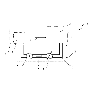
In figure 1 a first exemplary embodiment of a method for controlling deposit
60 formation in a
liquid bearing 100 system according to the present invention is illustrated.
It is provided that a
liquid 5, in particular water, inside the liquid bearing system 100 is
transported, in particular
recirculated through the liquid bearing system 100. According to the present
invention it is
provided that the liquid bearing system 100 comprises a main system 1 and a
subsystem 2.
In particular the main system 1 comprises a pipe 3 for guiding the liquid 5.
It is also thinkable
that the main system 1 also comprises other components such as a tank, a
cooling water
tower, a cooling or process system_ Moreover it is provided that the subsystem
2 is
configured as a bypass, i. e. a stream of the liquid 5 is guided in a
separated pipe 3'
bypassing the remainder of the liquid 5 that remains inside the main system 1
of the liquid
bearing system 100. As a consequence the liquid 5 inside the subsystem 2 is
mainly
equivalent to the liquid 5 inside the main system 1. For example the liquid 5
inside the
subsystem 2 has the same concentration of treatment chemicals compared to the
liquid 5
inside the main system 1. According to the present invention it is provided
that the liquid
bearing system 100 is configured such that the liquid 5 inside the subsystem 2
has a
CA 02934753 2016-06-21
WO 2015/101603 13 PCT/EP2014/079378
promoted tendency for forming deposit 60 compared with the liquid 5 inside the
main system
1. As a result the deposit 60 is formed firstly in the subsystem 2. Preferably
the subsystem 2
comprises a detection device 8 for detecting deposit 60 formation and
consequently it is
advantageously possible to detect deposit 60 inside the subsystem 2 before
deposit 60
formation starts inside the main system 1 of the liquid bearing system 100. In
other words:
The subsystem 2 according to the present invention and the detection device
for detecting
deposit formation forms a watchdog or an early warning system for the main
system 1 of the
liquid bearing system 100. In particular it is provided that the detection of
deposit 60 inside
the subsystem 2 starts a countermeasure that prevents the deposit 60 formation
inside the
main system 1 advantageously. For instance an antiscaling product is fed to
the liquid
bearing system 100 immediately in order to avoid scaling from the beginning
inside the liquid
bearing system 100. It is also conceivable that there is an extra portion of
treatment
chemicals provided for being fed to the liquid bearing system 100 as soon as a
growth of the
deposit 60 is detected in the subsystem 2. Optionally the subsystem 2
comprises a pumping
.. device 4. The pumping device 4 accelerates the liquid 5 inside the
subsystem 2 of the liquid
bearing system 100. Preferably a hydrostatic or hydrodynamic pressure from the
main 100 is
used for acceleration as well instead of the prumpmg device. Therefore the
volume flow of
the liquid 5 inside the subsystem 2 leaving the pumping device 4 has a first
velocity, wherein
in the first velocity is greater than a second velocity representing the
volume flow of the liquid
.. 5 in the main system 1. It has surprisingly found that tendency of deposit
60 formation can be
increased by increasing the volume flow or the flow velocity respectively. As
a result the
subsystem 2 according to the first exemplary embodiment is configured such
that the
tendency of forming deposit 60 inside the subsystem 2 is greater in the
subsystem2 than
inside the main system 1, wherein the thermal conditions are constant mainly.
In figure 2 a second exemplary embodiment of a method according the present
invention is
illustrated schematically. The second exemplary embodiment supplements the
first
exemplary embodiment by a heater 80 and a device for monitoring the
temperature at the
wall of the pipe 3. In particular figure 2 shows a part of the subsystem 1
including the heater
.. 80 and the device for monitoring the temperature at the wall of the pipe.
Preferably the liquid
5 inside the subsystem 2 is equal as possible to the liquid 5 inside the main
system 1 in order
to provide comparable conditions for deposit formation inside the main system
1 and the
subsystem 2. It has surprisingly found that the tendency of deposit 60
formation can be
influenced by the temperature of the liquid 5. In particular a tendency of
fouling formation is
.. increased with increasing temperature. Due to the configuration of the
subsystem 2 the
temperature inside the subsystem 2 may not be equivalent to the temperature
inside the
main system 1. In particular it is provided that a device for monitoring the
temperature
CA 02934753 2016-06-21
WO 2015/101603 14
PCT/EP2014/079378
mounted at the wall of the pipe 3,3' determinate the temperature at the wall
of the pipe 3,3'.
For this purpose a first mean 81 for measuring a first temperature 75 is
located at a first spot
being spaced by a first distance 69 from the wall of the pipe 3,3'.
Additionally a second
mean 82 for measuring a second temperature 74 is localized at a second spot
being spaced
.. by a second distance from the wall of the pipe 3,3'. Preferably the second
distance 72 is
greater than the first distance 75 and/or the first mean 81 for measuring the
first temperature
75 and the second mean 82 for measuring the second temperature 74 are included
in a
common body that has a homogenous thermal conductivity. Moreover the first
spot and the
second spot are localized between the wall of the pipe 3,3' and the heater 80.
Provided that
a temperature at the heater 78 differs from the temperature 76 at the wall of
the pipe the
temperature gradually changes from the heater 80 to the wall of the pipe 3,3'
as it is
illustrated in the plot, placed on the left side of figure 2. The plot shows
the temperature 70 in
dependency of the distance 73. Due to the linear relationship between distance
73 and
temperature 70 it is advantageously possible to approximate the temperature 76
at the wall
of the pipe based on the first temperature 75 and the second temperature 74.
Preferably the
approximation of the temperature 71 at the wall takes also into account the
first and the
second distance 69 and 72. In particular the temperature at the wall of the
pipe is
extrapolated from the first temperature 75 in the first spot and the second
temperature 74 at
the second spot. Moreover it is conceivable that the temperature profile
inside the pipe 3,3',
in particular along a direction perpendicular to the wall of the pipe, is
known and therefore the
temperature 77 at a center line 51 of the pipe 3,3' may be also approximated.
Furthermore it
is provided that a third distance 71 between the first spot and the second
spot is greater than
the thickness of the wall of the pipe 3,3.
In figure 3 a third embodiment of the method for controlling deposit 60
formation according
to the present invention is illustrated. According to the third embodiment the
subsystem 2 is
at least partially shaped as a cuboid. Preferably the heater 80 is located
symmetrical to the
center line 51 of the subsystem, i.e. a symmetry axis of the heater 80 is
located at the center
line of the subsystem 2.
In figure 4 is an exemplary device for detection deposit 60 formation is
illustrated, wherein
the device for deposit detection 8 is mounted to the pipe. Preferably the pipe
3 has a
cylindrical body and the liquid 5 is transported along a transport direction
7. Typically deposit
60 formation occurs on an inner surface of the pipes 3 of the subsystem 2.
Preferably the
device for deposit detection 8 is attached to the pipe 3. In particular the
device for detecting
deposit formation 8, in particular scaling, comprises a mean for emitting an
ultrasonic signal
and a mean for detecting a reflected ultrasonic signal. Preferably an
ultrasonic transducer
CA 02934753 2016-06-21
WO 2015/101603 15
PCVEP2014/079378
emits am emitted ultrasonic signal 20, subsequently the emitted ultrasonic
signal 20 is
transformed to a reflected ultrasonic signal 21 by reflection from a
reflection area 10 and
finally the ultrasonic signal is detected by the detection means. Preferably
the reflection area
is located opposite to the device for detecting deposit 8, in particular
scale. Based on the
5 .. travel time of the ultrasonic signal it is possible to measure an
effective diameter of the pipe
42, wherein the effective diameter of the pipe 42 is reduced compared to a
diameter of the
pipe 42 due to the deposit formation. It is also thinkable that the device for
detection deposit
formation 8 comprise a further detection mean that may identify the deposit.
Such a further
detection means may identify scale, fouling and/or corrosion. In particular it
is provided that
10 the device for detecting deposit formation 8, in particular scaling,
detects an increase in
scaling or a growth of scaling and subsequently the concentration of the
antiscaling product
inside the liquid bearing system 100 is increased immediately after the time
interval
CA 02934753 2016-06-21
WO 2015/101603 16
PCT/EP2014/079378
Reference signs
1 main system
2 subsystem/bypass
3 pipe of the main system
3 pipe of the subsystem
4 pumping device
liquid
7 transport direction in main system
7' transport direction in subsystem
8 detection device
reflection area
emitted ultrasonic signal
21 reflected ultrasonic signal
51 center line
41 diameter of pipe
42 effective diameter of the pipe
60 deposit
69 first distance
70 temperature
71 third distance
72 second distance
73 distance
74 second temperature
75 first temperature
76 temperature at the wall of the pipe
77 temperature of the liquid
78 temperature at the heater
80 heater
81 first means for measuring the first temperature
82 second means for measuring the first temperature
83 isolation
100 liquid bearing system