Note: Descriptions are shown in the official language in which they were submitted.
CA 02934838 2016-06-21
FP142125USO
1/19
Description
Title of Invention
STEEL SHEET HEATING METHOD AND STEEL SHEET HEATING
APPARATUS
Technical Field
[0001]
The present invention relates to a steel sheet heating method and a steel
sheet heating apparatus for heating a steel sheet.
Background Art
[0002]
Hot press molding, which is increasingly employed as, for example, a
method for molding a steel sheet such as the material of an automobile
component
using a high-tensile steel sheet, can mold a steel sheet in a stage of low
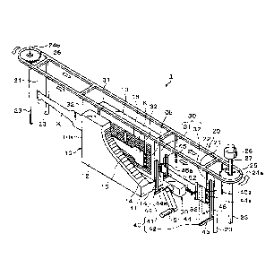
deformation
resistance by molding it at high temperature, and furthermore can provide a
component etc. with high strength and high shape accuracy by press molding
without
causing molding defects such as deformation after molding, by hardening by
quenching based on rapid cooling using the jetting of cooling water.
[0003]
In such a hot press molding method, press molding is performed such that a
steel sheet is heated at a prescribed temperature, for example 700 C to 1000
C, in a
heating furnace before press molding and then the steel sheet is conveyed to a
hot
press molding apparatus.
[0004]
As the technology of heating thus using a heating furnace, conventionally, a
mechanism in which a steel sheet is heated by heaters provided in, for
example, an
upper portion and a lower portion of the interior of a furnace while the steel
sheet is
horizontally supported by rollers and conveyed by the rollers in the furnace
has
commonly been used (Patent Literature 1).
CA 02934838 2016-06-21
FP142125USO
2/19
Citation List
Patent Literature
[0005]
Patent Literature 1: JP 2009-155691A
Summary of Invention
Technical Problem
[0006]
However, in the conventional technology mentioned above, since a steel
sheet is conveyed by rolling rollers, the steel sheet may meander in the
furnace.
Furthermore, the rollers constitute a shield, and the radiation efficiency is
poor and
rapid heating is difficult. In addition, it is necessary to roll the rollers
constantly
even at times other than conveyance in order to soak the rollers so that they
are not
thermally deformed, and the energy efficiency is poor. Moreover, due to the
thermal shock near the entrance of the furnace and the thermal stress produced
by the
unevenness of heating, there has been a concern that the roller will be
degraded or
damaged. If
the roller is damaged, the operation of the furnace stops.
Furthermore, for a surface-plated steel sheet, there have been concerns that
the
plating material will adhere to the roller in the melting temperature range
and further
the plating material adhering to the roller will adhere to the steel sheet
again.
[0007]
The present invention is made in view of these points, and an object of the
present invention is to solve the issues mentioned above by a manner in which
a steel
sheet is brought into a furnace and is heated in a state of being fixedly
supported in
the vertical direction, instead of the conventional manner in which a steel
sheet is
conveyed in a furnace while being horizontally supported by rollers.
Solution to Problem
[0008]
In order to achieve the above object, the present invention provides a steel
CA 02934838 2016-06-21
FP142125USO
3/19
sheet heating method that heats a steel sheet to be pressed before hot press
molding,
the steel sheet heating method including: bringing the steel sheet into a
heating
furnace including a heater on an inside surface of the heating furnace in a
state where
the steel sheet is supported in a vertical direction while an unnecessary
portion of the
steel sheet that becomes unnecessary after molding is fixedly supported by a
support
member; and performing heating at a prescribed temperature in the heating
furnace,
then taking the steel sheet out of the heating furnace, and after that
removing the
unnecessary portion.
The "after that" herein is not limited to the time immediately after being
taken out of the heating furnace, and may be the time of performing hot press
molding after the taking-out.
Examples of the "fixed support" in the present invention include holding the
unnecessary portion mentioned above with a clamp and hanging the unnecessary
portion by locking it with the support member. It is preferable that the steel
sheet
be fixedly supported at two or more places. This is because the steel sheet
can
thereby be prevented from bending when the steel sheet has a long-length
shape, for
example. When the steel sheet has a long length, for example when the length
in
the longitudinal direction of the steel sheet is more than 1 m, the steel
sheet is
preferably fixedly supported at both ends thereof
[0009]
According to the present invention, since a steel sheet is heated in the
heating furnace in a state of being fixedly supported in the vertical
direction by the
support member, there is no harmful effect like conventional ones occurring in
relation to the use of rollers, and the radiation efficiency is good and also
the energy
efficiency is good. Furthermore, by the fixed support in the vertical
direction by
means of the support member, the bending of the steel sheet can be suppressed.
Here, the unnecessary portion that becomes unnecessary after molding refers to
a
portion that becomes unnecessary as a product after the steel sheet is molded.
The
"fixedly supporting the unnecessary portion by means of the support member"
refers
to fixedly supporting the whole or part of the unnecessary portion by means of
the
support member.
CA 02934838 2016-06-21
FP142125USO
4/19
[0010]
In the method, the steel sheet may be moved in a vertical direction in the
heating furnace.
[0011]
Furthermore, tension may be applied to the steel sheet fixedly supported.
[0012]
According to another aspect, the present invention provides a steel sheet
heating apparatus that heats a steel sheet to be pressed before hot press
molding, the
steel sheet heating apparatus including: a heating furnace capable of
accommodating
the steel sheet in a vertical state; and a conveyance apparatus that allows
the steel
sheet to pass through a conveyance path of the heating furnace in a state of
being
supported in a vertical direction by a support member. The heating furnace
includes the conveyance path of the steel sheet formed between side walls
facing
each other and a heater that is provided on at least one surface of the side
walls and
heats the steel sheet. The conveyance apparatus includes the support member
that
fixedly supports an unnecessary portion of the steel sheet that becomes
unnecessary
after molding and a moving mechanism that moves the support member along a
rail
provided from above an upstream side of an entrance to above a downstream side
of
an exit of the heating furnace.
[0013]
In this case, a vertical drive mechanism that moves the support member in a
vertical direction may be further included.
[0014]
In addition, a shearing mechanism that shears the unnecessary portion on
the downstream side of the exit of the heating furnace may be further
included.
[0015]
Furthermore, a mechanism that applies tension to the steel sheet fixedly
supported may be further included.
Advantageous Effects of Invention
[0016]
CA 02934838 2016-06-21
FP142125USO
5/19
According to the present invention, there is no harmful effect like
conventional ones occurring in relation to the use of rollers when a steel
sheet to be
pressed is heated before hot press molding, and the radiation efficiency is
good and
also the energy efficiency is good. Furthermore, a steel sheet to be pressed
can be
heated more uniformly than in the past.
Brief Description of Drawings
[0017]
[FIG. 1] FIG. 1 is a perspective view of a steel sheet heating apparatus
according to
an embodiment.
[FIG. 2] FIG. 2 is an illustration diagram of a heating furnace in the steel
sheet
heating apparatus of FIG. 1 as viewed from the entrance side in the conveyance
direction.
[FIG. 3] FIG. 3 is a front view of a support member.
[FIG. 4] FIG. 4 is a front view of a steel sheet supported by a support body
of the
support member.
[FIG. 5] FIG. 5 is a front view of a main portion of a steel sheet showing
another
example of an extension member.
[FIG. 6] FIG. 6 is an illustration diagram schematically describing the steel
sheet
heating apparatus and a hot press molding apparatus.
Description of Embodiments
[0018]
Hereinbelow, embodiments of the present invention are described. FIG. 1
shows an overview of a steel sheet heating apparatus 1 according to an
embodiment;
a heating furnace 10 in the steel sheet heating apparatus 1 of the embodiment
includes side wall bodies 12 and 13 in a facing manner individually on both
sides of
a base 11, and the long, narrow space between the side wall bodies 12 and 13
forms a
conveyance path 14 of a steel sheet K. Heaters 15 and 15 are provided on the
inside
of the side wall bodies 12 and 13, respectively (FIG. 1 is depicted with part
of the
heating furnace 10 broken off for convenience of illustration).
CA 02934838 2016-06-21
FP142125US0
6/19
[0019]
As the heater 15, for example, an electric heater, a far-infrared heater, a
near-infrared lamp, an induction heating means, or the like may be used.
Although
in the embodiment the heater 15 is provided individually on both surfaces of
the side
wall bodies 12 and 13, the heater 15 may be provided only on one side wall
surface
depending on the type, size, shape, etc. of the steel sheet.
[0020]
A conveyance apparatus 20 of the steel sheet heating apparatus 1 according
to the embodiment includes a forward rail housing 21 provided from above the
entrance 10a side of the heating furnace 10 (the back side of the drawing) to
above
the exit 10b side of the heating furnace 10 (the front side of the drawing)
and a
backward rail housing 22 provided parallel to the forward rail housing 21.
Each of
the forward rail housing 21 and the backward rail housing 22 is supported by
support
columns 23. A support member moving path 24a and a support member moving
path 24b in a curved line form in a planar view, which serve also as a
horizontal rail,
are stretched between the ends of the forward rail housing 21 and the backward
rail
housing 22.
[0021]
The forward rail housing 21 and the backward rail housing 22 basically
have the same configuration; a detailed description thereof is given as
follows based
on the forward rail housing 21 shown in FIG. 2 and FIG. 3: the forward rail
housing
21 houses a chain conveyor 21b serving as a drive mechanism on the upper side
of
the interior of a main body unit 21a in which the lower surface side is opened
and the
cross section is shaped like a trench, and houses a rail body 21c on the lower
side.
As shown in FIG. 1, the chain conveyor 21b is stretched between a gear
sprocket 25
provided on the support member moving path 24a side and a gear sprocket 26
provided on the support member moving path 24b side, and moves cyclically
between the forward rail housing 21, the support member moving path 24a, the
backward rail housing 22, and the support member moving path 24b by the
operation
of a drive source 28 such as a motor connected to the gear sprocket 25 via a
shaft 27.
[0022]
CA 02934838 2016-06-21
FP 142125USO
7/19
A support member 30 in the embodiment is supported directly by the rail
body 21c. As shown in FIG. 3, the support member 30 includes two hanging
members 31 and 32. The hanging members 31 and 32 have the same configuration,
and thus the hanging member 31 is taken representatively for description; as
shown
in FIG. 2, the hanging member 31 is provided with a rail running member 33 and
a
cylinder 34, at a bracket 31a.
[0023]
The rail running member 33 includes an engaging unit 33a engaging with
the chain conveyor 21b and a running unit 33c provided with rollers 33b
capable of
running the rail body 21c mentioned above. The cylinder 34 is fixed to the
bracket
31a, and a rod member 34a that extends and contracts by the operation of the
cylinder 34 is suspended below the bracket 31a and has a support body 34b at
its
lower end. Therefore, the support body 34b moves vertically by the operation
of
the cylinder 34.
[0024]
As shown in FIG. 4, a plurality of protrusions 35 are provided on a lower
portion of the support body 34b in the vertical direction (in the example of
the
drawing, on four places). The steel sheet K is locked with the protrusions 35
and is
supported between the support bodies 34b and 34b of the hanging members 31 and
32. That is, extension members Ka and Kb that have no relation to the original
product, i.e. are unnecessary portions that become unnecessary after molding,
have
been formed at both ends of the steel sheet K in advance, and a locking
portion 36 to
be locked with the protrusion 35 of the support body 34b is formed in the
extension
members Ka and Kb; and by the locking portion 36 being locked with the
protrusion
35, the steel sheet K is locked with the protrusions 35 and is supported
between the
support bodies 34b and 34b of the hanging members 31 and 32.
[0025]
In the example of the embodiment, the extension members Ka and Kb are in
a T-shaped configuration, and the inside thereof is notched to form the
locking
portions 36; but instead, as shown in FIG. 5, the steel sheet K may be
supported
between the support bodies 34b and 34b of the hanging members 31 and 32 in
such a
CA 02934838 2016-06-21
FP142125USO
8/19
manner that a hole 37 is formed in the extension member Ka extending from an
end
of the steel sheet K in the horizontal direction and the protrusion 35 of the
support
body 34b is inserted into the hole 37.
[0026]
Instead of thus supporting the steel sheet K by hanging the steel sheet K
between the support bodies 34b and 34b of the hanging members 31 and 32 using
the
extension members Ka and Kb, for example, a clamping mechanism (not shown)
that
clamps the extension members Ka and Kb may be provided in the hanging members
31 and 32, and thus the extension members Ka and Kb may be clamped to fixedly
support the steel sheet K in the vertical direction.
[0027]
As shown by the broken line of FIG. 3, a tension application mechanism 39
that includes a cylinder 38 and rods 38a and 38a protruding on both sides may
be
provided between, for example, the rod members 34a and 34a of the two hanging
members 31 and 32. By putting the cylinder 38 of the tension application
mechanism 39 into operation, the rods 38a extend and contract to allow the
spacing
between the hanging members 31 and 32 to become wider; thereby, tension can be
applied to the steel sheet K supported between the support bodies 34b and 34b
of the
hanging members 31 and 32.
[0028]
Referring to FIG. 1 again for description, the steel sheet heating apparatus 1
includes, as mentioned above, the forward rail housing 21 and the backward
rail
housing 22 provided parallel to the forward rail housing 21, and the backward
rail
housing 22 has the same configuration as the forward rail housing 21.
[0029]
In the embodiment, as described above, the support member moving path
24a and the support member moving path 24b are stretched between the ends of
the
forward rail housing 21 and the backward rail housing 22, and the hanging
members
31 and 32 of the support member 30 that has been located on the backward rail
housing 22 side can be moved to the forward rail housing 21 side, that is, to
the
entrance 10a side of the heating furnace 10, via the support member moving
path 24b.
CA 02934838 2016-06-21
FP142125USO
9/19
Furthermore, the hanging members 31 and 32 of the support member 30 that has
been located on the forward rail housing 21 side, i.e. on the exit 10b side of
the
heating furnace 10, can be moved to the backward rail housing 22 side via the
support member moving path 24a. For the hanging members 31 and 32 to be
inserted into the furnace, heat-resistant steel or the like with high heat
resistance and
thermal shock properties is used; and the hanging members 31 and 32 may be
protected with a heat insulating material, which should usually be considered
as a
means for protecting the furnace equipment, and may be provided with a flow
path
inside and use a cooling means based on a cooling medium such as cooling water
or
air.
[0030]
In the embodiment, a shearing mechanism 40 that shears the extension
members Ka and Kb of the steel sheet K that has undergone the heating by the
heating furnace 10 and is located on the exit 10b side of the heating furnace
10 while
being supported by the hanging members 31 and 32 of the support member 30 is
provided on the exit 10b side of the heating furnace 10.
[0031]
The shearing mechanism 40 includes a pair of shearing apparatuses 41 and
42. The shearing apparatuses 41 and 42 have the same structure; for example, a
detailed description of the shearing apparatus 42 is given as follows: the
shearing
apparatus 42 includes a base 43 and shearing members 44 and 45 provided
perpendicular to the base 43 and facing each other. The shearing members 44
and
45 move along the base 43 by means of a drive mechanism (not shown), and can
come close to and go away from each other freely. Blades 44a and 45a are
provided
on the facing surface sides of the shearing members 44 and 45, respectively.
Therefore, by the shearing members 44 and 45 coming close together, by means
of
the blades 44a and 45a thereof, the extension members Ka and Kb of the steel
sheet
K supported between the hanging members 31 and 32 can be sheared.
[0032]
A conveyance robot 50 including an articulated arm that holds the steel
sheet K supported by the hanging members 31 and 32 of the support member 30
may
CA 02934838 2016-06-21
FP142125USO
10/19
be placed on the exit 10b side of the heating furnace 10. The conveyance robot
50
has the function of setting two clamp-type chucks 52 and 52 to ON or OFF by
the
rotational movement operation of a handle 51. The conveyance robot 50 includes
a
moving mechanism (not shown) that can move from the position on the exit 10b
side
of the heating furnace 10 freely, and can convey the held steel sheet to a hot
press
molding apparatus described later.
[0033]
The steel sheet heating apparatus 1 according to the embodiment is
configured in the above manner; next, a steel sheet heating method using the
steel
sheet heating apparatus 1 is described.
[0034]
First, the steel sheet K to be molded by hot press molding is supported at the
hanging members 31 and 32 of the support member 30 located on the forward rail
housing 21 side, on the entrance 10a side of the heating furnace 10. Then,
tension
is applied to the supported steel sheet in the horizontal direction by the
tension
application mechanism 39 shown in FIG. 3.
[0035]
In this state, the drive mechanism of the forward rail housing 21 is put into
operation to drive the chain conveyor 21b, and thereby the hanging members 31
and
32 of the support member 30 supporting the steel sheet K are moved to the
heating
furnace 10; and the steel sheet K is heated to a prescribed temperature, for
example
700 C to 1000 C, by the heaters 15 in the heating furnace 10. At this time,
the
cylinders 34 of the hanging members 31 and 32 may be put into operation to
extend
and contract the rod members 34a, and thus the steel sheet K supported at the
hanging members 31 and 32 can be moved in the vertical direction.
[0036]
After the steel sheet K is heated to the prescribed temperature, the chain
conveyor 21b of the forward rail housing 21 is driven, and thus the hanging
members
31 and 32 of the support member 30 supporting the steel sheet K are taken out
of the
heating furnace 10 and are moved to the space on the exit 10b side of the
heating
furnace 10. The steel sheet K may be heated in the heating furnace 10 while
being
CA 02934838 2016-06-21
FP142125USO
11/19
conveyed constantly, or may be heated in a state of being stationary in the
heating
furnace 10.
[0037]
After the hanging members 31 and 32 of the support member 30 supporting
the steel sheet K have stopped in a prescribed position in the space on the
exit 10b
side of the heating furnace 10, the conveyance robot 50 is brought close to
the steel
sheet K, and the steel sheet K is held by the chucks 52 and 52. After that,
the
tension applied to the steel sheet K the tension application mechanism 39 is
released;
and the shearing apparatuses 41 and 42 are put into operation, and the
extension
members Ka and Kb of the steel sheet K supported between the hanging members
31
and 32 are sheared by the shearing members 44 and 45. Thus, the conveyance
robot
50 enters a state of supporting the steel sheet K from which the extension
members
Ka and Kb, which are unnecessary portions after molding, have been removed.
[0038]
After that, as shown in FIG. 6, while the steel sheet K is held by the chucks
52 and 52, the steel sheet K is conveyed by an articulated arm 53 of the
conveyance
robot 50 to a lower mold 63 of a molding and rapid cooling stage 62 of a hot
press
molding apparatus 60, which stage performs press molding and rapid cooling
treatment. Then, after the steel sheet K is set in a prescribed position,
prescribed
press molding by the pressing of an upper mold 64 and rapid cooling treatment
are
performed on the steel sheet K, and the steel sheet K is processed into a
prescribed
product.
[0039]
Thus, by the embodiment of the present invention, the steel sheet K is
brought into and heated by the heating furnace 10 including the heaters 15 on
the
surfaces of the side wall bodies 12 and 13 in a state where the steel sheet K
is fixedly
supported in the vertical direction via the extension members Ka and Kb, which
are
unnecessary portions that become unnecessary after press molding, by the
hanging
members 31 and 32 of the support member 30; therefore, as compared with a
conventional system in which a steel sheet is heated while being supported in
a
horizontal state by rollers, firstly, the steel sheet K can be heated more
uniformly
CA 02934838 2016-06-21
FP142125USO
12/19
than in the past without the steel sheet K meandering. Furthermore, since
there is
no shield between the heater 15 and the steel sheet K, the heat from the
heater 15 can
be given to the steel sheet K with good efficiency, and the radiation
efficiency is
good and more rapid heating than in the past is possible. In addition, since
at times
other than heating there is no need to put the support member 30 in movement,
the
energy efficiency is better than in the past. In addition, since rollers are
not used,
there is no possibility of shutdown due to damage to rollers.
[0040]
Furthermore, in the embodiment described above, since the support body
34b supporting the steel sheet K can be moved vertically by putting the
cylinder 34
of the support member 30 into operation, the heating unevenness can be
suppressed
by putting the cylinder 34 into operation to move the steel sheet K in the
vertical
direction while the steel sheet K is located in the heating furnace 10, and
thereby
more uniform heating can be made. Therefore, also heating unevenness in the
vertical direction due to the arrangement of heaters 15 and the variation in
heating
output characteristics can be prevented.
[0041]
Furthermore, in the embodiment described above, since the steel sheet K to
be heated is fixedly supported in the vertical direction via the extension
members Ka
and Kb by the hanging members 31 and 32 of the support member 30 and, in
particular, is fixedly supported at two places of both ends, the steel sheet K
does not
bend even when the steel sheet K has a shape long in the horizontal direction.
Furthermore, since tension is applied to the steel sheet K to be heated in the
horizontal direction by the tension application mechanism 39, the deformation
due to
the reduction in rigidity and the thermal expansion of the steel sheet K
during heating
can be suppressed.
[0042]
Furthermore, since the extension members Ka and Kb of the steel sheet K
used when the steel sheet K is fixedly supported in the vertical direction are
unnecessary portions that become unnecessary after press molding, the steel
sheet K
itself can be heated uniformly in whole. Moreover, in the case where the steel
sheet
CA 02934838 2016-06-21
FP142125USO
13/19
K is a plated steel sheet, even when it is heated in the melting temperature
range,
there is no concern that the molten plating material will adhere to the steel
sheet K
again.
[0043]
In the embodiment described above, since the extension members Ka and
Kb are, immediately after heating, sheared and removed in the steel sheet
heating
apparatus 1 by the shearing mechanism 40 installed in the steel sheet heating
apparatus 1, the extension members Ka and Kb, which are unnecessary portions,
can
be removed in a state of high temperature and low strength, and there is no
influence
on the shape, quality, and performance of the product after molding. The
extension
members Ka and Kb left on the hanging members 31 and 32 of the support member
30 after shearing may be collected to a collection box or the like via a chute
(not
shown) or the like. In the case where the press mold can be provided with a
shearing mechanism, the extension members Ka and Kb may be sheared and
removed simultaneously with the pressing in the hot press molding apparatus
60.
[0044]
The hanging members 31 and 32 of the support member 30 after the steel
sheet K is conveyed by the conveyance robot 50 in the above way may be moved
to
the backward rail housing 22 side through the support member moving path 24a
and
then moved to the entrance 10a side of the heating furnace 10 through the
support
member moving path 24b, and the steel sheet K to be processed next may be set
at
the hanging members 31 and 32 of the support member 30 again in a prescribed
position on the entrance 10a side of the heating furnace 10.
[0045]
As is clear from FIG. 1, the steel sheet heating apparatus 1 uses the heating
furnace 10 that heats the steel sheet K in a vertical state from both sides,
and the
forward rail housing 21 and the backward rail housing 22 of the conveyance
apparatus 20 are installed above the heating furnace 10; therefore, the
occupied floor
area is much smaller than that of a conventional horizontal support-type
heating
furnace, and thus a large number of steel sheet heating apparatuses 1 can be
juxtaposed. Therefore, productivity is very good in operation with the same
floor
CA 02934838 2016-06-21
FP142125USO
14/19
area.
[0046]
Furthermore, in the embodiment described above, the movement of the
hanging members 31 and 32 of the support member 30 is based on the chain
conveyor 21b installed in the forward rail housing 21 and the backward rail
housing
22, and an arrangement in which the drive mechanism is installed outside the
heating
furnace 10 and the forward rail housing 21 does not receive radiant heat
directly
from the opening of the heating furnace as shown in FIG. 2 is possible; thus,
the
thermal effect from the heating furnace 10 on the drive system can be
suppressed to a
minimum. When a thermal shield is provided as appropriate, the support member
30 itself may be equipped with a self-propelled drive mechanism, as a matter
of
course.
[0047]
The preferred embodiment(s) of the present disclosure has/have been
described above with reference to the accompanying drawings, whilst the
present
disclosure is not limited to the above examples. A person skilled in the art
may find
various alterations and modifications within the scope of the appended claims,
and it
should be understood that they will naturally come under the technical scope
of the
present disclosure.
Industrial Applicability
[0048]
The present invention is useful for the heating of a steel sheet before the
steel sheet is molded by hot press molding.
Reference Signs List
[0049]
1 steel sheet heating apparatus
10 heating furnace
10a entrance
10b exit
CA 02934838 2016-06-21
FP142125US0
15/19
11 base
12, 13 side wall body
14 conveyance path
15 heater
20 conveyance apparatus
21 forward rail housing
21a main body unit
21b chain conveyor
21c rail body
22 backward rail housing
23 support column
24a, 24b support member moving path
25, 26 gear sprocket
27 shaft
28 drive source
30 support member
31, 32 hanging member
31a bracket
33 rail running member
33a engaging unit
33b roller
33c running unit
34 cylinder
34a rod member
34b support body
protrusion
36 locking portion
37 hole
38 cylinder
30 38a rod
39 tension application mechanism
CA 02934838 2016-06-21
FP142125USO
16/19
40 shearing mechanism
41, 42 shearing apparatus
43 base
44, 45 shearing member
44a, 45a blade
50 conveyance robot
51 handle
52 chuck
53 articulated arm
60 hot press molding apparatus
62 molding and rapid cooling stage
63 lower mold
64 upper mold
K steel sheet
Ka, Kb extension member