Note: Descriptions are shown in the official language in which they were submitted.
SYSTEM AND PROCESS FOR ESTIMATING SOLVENT RECOVERY
CROSS-REFERENCE TO RELATED APPLICATIONS
[0001]
This application claims all benefit, including priority, to U.S. Provisional
Patent
Application 62/188,022, filed July 2, 2015, and entitled "SYSTEM AND PROCESS
FOR
ESTIMATING SOLVENT RECOVERY."
FIELD
[0002] The improvements generally relate to the field of solvent recovery from
an
emulsion stream and in particular to estimating solvent recovery concentration
from an
emulsion stream in a hydrocarbon recovery process.
BACKGROUND
[0003] The high viscosity of heavy oil and bitumen make well production and
pipe
transportation difficult. A hydrocarbon recovery process may involve
introducing production
initiating fluid (e.g. water, steam, gas, solvent) to stimulate the reservoir
and effect
recovery of a produced fluid. This process may reduce the viscosity of the
heavy oil and
bitumen. The produced fluid can then be pumped back to the surface or
otherwise
recovered from the well.
SUMMARY
[0004] In accordance with one aspect, there is provided a system for
estimating solvent
recovery. The system includes a density meter for obtaining density data for
produced fluid
flowing from a reservoir; a temperature sensor for measuring the temperature
of the
produced fluid; a water cut meter for measuring a water content of the
produced fluid; and
a controller. The controller is configured to: obtain measurement data from
the density
meter, temperature sensor and water cut meter, the measurement data including
data for a
pre-solvent injection period and data for a post-solvent injection period;
generate a two-
component produced fluid density model for the pre-solvent injection period
and the post-
solvent injection period based on the measurement data for the pre-solvent
injection
- 1 -
Date Recue/Date Received 2022-08-11
period; and using a three-component produced fluid density model, determine
recovered
solvent over the post-solvent injection period based on a difference between
the two-
component produced fluid density model and the density data for the post-
solvent injection
period.
[0005] In accordance with another aspect, there is provided a method for
estimating
solvent recovery. The method includes: obtaining, from a density meter,
density data for
produced fluid flowing from a reservoir during a pre-solvent injection period
and a post-
solvent injection period; receiving, from a temperature sensor, temperature
data of the
produced fluid during the pre-solvent injection period and the post-solvent
injection period;
receiving, from a water cut meter, water content data for the produced fluid
during the pre-
solvent injection period and the post-solvent injection period; generating a
two-component
produced fluid density model for the pre-solvent injection period and the post-
solvent
injection period based on the measurement data for the pre-solvent injection
period; and
using a three-component produced fluid density model, determining recovered
solvent
over the post-solvent injection period based on a difference between the two-
component
produced fluid density model and the density data for the post-solvent
injection period.
[0006] In accordance with another aspect, there is provided a non-transitory,
computer-
readable medium or media having stored thereon computer-readable instructions.
The
instructions which when executed by at least one processor, configure the at
least one
processor for: obtaining, from a density meter, density data for produced
fluid flowing from
a reservoir during a pre-solvent injection period and a post-solvent injection
period;
receiving, from a temperature sensor, temperature data of the produced fluid
during the
pre-solvent injection period and the post-solvent injection period; receiving,
from a water
cut meter, water content data for the produced fluid during the pre-solvent
injection period
and the post-solvent injection period; generating a two-component produced
fluid density
model for the pre-solvent injection period and the post-solvent injection
period based on
the measurement data for the pre-solvent injection period; and using a three-
component
produced fluid density model, determining recovered solvent over the post-
solvent injection
- 2 -
Date Recue/Date Received 2022-08-11
period based on a difference between the two-component produced fluid density
model
and the density data for the post-solvent injection period.
[0007] Many further features and combinations thereof concerning embodiments
described herein will appear to those skilled in the art following a reading
of the instant
disclosure.
DESCRIPTION OF THE FIGURES
[0008] In the figures,
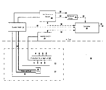
[0009] Figure 1 shows an example system for estimation of solvent recovery
using a
Coriolis Meter in a production line.
[0010] Figure 2 shows an example process for estimation of solvent recovery.
[0011] Figures 3 and 4 show flowcharts showing aspects of example systems.
[0012] Figure 5 illustrates a graph showing an example plot of data from a
Coriolis
meter.
[0013] Figures 6, 7 and 8 illustrate example calculations and measured
data.
[0014] Figure 9 shows an example graph illustrating history matched density
curves.
[0015] Figure 10 shows an example computing script.
[0016] Figure 11 shows an example graph illustrating history matched
density curves.
[0017] Figure 12 shows an example graph for solvent recovery in the liquid
phase.
[0018] Figure 13 shows another graph of estimate solvent recovery.
[0019] Figure 14 is a schematic diagram of the controller.
- 3 -
Date Recue/Date Received 2022-08-11
DETAILED DESCRIPTION
[0020] Figure 1 shows an example system 10 for estimation of solvent recovery
concentration from a hydrocarbon recovery process. The system in Figure 1
shows an
example steam-assisted gravity drainage (SAGD) system; however, in other
embodiments,
other systems involving one or other different hydrocarbon recovery processes
may be
utilized. For example, other systems in which solvent may be applied include
but are not
limited to cyclic stream stimulation systems, steam drive systems, steam
solvent hybrids,
diluent in bitumen and heavy oil transportation pipelines and the like.
[0021] In an aspect, embodiments described herein provide systems, processes
and
devices for estimating the fraction of injected solvent that is recovered
within the produced
fluid of a hydrocarbon recovery process. The processes and devices may use
Coriolis
meter density computations and history match techniques.
[0022] An example hydrocarbon recovery process is Expanding Solvent Steam-
Assisted Gravity Drainage (ES-SAGD). ES-SAGD generally involves an injection
system
16 injecting production initiating fluid 18 into a reservoir to stimulate the
reservoir and
effect recovery of a produced fluid 24. The production initiating fluid 18 can
include
condensed steam (water), or condensed steam and solvent. The produced fluid
can
include hydrocarbon material and water; and after solvent has been injected
with the
production initiating fluid, the produced fluid can additionally include
solvent. In some
instances, the produced fluid can be an emulsion.
[0023] "Hydrocarbon" is an organic compound consisting primarily of hydrogen
and
carbon, and, in some instances, may also contain heteroatoms such as sulfur,
nitrogen
and oxygen. "Hydrocarbon material" is material that consists of one or more
hydrocarbons.
For example, in some instances, the hydrocarbon material can include bitumen.
[0024] In this context, the term "solvent" is intended to refer to material
that, when
disposed in the liquid state, is able to, at least to some extent, dissolve in
bitumen or
reduce the viscosity of the bitumen (hydrocarbon material). In some examples,
solvent
may include or comprise diluent.
- 4 -
Date Recue/Date Received 2022-08-11
[0025] The produced fluid is conducted through a production line 12.
[0026] In some embodiments, the recovery estimation process determines
fraction or
percentage of solvent within the produced fluid. For example, as described
herein, based
on density information obtained from density meter data and water cut data for
the
produced fluid, the fraction of solvent within the produced fluid can be
estimated. In some
examples, this fraction can be used to determine an absolute amount of solvent
in the
produced fluid, a ratio of an amount of solvent in the produced fluid relative
to an amount
of injected solvent, a rate of solvent recover, or a combination thereof.
Other related
calculations may also be possible.
[0027] In some examples, these recovered solvent estimations may be used to
assess
efficiency, environment conditions, economic feasibility, appropriate
processing, regulatory
compliance, and so on, of the process.
[0028] For example, solvent injected into a well or reservoir may be an
expensive
aspect of the process and in some cases may be more expensive than the
hydrocarbon
being extracted. Accordingly, a system including a process for estimating an
amount, rate
or percentage of solvent recovery can, in some instances, be important to
determine
whether adjustments to the solvent injection process (amount, rate, timing,
etc.) are
required, the economic viability of a well, etc.
[0029] In some examples, a system including a process for estimating solvent
recovery
may reduce or eliminate the cost, equipment or time required to perform
detailed emulsion
sampling / lab analysis and may provide a means of continuous monitoring of
returning
solvent not possible using emulsion sampling methods.
[0030] With reference to Figure 1, in an example multi-well system, during the
production phase, an injection well 20 functions to inject a production-
initiating fluid into the
reservoir to effect mobilization of the hydrocarbon material within the
reservoir such that
the hydrocarbon material is conducted to the well for production through a
production well
22. In some embodiments, for example, the production-initiating fluid includes
steam.
- 5 -
Date Recue/Date Received 2022-08-11
[0031] The production phase of the process occurs after interwell
communication has
been established within the interwell region between the injection and
production wells 20,
22. The interwell communication is established when the injected production-
initiating fluid
18 is able to communicate heat to hydrocarbon material within the reservoir
such that the
hydrocarbon material is mobilized, and the mobilized hydrocarbon material is
able to be
conducted, e.g. by gravity, through the interwell region to the production
well 22.
[0032] In
some embodiments, for example, initially, the reservoir has relatively low
fluid
mobility. In order to enable the injected production-initiating fluid (being
injected through
the injection well) to promote the conduction of the reservoir hydrocarbons,
within the
reservoir, to the production well, heat and mass transfer communication must
be
established between the wells through the interwell region. This communication
may be
established during a "start-up" phase. During the start-up phase, the
interwell region is
heated. In some embodiments, for example, the heat is supplied to the
interwell region by
circulating a start-up phase fluid (such as steam, or a fluid including steam)
through one or
both of the wells. The heat that is supplied to the interwell region heats the
reservoir
hydrocarbons within the interwell region, thereby reducing the viscosity of
the reservoir
hydrocarbons. Eventually, the interwell region becomes heated to a temperature
such that
the hydrocarbon material is sufficiently mobile (i.e. the hydrocarbon material
has been
"mobilized") for displacement to the production well 22 by at least gravity
drainage.
Eventually, sufficient hydrocarbon material drains such that space previously
occupied by
the hydrocarbon material effects fluid communication between the injection
well 20 and the
production well 22, and this space defines a first communication zone. The
development
of the first communication zone signals completion of the start-up phase and
conversion to
a production phase.
[0033] During the production phase, the first communication zone effects fluid
communication between the production-initiating fluid 18, being injected
through the
injection well 20, with hydrocarbon material within the reservoir, such that
the injected
production-initiating fluid 18 is conducted through the first communication
zone and
becomes disposed in heat transfer communication with hydrocarbon material
within the
- 6 -
Date Recue/Date Received 2022-08-11
reservoir such that the hydrocarbon material becomes heated. When sufficiently
heated
such that its viscosity becomes sufficiently reduced, the hydrocarbon material
becomes
mobilized, and, in this respect, the hydrocarbon material is able to be
conducted, by at
least gravity drainage, through the first communication zone, to the
production well 22.
During the production phase, while the production-initiating fluid 18 is being
injected into
the first communication zone via the injection well 20, as the mobilized
hydrocarbon
material drains to the production well 22, space previously occupied by the
hydrocarbon
material within the reservoir becomes occupied by the injected production-
initiating fluid
18, thereby exposing a fresh hydrocarbon material surface for receiving heat
from the
production-initiating fluid 18 (typically, by convection within the first
communication zone
created). This repeated cycle of heating, mobilization, drainage, and
establishment of heat
transfer communication between the production-initiating fluid 18 and a
freshly exposed
hydrocarbon material source results in the growth of the first communication
zone, with the
freshly exposed hydrocarbon material being disposed along an edge of the
communication
zone. In some embodiments, for example, the first communication zone includes
a
"vapour chamber". In some embodiments, for example, the vapour chamber may
also be
referred to as a "steam chamber". In some embodiments, for example, the growth
of the
first communication zone is upwardly, laterally, or both.
[0034] After the intenNell communication has been established between the
wells,
production of hydrocarbon material from the reservoir may be effected during
the
production phase, as described above. In this way, a hydrocarbon recovery
process, such
as a thermally-actuated gravity drainage-based process, is implemented via the
well pairs.
In some embodiments, for example, where the production-initiating fluid 18
includes
steam, the process that is effecting this production is described as "steam-
assisted gravity
drainage" or "SAGD". In some embodiments, for example, the first communication
zone
includes a vapour chamber, such as, for example, a "steam chamber".
[0035] In other example embodiments there may be multiple pairs of wells. In
other
example embodiments there may be different well configurations. The example
shown in
Figure 1 is for illustrative purposes.
- 7 -
Date Recue/Date Received 2022-08-11
[0036] In other example embodiments, a single well may be an injection well 20
and a
production well 22 such as in a cyclic stream stimulation system.
[0037] An injection system 16 injects the production initiating fluid 18
into or proximate
an injection well 20 of the reservoir to stimulate the reservoir and effect
recovery of the
produced fluid. This may reduce the viscosity of the heavy oil and bitumen,
causing the
heavy oil to drain or otherwise flow into a production well 22 of the
reservoir and pump out
using a pump 26. During a pre-solvent injection period, the production
initiating fluid can
include only steam (water). At a subsequent period of time (i.e. during a
solvent-injection
period), the production initiating fluid can include solvent and steam.
[0038] In some examples, one or more controllers 34 can control the amount of
steam
and/or solvent which is in the production initiating fluid. The controller(s)
34 may store or
otherwise obtain data indicated the amount of solvent injected over time.
[0039] Produced fluid is conducted from the reservoir through a production
line. The
production line 12 includes or otherwise conducts the produced fluid to a
device such as a
density meter to measure data for obtaining density data representing the
density of the
produced fluid flowing from the reservoir.
[0040] For example, as illustrated in Fig. 1, the density meter can be a
Coriolis meter.
The Coriolis meter, in some embodiments, can be configured to measure the mass
flow
rate of the produced fluid being conducted through the produced line. In some
embodiments, the Coriolis meter may be configured to measure the density of
the
produced fluid directly.
[0041] In some embodiments, the controller 34 can be configured to obtain the
density
information for the fluid being conducted through the produced line from the
density meter.
In some embodiments, the controller 34 can receive the density information
directly from
the density meter.
[0042] In another embodiment, the controller 34 can obtain the density
information
based on a calculation with the mass flow rate data. For example, density
information may
- 8 -
Date Recue/Date Received 2022-08-11
be obtained by dividing the mass flow rate with the volumetric flow rate of
the produced
fluid being conducted through the production line. In some embodiments, the
controller 34
can obtain volumetric flow rate data from a flow meter on or attached to the
production
line. In some examples, a Coriolis meter may provide volumetric flow rate
data.
[0043] In some embodiments, the controller 34 can have interfaces 40, 42 with
the test
separator system 28 and/or the injection system 16. In some embodiments, the
controller
34 is configured to send and/or receive data and/or instructions to/from the
test separator
system 28 and/or the injection system 16 via these interface(s).
[0044] In some embodiments, the system can include a water cut meter 46 (e.g.
Agar
meter) or other device to measure the proportion of water in the produced
fluid flowing
through the production line 12.
[0045] In some embodiments, the controller 34 can have interfaces 44, 44 for
receiving
data from the Coriolis Meter 14 and/or the water cut meter 46.
[0046] The proportion of water may be referred to as the water cut or On-Line
Water
Determination. In some embodiments, the water cut meter can be an individual
device 46
as illustrated in the example system of Fig. 1. For example, the water cut
meter may be a
SchlumbergerTM Vx multiphase meter. Alternatively, or additionally, a test
separator
system 28 may also have a water cut meter to measure water cut data. The water
cut data
may be expressed as a percentage amount of water in the produced fluid being
analyzed.
The water cut data may be weight/mass based or volume based.
[0047] The water cut meter 46 computes and outputs water measurement data 48
to the
controller 34.
[0048] In some embodiments, the system may optionally include a test separator
system 28 to measure produced liquid and vapor flows. At least a portion of
the produced
fluid from the reservoir may be directed to the test separator system 28 for
testing. The test
separator system 28 may use a phase separation technique, for example, to
separate
components 30, 32 of the produced fluid. Test separator system 28 may also
include a
- 9 -
Date Recue/Date Received 2022-08-11
water cut meter for computing water content measurements at the outlet of the
test vessel.
In some examples, the water cut measurements can be corrected for water vapour
and
solvent vapour losses from the test separator system to obtain a more accurate
water cut
estimate for the fluid in the emulsion line 12.
[0049] The controller 34 may receive additional data from lab analysis output
or the test
separator, such as, for example, the density ranges of water, bitumen and
solvent
separated from produced fluid. In some examples, the meter(s)/device(s) for
measuring/obtaining the data are positioned along an output path before any
test
separator in the system as some solvent may escape as vapour in the separator
and may
provide less accurate information regarding the emulsion/material flowing from
the
reservoir.
[0050] In some examples, the system 10 can include a temperature sensor for
measuring the temperature of the fluid flowing from the reservoir. In some
examples, a
Coriolis meter 14 may also be or include a temperature sensor.
[0051] As described herein, with the measured data during a pre-solvent
injection
period, the controller can be configured to determine a density of the
hydrocarbon material.
Based on the density of the hydrocarbon material and two separate computer
models for
produced fluid, the controller 14 can estimate solvent recovery.
[0052] The controller 14 includes at least one data storage device and at
least one
processor configured to receive measured data from the system for a pre-
solvent injection
period to generate a two-component produced fluid density model (e.g. a model
wherein
the produced fluid has two components: water and hydrocarbon material). This
model may
be based on a determination of the density of the hydrocarbon material in the
produced
fluid during the pre-solvent injection period using laboratory test data
expressed under
standard conditions (15 degrees C and 101.3 KPa).
[0053]
After injection of solvent in the production initiating fluid 18 has started,
returning
produced fluid 24 may tend to create a lower density reading than that
calculated by the
- 10 -
Date Recue/Date Received 2022-08-11
two component model. The system can be configured to estimate the recovered
solvent
based on this difference.
[0054] As described in the example embodiments below, after the introduction
of solvent
in the production initiating fluid 18, the controller 34 can be configured to
receive measured
data from the system for a post-solvent injection period to determine the
fraction of the
produced fluid which is solvent by applying a three-component produced fluid
density
model (e.g. a model wherein the produced fluid has three components: water,
hydrocarbon
material and solvent).
[0055] Data received by the controller 34 and/or one or more processors of the
system
can be used to estimate solvent recovery as illustrated for example, by the
example
process illustrated in Figure 2.
[0056] Figure 2 shows an example process 100 for estimation of solvent
recovery. In
some embodiments, the process involves the output data 44 from the density
device (e.g.
Coriolis meter), temperature sensor, and water cut meter at the produced fluid
line 12.
[0057] At 102, the controller can be configured to obtain density data for the
produced
fluid flowing from the reservoir during a period before solvent is injected
(the pre-solvent
injection period) and during any period for which solvent is and/or has
previously been
injected (the post-solvent injection period). In some examples, the density
data can include
the mass flow rate, and volumetric flow rate for determining the density of
the material (e.g.
produced fluid) being conducted through the produced fluid or other outgoing
line. In some
examples, the density data include the density of the produced fluid.
[0058] In some embodiments, the density data can be received from separate
devices
such as a density meter and a separate flow meter. In other embodiments, the
density
data can be received by a single device, such as a Coriolis meter.
[0059] In some embodiments, the density data can be measured directly by the
meter(s)/device(s). In some embodiments, some of the density data can be
obtained or
otherwise derived from measured data. For example, a density may be calculated
from a
- 11 -
Date Recue/Date Received 2022-08-11
mass flow rate and a volumetric flow rate. These calculation(s) may be
performed by the
density meter (e.g. Coriolis meter), the controller or another device.
[0060] At 104, the controller can be configured to receive temperature data
from a
temperature sensor. The temperature data can indicate the temperature of the
produced
fluid being conducted from the reservoir. In some examples, the temperature
sensor may
be its own sensor or it may part of another device such as a Coriolis meter.
[0061] At 106, the controller can be configured to receive water cut data from
a water
cut meter. The water cut data can indicate the water content of the material
flowing from
the reservoir. For example, the water cut data can indicate the percentage or
fraction of
water in the material from the reservoir. The water cut data can in some
examples be
mass-based or volume-based.
[0062] The controller can be configured to receive and/or obtain any or all of
the data
from the device(s)/meter(s) on a periodic or continual basis.
[0063] At 108, a two-component produced-fluid density model can be generated
based
on the measurement data from the density meter, the temperature sensor and the
water
cut density meter during the pre-solvent injection period. The two-component
produced
density model can define an estimated density for the produced fluid flowing
through the
production line. In some embodiments, the two-component produced fluid density
model
can be based on the fraction of the material which is water, and the fraction
of the material
which is a hydrocarbon material and their respective densities. In some
examples, through
the two-component produced fluid density model, it may be assumed that all
material in
the produced fluid line other than water is a hydrocarbon material or is
otherwise treated
as a single component of the produced fluid.
[0064] In some embodiments, generating the two-component model can include
calculating hydrocarbon material and water densities at standard conditions
using
laboratory analyses. Information from the temperature sensor may be used to
correct the
densities of the two components to process temperatures, and water cut
estimates from
the test separator meter or in-line water cut meter can be used to create the
two
- 12 -
Date Recue/Date Received 2022-08-11
component density model curve which is history matched to the data from the
density
meter during the pre-solvent injection period.
[0065] In some embodiments, the two-component produced fluid density model can
be
based on:
Produced fluid density = (Water density)(water cut) + (hydrocarbon material
density)(1 ¨
water cut)
[0066] In the two-component model, in some examples, the density of the
produced fluid
in the production line at a snapshot or period of time can be modelled based
on a
measured water density, a water cut and an estimated density of the
hydrocarbon material.
[0067] Generating a material density model can include computing the produced
fluid
density based on measurements of the water cut, and a value of the hydrocarbon
material
density and the water density. In some examples, the water density and
hydrocarbon
density can be initially based on data received and/or determined based on an
analysis of
recovered samples or otherwise.
[0068] In some examples, generating the two-component produced fluid density
model
and/or obtaining measurement data can include interpolating and/or time
matching
measured density data, temperature data and/or water cut data to provide a
complete data
set or a set of data otherwise suitable for analysis over the measured time
frames.
[0069] In some embodiments, generating the two-component produced fluid
density
model can include history matching the two-component produced fluid density
model with
the pre-solvent injection measured density data with the pre-solvent injection
hydrocarbon
material density as a matching parameter.
[0070] In some examples, the history matching can use the density value for
the
hydrocarbon density from the sample analysis as an initial value for the
history matching
process. In some examples, the history matching or other algorithm used to
generate the
- 13 -
Date Recue/Date Received 2022-08-11
two-component model may determine or estimate the pre-solvent injection
hydrocarbon
material density.
[0071] In some embodiments, the history matching process compares the two
component density model density time series output expressed at process
conditions to
the measured density values obtained from the in-line density meter. The
inputs to the two
component model calculations include measured process temperatures and
pressures at
the density meter, water cuts from the test separator or in-line water cut
meter and
laboratory data on densities at standard conditions for both the produced
water and the
produced hydrocarbon material. A density estimate for the production line
contents is
derived from a two component model using the water cut estimates and process
conditions
to arrive at process condition densities. The estimated hydrocarbon material
density at
standard conditions is used as a history matching parameter such that the sum
of the
absolute errors between the two component model and the measured densities are
minimized over a period prior to the onset of solvent injection. The
adjustment of the
history matching parameter can either be done manually or a goal seeking
algorithm can
be used to obtain the optimum hydrocarbon material density.
[0072] With this value of the hydrocarbon material density, the produced fluid
density
can be fully-defined (e.g. by the above-equation) using known and measured
values for
different periods or instances of time.
[0073] In
some instances, the estimated hydrocarbon material density is representative
of the density of the hydrocarbon material fraction of the produced fluid.
[0074] In some embodiments, the two-component model is further refined based
on the
temperature or pressure of the material flowing from the reservoir. For
example, the
density of the hydrocarbon material and/or the water can be adjusted based on
the
tern perature.
[0075] In some examples, the density of the hydrocarbon material and/or the
water can
be adjusted based on the pressure. In some examples, it may be assumed that
variations
in pressure have little or no effect on liquids and the relatively dense
produced material. In
- 14 -
Date Recue/Date Received 2022-08-11
some examples, by eliminating pressure from the equation, the system may be
simplified
by eliminating measuring device requirements and/or by reducing the complexity
and
computation require to generate the models.
[0076] In some embodiments, the two-component model including temperature can
be
based on:
produced fluid density = (Water density @ process temperature)(water cut) +
(hydrocarbon
material density at process conditions)(1 ¨water cut).
[0077] The water density can be adjusted based on the measured (process)
temperature:
S.G
water @ process cond =
water std. Cond
(0.001+0.000001436*(-4.8872+0.134186*Tprocess + 0.00212868*(Tpr )2))
[0078] The hydrocarbon material density can be adjusted based on the measured
(process) temperature:
X = 141.5* 1000/ (131.5*S.G bitumen std. Cod )/(1047+T
.. -20)
bitumen @ process cond process
[0079] In some embodiments, the equations above can be used to adjust density
at
standard conditions to other conditions.
[0080] At 110, the recovered solvent over the post-solvent injection period
can be
determined using a three-component produced fluid density model. The three-
component
produced fluid density model can define an estimated density for the material
flowing
through the production line. In some embodiments, the three-component produced
fluid
density model can be based on the fraction of the material which is water, the
fraction of
the material which is a hydrocarbon material, and the fraction of the material
which solvent.
- 15 -
Date Recue/Date Received 2022-08-11
[0081] In some embodiments, the three-component produced fluid density model
can be
based at least on the water content of the produced fluid, the water density,
the
hydrocarbon material density, the solvent density, the solvent content of the
produced fluid
and the temperature.
[0082] In some examples, with the hydrocarbon material density from the two-
component model and the measured data for the post-solvent injection period,
the
recovered solvent over the post-solvent injection period can be determined.
[0083] In some examples, the recovered solvent can be determined over the post-
solvent injection period based on a difference between the two-component
produced fluid
density model and the density data for the post-solvent injection period. This
difference in
material densities may be assumed to be caused by the solvent.
[0084] In some embodiments, the three-component produced fluid density model
can be
based on:
Produced fluid density = (water density)(water cut) + (hydrocarbon material
density)(1 ¨ water cut - solvent cut) + (solvent density)(solvent cut).
[0085] In some embodiments, the water density and/or the hydrocarbon material
density
can be adjusted based on the measured (process) temperature as described above
or
otherwise.
[0086] Similarly, in some embodiments, adjusting the solvent density can be
based on
the measured (process) temperature using the same formula as for the
hydrocarbon
density adjustment.
[0087] Thus:
Produced fluid density = (water density @ process temp.)(water cut) +
(hydrocarbon material density @ process conditions)(1 ¨ water cut - solvent
cut)
+ (solvent density @ process conditions)( solvent cut).
- 16 -
Date Recue/Date Received 2022-08-11
[0088] Solving for the solvent cut, in some examples, the recovered solvent
can be
calculated/estimated using the emulsion flow rate.
[0089] In some embodiments, the controller can be configured to determine 114
the
percentage or rate of recovered solvent by comparing the estimated recovered
solvent
with data indicating the times, rates, amounts that solvent is injected in the
reservoir.
[0090] At 116, the controller 34 or operator can generate feed-back or feed-
forward
control signals to control or communicate operating parameters of the system.
For
example, the controller 34 may transmit feedback control signals to the
injection system 16
to stop or start injection of solvent or steam/water, and/or adjust the amount
of solvent or
steam/water injected. As another example, the controller 34 may transmit
feedback control
signals to the test separator system to control water cut measurement
parameters or other
solvent recovery parameters. As a further example, the controller 34 may
transmit
feedback control signals to another device or actuator to adjust other system
operating
parameters.
[0091] In some embodiments, the controller may be configured to communicate or
generate an alarm or notification when the amount, percentage or rate of
recovered
solvent is too low.
[0092] In some examples, the solvent recovery information as described is
measured
continuously at the well pair level. In a typical solvent co-injection
application, the
confinement of the solvent can be accomplished through the creation of
pressure gradients
in the reservoir. The ability to continuously monitor solvent recoveries on
individual wells
may, in some instances, allow for much finer control of the confining
pressures and more
reliable information on the volumes of solvent recovery. This may allow for
optimization of
the solvent co-injection process and may provide information for early shut
down of a
process where solvent containment has failed or a process where solvent
recoveries are
not reaching a level sufficient to support the economics of the project. In
addition, in some
instances, the ability to monitor solvent recovery in individual wells and the
injection of
solvent at a central point can provide useful information on the flow paths of
the injected
- 17 -
Date Recue/Date Received 2022-08-11
fluids in a similar manner to that of a chemical tracer. The relative recovery
of solvent
between the produced emulsion and vapour can give an indication as to the
fluid level
within the ES-SAGD vapour chamber. A shift toward higher relative recoveries
in the
produced emulsion may indicate lower producing well temperatures and a higher
fluid
level.
[0093] In some examples, the solvent recovery information may provide
information as
to whether solvent is leaking to adjacent or nearby wells. With information
regarding the
leakage or flow paths of the solvent, the pressure in the wells may be
adjusted to improve
the containment of the solvent in the desired areas.
[0094] In some examples, the quantification of solvent recovery may provide
information
as to the economic viability of the well or project. Through continual
monitoring and
updating using the model(s) described herein, the solvent recovery information
may
provide a more representative and more timely picture of the solvent and well
operation
than a typical process of periodically testing samples, which is both
expensive and may
have a long delay between sampling and receiving results. In some examples,
this may
allow for more timely adjustments and decision-making regarding the operation
of the
well(s).
[0095] Further details of the solvent recovery estimation are described
herein.
Example Data and Procedure
[0096] Generally, initial process steps involve the controller 34 downloading
or
otherwise receiving pressure and temperature data from the production line 12
and
Coriolis meter 14. For example, the pressure and temperature data may be
downloaded
using a controller such as a MatrikonTm MI3 data display system. In some
examples, the
controller can provide real time access to the SCADA data collected from the
measurement devices.
[0097] The controller 34 obtains measurements for water cut (fraction of
produced fluid
that is water) taken during well tests on the well in question. In accordance
with some
- 18 -
Date Recue/Date Received 2022-08-11
embodiments, the controller 34 interpolates and time matches the water
measurements
with the Coriolis density and temperature data to provide a set of data that
can be further
processed.
[0098] The controller 34 downloads the Coriolis meter temperature and density
measurements to represent process conditions. Figure 3 shows a flowchart
showing
aspects of an example system for use in estimating solvent recovery. In some
embodiments, the flowchart can be displayed as a user interface 80 on a
display screen of
a computing device.
[0099] The computing device may be coupled to the controller 34 to receive
measurement and calculated data values and computed data values to display as
part of
the user interface 80. In some embodiments, the controller 34 may be the
computing
device with the display screen for displaying the user interface 80. The user
interface 80
displays different measurement data values, including data values obtained
from the
Coriolis meter 14 (or other device(s)/meter(s)) such as temperature
measurement data
values 82 and density and measurement data values 84, for example. The user
interface
80 also displays data values computed by the controller 34.
[00100] Figure 4 shows a flowchart showing aspects of another example system
for use
in estimating solvent recovery. In some embodiments, the flowchart can be
displayed as a
user interface 90 on a display screen of a computing device. As noted, the
controller 34
may be coupled to the computing device or may be the computing device. The
user
interface 90 displays different measurement and calculated data values,
including data
values obtained from the water cut meter 46 including water content
measurement data
values 92.
[00101] The controller 34 downloads the well test water content data for the
well in
question for use in representing the water content at process conditions. The
water cuts
are interpolated for the times between the well tests. The controller 34 is
configured to plot
the Coriolis emulsion density at process conditions against time. The data may
be quality
controlled to remove no flow or poor quality data.
- 19 -
Date Recue/Date Received 2022-08-11
[00102] Figure 5 illustrates a graph showing an example plot of data from 13P4
Coriolis
meter sampled in one hour increments from September 8, 2014 to January 15,
2015. This
is an example for illustrative purposes. Density variations during this period
may be due to
changes in temperature, water content, as well as variations in returning
solvent
concentration for the period of time after solvent injection started.
[00103] The Coriolis produced fluid density can be modeled using a hydrocarbon
material
and water (two component) model of the form:
Two Component Model
Coriolis density = (Water density @ process temp.)(water cut) + (hydrocarbon
mater
density @ process conditions)(1 ¨ water cut).
[00104] The controller 34 may be configured to operate on assumption that only
the
temperature is compensated for converting hydrocarbon material and water
densities from
standard conditions to process conditions as fluids are largely
incompressible. The
controller 34 may be configured to operate on assumption that hydrocarbon
mater and
water compositions remain unchanged over the time period being evaluated.
Example calculation
[00105] Creation of the two component model starts with a set of densities for
hydrocarbon material, water and recovered solvent obtained by controller 34
from lab
analysis system of baseline samples and solvent recovered in a three phase
separator
(e.g. test separator system 28). These densities are at standard conditions.
Figures 6, 7
and 8 illustrate example calculations.
Water density is corrected to process temperature using the following formula:
% water @ process cond = S.Gwater tjt std. Cond
(0.001+0.000001436*(-4.8872+0 .134186*T + 0.002128681T )
2))
process process
- 20 -
Date Recue/Date Received 2022-08-11
Bitumen and solvent densities are corrected to process temperature using the
following formula:
= 141.5 * 1000 / (131.5 *S.G )1 (1047+ T
bitumen fit process ccnd bRumen al std. Cond
process ¨ 20)
[00106] After the controller 34 corrects the Bitumen and Water densities to
process
conditions, the controller 34 may estimate the produced fluid density using
the water
content from the test separator system 28 for the well being analyzed. Figure
9 shows an
example graph for a Coriolis density history match. The controller 34 uses the
bitumen
density as a history matching parameter to match the pre-solvent injection
density curve.
The controller 34 may assume that the water density at standard conditions to
be correct
and the bitumen density will vary slightly. The pre-solvent injection Coriolis
density curve
shown on the left was history matched using a bitumen density of 1034 kg/M3 at
standard
conditions.
[00107] The graph shows the quality of the history match using the simplified
two
component model. Note that the history match is almost perfect until the point
where
production initiating fluid starts to be injected on October 10, 2014, as an
illustrative
example. At that point the density of the returning produced fluid cannot be
matched
exactly by a simplified two component model as there will be solvent returning
as well. This
may have the effect of depressing the overall produced fluid density below
what would be
expected if only water and hydrocarbon material were returning in the produced
fluid.
[00108] Once the pre-solvent injection period has been history matched with a
two
component model, the controller 34 may use a three component model to match
the post
solvent injection Coriolis density readings. The density model for this is of
the form:
Three Component Model
Coriolis density = (Water density @ process temp.)(water cut) + (produced
fluid density
@ process conditions)(1 ¨ water cut- solvent cut) + (Solvent density @ process
conditions)( solvent cut).
- 21 -
Date Recue/Date Received 2022-08-11
[00109] The procedure for matching the post solvent injection Coriolis density
function
may be implemented using code instructions. For example a script for the goal
seek
function in excel. The objective function may be set up as the difference
between the
calculated three component density at process temperature (assuming a solvent
cut of
0%) and the produced fluid line Coriolis meter reading. The controller 34 may
adjust the
solvent percentage to make this difference equal to zero by changing the
assumed solvent
cut at each time step.
[00110] Figure 10 shows an example computing script (e.g. EXCEL macro) that
may
include instructions to apply a function (e.g. the goal seek function) at each
time step after
the start of solvent injection to the current time. In the illustrative
example case of 13P4 the
solvent injection starts at line 2441 in the data and ends at line 4763. The
difference
between the density readings is defined in column "N" and the solvent cut
values are in
column "F".
[00111] Figure 11 shows an example graph for Coriolis density history match
(three
component model) after applying the curve fit macro to the post solvent
injection data, the
data match may be perfect.
[00112] The controller computes an estimate for the recovered solvent. If the
controller
34 receives samples for the solvent cuts at each time step necessary to match
the
observed Coriolis density reading and multiplies them by the hourly produced
fluid
volumes then the controller can get an estimate for the recovered solvent in
the liquid
phase. Figure 12 shows an example graph for solvent recovery in the liquid
phase.
[00113] Figure 13 shows another graph of estimate solvent recovery. For this
illustrative
example, the estimated solvent recovery at 13P4 is approximately 129.2 M3 to
December
31st. Based on the HYSYS modelling of the recovery process approximately 80%
of the
returning solvent is expected to be produced in the vapor phase when the well
is operating
at a sub-cool of approximately 3 degrees. The observed solvent volumes from
the vapor
phase for 13P4 are 651.7 M3 to the end of December. The percentage of solvent
from the
vapor phase is therefore 83.4% of the total recovery from the 13P4 well.
- 22 -
Date Recue/Date Received 2022-08-11
[00114] The embodiments of the devices, systems and methods described herein
may be
implemented using a combination of both hardware and software. These
embodiments
may be implemented on programmable computers, each computer including at least
one
processor, a data storage system (including volatile memory or non-volatile
memory or
other data storage elements or a combination thereof), and at least one
communication
interface 36.
[00115] Program code is applied to input data to perform the functions
described herein
and to generate output information. The output information is applied to one
or more output
devices. In some embodiments, the communication interface may be a network
communication interface. In embodiments in which elements may be combined, the
communication interface may be a software communication interface, such as
those for
inter-process communication. In still other embodiments, there may be a
combination of
communication interfaces implemented as hardware, software, and combination
thereof.
[00116] The following discussion provides many example embodiments. Although
each
embodiment represents a single combination of inventive elements, other
examples may
include all possible combinations of the disclosed elements. Thus if one
embodiment
comprises elements A, B, and C, and a second embodiment comprises elements B
and D,
other remaining combinations of A, B, C, or D, may also be used.
[00117] The term "connected" or "coupled to" may include both direct coupling
(in which
two elements that are coupled to each other contact each other) and indirect
coupling (in
which at least one additional element is located between the two elements).
[00118] The technical solution of embodiments may be in the form of a software
product.
The software product may be stored in a non-volatile or non-transitory storage
medium,
which can be a compact disk read-only memory (CD-ROM), a USB flash disk, or a
removable hard disk. The software product includes a number of instructions
that enable a
computer device (personal computer, server, or network device) to execute the
methods
provided by the embodiments.
- 23 -
Date Recue/Date Received 2022-08-11
[00119] Figure 14 is a schematic diagram of the controller 34, exemplary of an
embodiment. As depicted, the controller 34 includes at least one processor
200, memory
202, at least one I/O interface 204, and at least one network interface 206.
[00120] Each processor 200 may be, for example, a microprocessor or
microcontroller, a
digital signal processing (DSP) processor, an integrated circuit, a field
programmable gate
array (FPGA), a reconfigurable processor, a programmable read-only memory
(PROM), or
any combination thereof.
[00121] Memory 202 may include a suitable combination of any type of computer
memory that is located either internally or externally such as, for example,
random-access
memory (RAM), read-only memory (ROM), compact disc read-only memory (CDROM),
electro-optical memory, magneto-optical memory, erasable programmable read-
only
memory (EPROM), and electrically-erasable programmable read-only memory
(EEPROM),
Ferroelectric RAM (FRAM) or the like.
[00122] Each I/O interface 204 enables the controller 34 to interconnect with
one or more
input devices, such as a keyboard, mouse, camera, touch screen and a
microphone, or
with one or more output devices such as a display screen and a speaker.
[00123] Each network interface 206 enables the controller 34 to communicate
with other
components, to exchange data with other components, to access and connect to
network
resources, to serve applications, and perform other computing applications by
connecting
to a network (or multiple networks) capable of carrying data including the
Internet,
Ethernet, plain old telephone service (POTS) line, public switch telephone
network
(PSTN), integrated services digital network (ISDN), digital subscriber line
(DSL), coaxial
cable, fiber optics, satellite, mobile, wireless (e.g. Wi-Fi, VViMAX), SS7
signaling network,
fixed line, local area network, wide area network, Bluetooth, NFC, and others,
including
any combination of these.
[00124] Although the embodiments have been described in detail, it should be
understood that various changes, substitutions and alterations can be made
herein without
departing from the scope as defined by the appended claims.
- 24 -
Date Recue/Date Received 2022-08-11
[00125] Moreover, the scope of the present application is not intended to be
limited to the
particular embodiments of the process, machine, manufacture, composition of
matter,
means, methods and steps described in the specification. As one of ordinary
skill in the art
will readily appreciate from the disclosure of the present invention,
processes, machines,
manufacture, compositions of matter, means, methods, or steps, presently
existing or later
to be developed, that perform substantially the same function or achieve
substantially the
same result as the corresponding embodiments described herein may be utilized.
Accordingly, the appended claims are intended to include within their scope
such
processes, machines, manufacture, compositions of matter, means, methods, or
steps.
- 25 -
Date Recue/Date Received 2022-08-11