Note: Descriptions are shown in the official language in which they were submitted.
METHOD FOR MAKING STEEL IN AN ELECTRIC ARC FURNACE AND ELECTRIC ARC
FURNACE
The inventions are related to the field of metallurgical production, and
specifically to a method of
producing steel and electric arc furnace (EAF) design for steel production.
There is a method of melting steel in a steel-melting unit, particularly in
EAF, including layer-by-layer
charge loading, consisting of limestone, composite, containing oxy-ferric and
oxy-carbon materials,
layer-by-layer loading of charging material and its melting, while 10 - 20% of
carbon-containing
material from the required amount to fully reduce ferric oxides is loaded
along with limestone, and
the remaining part is loaded along with oxy-ferric material, and after melting
1/3 - 1/2 of the total
volume of the metal charge, gaseous carbon monoxide is supplied through the
furnace hearth
[Invention description of the Russian Federation patent RU 2285726, dated
March 2, 2005,
published on October 20, 2006]. This allows to efficiently control the thermal
power of the oven,
heating and melting process of the charge, as well as slag formation, which is
achieved by an
additional reduction of ferric oxides, contained in the charge and slag;
foaming of slag and screening
of arcs; additional burning of carbon monoxide in the oven and mixing the
liquid alloy with slag-
forming materials. As a result, thermal performance of EAFs and liquid metal
output are increased,
and the simplification of blending alloys is achieved.
This method is an alternative to the recommended steel-melting method, while
using synthetic
composite materials. There is some doubt as to the possibility of achieving
the claimed technical
result. Particularly, CO is a weak reducing agent in hearth furnaces and
requires its significantly high
consumption, and additional oxidation of iron, due to the contact with an
oxidizing environment
within the furnace, transitions into an oxide. Thus, the claimed reduction of
electricity consumption is
not achieved.
There are melting methods by EAF, which includes loading the furnace, loading
scrap as a charge,
bypass and replacement of electrodes, supply of electric power, fuel, gaseous
oxygen, carburizer
and flux, melting a metal charge, oxidation period (heating and
decarburization of the metal bath),
metal and slag output from the furnace into a ladle [See A. N. Morozov. Modern
steel production in
arc furnaces. 2nd edition, Chelyabinsk: Metallurgy, 1987, p. 41].
Yet another method of melting steel by EAF uses one of the metal charge
components, along with
CA 2935206 2018-07-30
CA 02935206 2016-06-27
scrap metal and oxy-carbon materials, designated to replace cast iron, steel
scrap and parts of the
carburizer [See Y. A. Bondarenko, G. N. Elansky, V. P. Lemyakin, et al.
Experiment of melting steel
in electric furnaces, using oxy-carbon bricks. Works of the fifth congress of
steelworkers. - M.:
Chermetinformatsiya, 1999. p. 218-219 and E. E. Ageyev, V. S. Antonov; V. K.
Babich, et al.
Practical application of oxy-carbon bricks in arc furnaces. Works of the sixth
congress of
steelworkers. - M.: Chermetinformatslya, 2001. p. 237-240].
Oxy-carbon materials (0CM) are pelletized or pressed mixtures of carbon-
containing materials
(coke, graphite, various types of coal, and metallurgical, chemical, and other
manufacturing waste,
containing carbon) and solid oxidizers (concentrate, super-concentrate, powder
particles of iron ore,
and solid oxidizers (concentrate, superconcentrate; powder particles of iron
ore, agglomerate
residue and their), obtained from brick, pellet and other pressing methods.
Using CCM to melt steel in the EAF has numerous advantages, such as the
following:
- recycling of all slag, produced during the manufacturing process:
- partial replacement of cast iron and scrap metal;
- reduced consumption of a carburizer;
- reduced content of phosphorus, sulfur and color metals;
- steel price reduction.
Thus, this steel-melting method by EAF includes the filling of the furnace's
workspace, loading of a
charge, consisting of scrap metal and pelletized OCM, and, if required, adding
a charge, bypass
and replacement of electrodes; supply of electricity, fuel, carburizer, flux,
gaseous oxygen, charge
melting, heating of the metal and decarburization of the metal bath (i.e.
oxidization period), output of
metal and slag from the furnace. This steel-melting method is technically the
closest one to the
claimed method.
Basic deficiencies of this method are an increased specific consumption of
electricity during the
melting process and reduced iron output; as well as a limited amount of
supplied OCM. which does
not exceed 5% on average from the total mass of the loaded metal charge used
in the melting
process. The reason for these deficiencies is that the OCM is loaded along
with scrap into the lower
part of the EAF workspace.
Placing OCM chunks near the hearth of the furnace, under a layer of a metal
charge, which has a
large thickness, and far away from the burning area of arcs, makes heat
transfer to the lower layers
of the charge, where the OCM is, very difficult. This leads to the prolonged
melting process of the
OCM and an increase in electricity consumption.
Intensive OCM melting starts after the formation of the liquid metal bath at
the bottom of the
furnace. Furthermore, a part of the OCM will not melt in time and surfaces on
the top of the metal
2
bath, dissolving in scrap. The last deficiency, due to an increased content of
ferric oxides in it, has
oxidizing properties and has a low relative heating temperature. These factors
make it difficult to
reduce iron from its oxides by carbon that are present in OCM, thus lowering
extraction of iron out of
OCM and output of usable iron.
Altogether, these factors increase energy consumption and reduce iron output.
All of these factors
are the reason why this steel-melting process by EAFs, using OCM, did not have
a wide usage. At
the same time, this lead to a sharp restriction of OCM consumption, used
during the steel-melting
process by EAF.
The issue, which is being solved by the first invention of the group, and the
achievable technical
result yield to a decrease in a specific consumption of electricity to melt
metal charges and an
increase in iron output from OCM, as well as an increase of their relative
amount in the total mass of
the charge.
To solve this issue and achieve the technical result in the steel-melting
process by EAF, which
includes filling of the furnace's workspace, loading the charge, consisting of
scrap metal and
pelletized OCM, and, if required, additional loading of the charge, bypass and
replacement of
electrodes, supply of electricity, fuel, carburizer, flux, gaseous oxygen,
charge melting, metal
heating and decarburization of the metal bath, output of metal and slag from
the furnace, a part of
OCM, 10 ¨ 90% of its total consumption during the melting process, is loaded
at the same time with
scrap for the first portion of the metal charge prior to the melting process,
with specific loading
speed of 0.5 ¨ 10 kg/min at 1 MVA EAF transformer power, and the typical OCM
chunk size is
selected in the 5-80 mm range.
Furthermore:
- OCM is supplied to the central area of the furnace, which is adjacent to the
burning zone of electric
arcs and limited to the size not exceeding D=(dp+3.5 da), where dp is a
diameter of electrode
disintegration, and dEL is a diameter of electrodes;
- ratio of carbon and oxygen, introduced by a solid oxidizer of the OCM and/or
contained in ferric
oxides, limited to the range of 0.15 < C/0 <5.00, for the following content of
initial components, by
mass %:
Solid oxidizer: 40 - 95;
Carburizer: 5 - 60;
Adhesive above 100% in the amount of 1 ¨ 10% of the total mass of the
carburizer and solid
oxidizer;
- Additionally, the OCM includes iron-containing metal particles in the amount
of 5 ¨ 30% of the total
mass of the material;
3
CA 2935206 2018-07-30
- Additionally, the OCM contains slag-forming components in the amount of 0.1
¨ 10.0% of the total
mass of the material. Oxides and/or fluorides of elements that are highly
similar to oxygen in
comparison to iron, at 1,550 C, namely Ca, Na, K, Ba, Al, Ti, Zr, Si, Mn, V,
Cr and B, are used as slag-
forming components.
In accordance with one aspect there is provided a steel-melting method in an
Electric Arc Furnace
comprising: loading a charge in the Electric Arc Furnace workspace consisting
of scrap metal, chunks of
an oxy-carbon material, a supply of fuel, a carburizer, flux, gaseous oxygen,
and a supply of electricity,
heating and melting of the charge, using electric arcs with decarburization of
metal bath, and releasing
metal and slag from the furnace characterized in that prior to beginning the
steel-melting in a central
zone of the Electric Arc Furnace, adjacent to an electric arc burning zone and
restricted to no more than
D=(dp+3.5 dEL), wherein dp is a diameter of disintegration of electrodes, dEL
is a diameter of
electrodes, a first portion of the metal charge is simultaneously loaded with
the oxy-carbon material in
the amount of 10 ¨ 90% of the oxy-carbon material total consumption per melt,
while the remaining
oxy-carbon material amount is added to the melted charge as the melting
process proceeds at a specific
loading speed of 0.5 ¨ 10 kg/min at 1 MVA of nominal power of the Electric Arc
Furnace, wherein the
chunks of the oxy-carbon material are in a size range of 5 ¨ 80 mm.
In accordance with another aspect there is provided an Electric Arc Furnace
for the steel-melting
method defined herein, consisting of lined fire-resistant materials housing
with bottom and walls defining
apertures to supply bulk materials and a dome-shaped removable roof with
electrode holders, designed
with an ability to bypass and replace electrodes, while the bottom defines at
least three apertures
spaced apart at a perimeter of the walls and supplying the oxy-carbon material
to a central zone of the
Electric Arc Furnace, adjacent to electric arc burning zone and restricted to
sizes of no more than
D=(dp+3.5 dEL), where dp is a diameter of disintegration of electrodes, dEL is
a diameter of electrodes,
located at 0.2 ¨ 1,0 m below the level of an upper part of the housing.
3a
CA 2935206 2019-03-06
Corresponding equipment, namely EAF is required to implement such a steel-
melting method.
A typical EAF [See internet resource Free Encyclopedia, Wikipedia,
http://ru.wikipedia.org/wiki/,
term: Electric Arc Furnace] consists of the melting bath (workspace), arc
power regulator and
auxiliary process mechanisms that open (close) the furnace dome, pump out slag
and pour out
metal.
Steel melting is performed in the workspace, which is defined at the top by a
dome-shaped roof, at
the bottom by a spherical bottom and at sides by walls. A fire-resistant
setting of the furnace hearth
and walls is encased in the metal housing. A removable roof may be made from
fire-resistant bricks
that are placed on the supporting rim, or they may be made from water-cooled
panels, just like
walls. Current-conducting electrodes, which can move up and down due to
special mechanisms, are
inserted through three symmetrically positioned apertures in the dome into the
workspace. A
furnace is typically supplied with a three-phase current, but there DC current
furnaces as well. A
modern powerful EAF is mostly used as an appliance to melt the charge and
obtain liquid half-
product, which then will be brought up to the required content and degree of
purity by an out of
furnace process in a ladle.
Melting in EAF, after its inspection and repair of damaged brick linings
(fettle), starts with loading of
the charge. In modern furnaces, the charge is loaded from the top, using a
loading basket. After
loading is complete, electrodes are inserted into a furnace, high-voltage
switch is turned on and the
melting process begins. The control of the power output is done by shifting
the positions of
electrodes (the length of the electric arc) or by changing the electrode
voltage. After the melting
period, a layer of metal and slag is formed in the furnace. Slag is foamed by
carbon-containing
materials to close arcs, to improve its discharge and to reduce metal loss.
The discharge of finished steel and slag into a steel ladle is performed
through a steel-discharge
hole and chute by inclining the workspace (or if a furnace is equipped with a
discharge at the
bottom, then through that way). An operating window, covered by a lid, is
designed to control the
melting process (to measure metal temperature and sampling the chemical
content of the metal).
Also, an operating window may be used to supply slag-forming and alloying
materials (for smaller
furnaces). For modern superpowered furnaces, the supply of slag-forming
materials, during the
melting process, is performed through a special hole in the dome by a
conveyer. Carbonaceous
materials that foam slag are supplied into the furnace or portionally through
the dome, or by
4
CA 2935206 2018-07-30
CA 02935206 2016-06-27
injection burners by a gas jet. Before and during the discharge, alloying
materials and deoxidizing
agents are added into a steel ladle, and slag-forming materials are added
during ;he separation of
slag.
The deficiencies of EAFs are a high local overheating under electrodes;
difficulty of mixing and
averaging out a chemical content of the metal: and significant amount of
combustion products and
noise during the process. However, the main indication of furnace performance
inetficiency is its
excessively high local concentration of energy, the higher it is, the more
powerful is the furnace.
Furtnermore, the existing furnaces are not designed for a specialized supply
of OCM into a metal
bath, aside from loading them as part of scrap.
The issue, which is being solved by the second invention of the group, and the
achievable technical
result, is through a creation of a device to implement the claimed steel-
melting method, and, thus,
reduce the specific consumption of electricity to melt metal charges and
increase iF iron output from
OCM, as well as an increase of their relative amount in the total mass of the
charge.
To solve the mentioned issue and achieve the claimed technical result, an EAF,
consisting of lined
highly fire-resistant materials, forming the dome and walls of the housing,
with apertures for
electrode insertions and supply of granular materials, and dome-shaped roof
with electrode holders
and electrodes, is designed to implement the method for claims 1 ¨ 5, while
the housing walls is
designed with, at least, three placed apertures along the perimeter to supply
OCM, placed below
the upper marking on the housing at 0.2 ¨ 1.0 m, into the central zone of the
furnace. Additionally,
the apertures to supply OCM into the central zone of the furnace are
distributed along the wall
perimeters, mostly placed between two neighboring electrodes.
Inventions are shown on drawings, where:
- Fig. 1 shows the general view of an EAF to implement the steel-melting
method by using OCM;
- Fig. 2 shows a cross-section A-A of Fig. 1 ¨ preferred placement of
apertures to supply OCM into
the central zone of the furnace relative to electrodes.
Thus, the steel-melting method in a predominantly three-phase AC voltage EAF
includes loading
the furnace's workspace, loading the charge, consisting of scrap metal and
chunks of OCM, and, if
required, one or several additional loads of charges, supply of electricity,
fuel, carburizer, flux,
gaseous oxygen, charge melting, heating of metal and decarburization of the
metal bath (i.e.
oxidization period), and discharge of metal and slag from the furnace. Part of
OC.',M in the amount of
10¨ 90% of its total consumption per melt is loaded into the furnace
simultaneously with the first
portion of the metal charge prior to melting process, and the remaining amount
of OCM is supplied
into the molten charge during the melting process with specific loading speed
of 0.5¨ 10 kg/min at
1 MVA EAF transformer power. while the typical size of loaded OCM chunks is
limited to 5 ¨ 80
CA 02935206 2016-06-27
MM.
OCM is supplied to the central area of the furnace, wnich is adjacent to the
burning zone of electric
arcs and limited to the size not exceeding D.=-(d+3.5 dEL), where dp is a
diameter of electrode
disintegration, and dEL is a diameter of electrodes;
In other words, the central zone of the furnace is diameter D of the
circumference around
electrodes. As a rule, th s zone's area is no more than 30% of the cross-
sectional area of the
furnace's workspace.
ratio of carbon and oxygen, introduced by a solid oxidizer of the OCM and/or
contained in ferric
oxides, limited to the range of 0.15 < C/0 < 5.00, for the following content
of initial components, by
mass /0:
Solid oxidizer: 40 - 95;
Carburizer: 5 - 60;
Adhesive above 100% in the amount of 1 ¨ 10% of the total mass of the
carburizer and solid
oxidizer;
This means that OCM content and its consumption per melt is determined
depending on the type of
the steel, which became possible due to numerous experiments that allowed for
OCM application
optimization for metallurgical processes of electrical arc steel melting and
create a corresponding
scientific basis.
Iron ore concentrate, slag, iron ore, agglomerate, partially reduced iron of
direct reduction and/or
their mixtures are used as a hard oxidizer, while coke, graphite, charcoal,
coal particles,
thermoanthracite and their mixtures are used as a carbon-containing reagent.
Liquid glass, various
types cf cement, molasses, wood glue, bentonite and their mixtures, as well as
biological agents
(flour, etc.) may act as an adhesive.
The OCM may include iron-containing metal particles in the amount of 5 ¨ 30%
of the total mass of
the material. Metal particles act as a catalyst in reduction process of iron
out of its oxides by carbon,
which is contained in the carburizer.
Additionally, the OCM contains slag-forming components in the amount of 0.1 ¨
10.0% of the total
mass of the material. Oxides and/or fluorides of elements that are highly
similar to oxygen in
comparison to iron, at 1,550 C, namely Ca. Na, K, Ba, Al, Ti, Zr, Si, Mn, V,
Cr and B, are used as
slag-forming components.
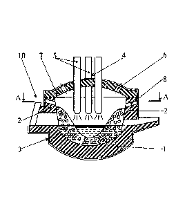
The EAF for this claimed steel-melting method consists of the bottom (1),
lined with high-resistant
materials, walls (2) and housing (3) with apertures (4) to insert electrodes
(5), hole (6) to supply
granular materials, involved in steel melting, and dome-shaped removable roof
(7) with electrode
holders (conditionally not shown) and a three-electrode unit (5). Walls (2)
are designed with at least
6
three apertures (8) along the perimeter to supply OCM into the central zone
(9) of the furnace,
located below the upper mark (10) of the housing (3) at 0.2¨ 1.0 m. It is
recommended to distribute
apertures (8) along the perimeter of the walls (2), advantageously positioning
them between two
neighboring electrodes (5) (or oriented in the direction between two
neighboring electrodes (5)). This
is done to eliminate the possibility of bombarding supplied OCM bricks with
electrodes (5), which
could damage them, as well as to eliminate the possibility of loading OCM
beyond the central zone
(9) of the furnace, restricted by diameter D, since in this case additional
energy will be required for
its melting, which leads to the zone's overheating, directly adjacent to
electrodes (5).
Let's analyze the significant points of inventions.
The central zone (9) in EAF differs from other workspace volumes by an
enormous amount of
emitted heat energy and its maximum concentration, reaching 10 MVA/m3 in a
current generation of
ovens, as well as high melting temperature level at 4,000¨ 15,000 K and a
very significant melting
temperature of an initial charge and final product (liquid metal), no more
than 1,700 C, Due to
these factors, the melting properties of all loaded materials into the
furnace, included OCM chunks,
in the burning zone of electric arcs (5) and zones beyond its boundaries and
at the edges of the
furnace, radically differ.
In the first case, melting is performed with excessive energy consumption and
at very high
temperatures, significantly exceeding melting temperatures of initial
materials and final product (i.e.
steel). One of the consequences of such process is incomplete heat absorption
of supplied energy,
significant heat loss and overconsumption of electricity.
In the second case, which differs from the first case, the transition of solid
charge components into a
liquid state, while forming, respectively, metal and slag, is performed with
heat deficiency and
operating temperatures that do not exceed temperatures of metal and slag, i.e.
1,700 C.
The proposed method, in comparison to others, is based on loading some part of
OCM together with
scrap even before the melting process, and, as a rule, a more significant part
of CCM is loaded into
the burning zone of arcs during the melting process, when more electricity is
supplied to the electric
furnace. Supplied materials significantly increase heat absorption of the
charge, thus lowering heat
loss and energy consumption.
A special characteristic of the furnace's central zone energy along with a
change in the process of
supplying OCM to the furnace predefines an exceptionally fast melt of OCM
solid chunks and their
transition to a liquid phase. Due to that, basic OCM components ¨ iron oxides
of a hard oxidizer and
carbon, which is contained in the carburizer, react with each other, which
happens with quite high
specific speed approximately at 5 ¨ 40 kg/(s.m3). Products of this reaction of
carbon oxidation and
iron reduction are metallic iron and carbon monoxide.
7
CA 2935206 2018-07-30
CA 02935206 2016-06-27
The first one flows down into a metal bath, and the latter one serves as a
source of additional heat
supply in the furnace due to afterburning of CO and CO2, thus reducing
specific consumption of
electricity to me.t metal charge.
The heating and melting of OCM is done due to an additional accumulation of
part of the heat,
which was not absorbed by the charge due to its limited ability to consume
entire energy and thus
:nes heat loss. This circumstance ensures a reduction in specific consumption
of electricity to melt
the charge.
The proposed method also ensures a fast and complete reduction of iron from
its oxides by carbon
from OCM and increase extraction of iron and output of useful one.
In this case, OCM melting also leads to the formation of liquid slag phase,
which in proves arc
burning and stability of supplying energy to the furnace. This results in
additional electricity savings,
which is attained due to a reduction in energy loss while arcs are burning.
Current EAFs have a sole, so-called õfifth" hole din the furnace roof to
supply granular materials
during the me ting process. Switching to adding materials during the melting
process requires
changes in the current EAF design to create a capability for continuous and
even supply of required
materials, including OCM, through three or more apertures 8 in walls 2,
placing them in the upper
part of the furnace housing 3 below the level of the upper mark 10 at 0.2¨ 1.0
m, This allows
supplying OCM from the very beginning of the melting process at any bulk
density of scrap metal,
as well as makes it possible to control the consumption of OCM in a wider
range and much
smoother.
The main feature of the melting process in EAF is the maximum amount of
supplied electricity for
the purpose of the fastest charge melting and reduction of continuity of this
stage, which takes most
of the time of the electric melting process. EAFs, especially the latest
generation, have a high-
powered transformer, reaching up to 1,500 KVA per ton of steel, which is why a
significant amount
of highly concentrated energy is added to the charge. This amount
significantly exceeds an ability of
the solid charge to accumulate and absorb the supplied heat. Due to the
limited ability of the charge
to absorb tee supplied energy, a significant part of it is used inefficiently,
being spent to evaporate
some parts of the metal, overheating the charge, metal and gases, as well as
an increased
emission to the roof 7 and walls 2 of the furnace etc. These factors increase
heat loss and energy
consumption and reduce heat efficiency of EAF during the melting process.
OCM within the charge supplied during the melting process, fills up the space
inside the layer of
melting charge, thus increasing its bulk density. Since they are relatively
small in size, these
materials have a more developed heat transfer surface in comparison with metal
charge chunks.
Furthermore, OCM pellets are related to, in comparison to scrap metal, to thin
bodies and therefore
8
CA 02935206 2016-06-27
have a faster heating speed, and respectively, less time to melt. Due to these
factors, OCM
increase an accumulating capability of the charge and its melting speed, thus
increasing the level of
energy absorption, discharged during arc burning and reducing its loss.
Respectively, this reduces
specific consumption of electricity and melting duration.
3esides the physical influence on heat exchange in the arc burning zone, which
is due to increased
heat absorption from burning arcs, OCM has an additional cooling effect, based
on a chemical
reaction between carbon and iron oxides of OCM. This reaction is endothermic
anc therefore
additionally cools the zone, where these materials are located, thus
increasing the absorption
speed of heat that is supplied to this zone. Therefore. OCM application in EAF
melt, by supplying it
into tne central zone 9 of the furnace, leads to a transfer of some heat to
the reaction of carbon and
iron oxides interaction. Thus a reduction of irreversible heat loss and
specific consumption of
electricity is achieved. The described effect is related to a chemical cooling
of burning arc zone and
adds a purely physical effect of OCM on the temperature in that zone,
increasing the cooling effect.
The endothermic reaction is related to the reaction of reduction of iron from
its oxides by carbon
and has significant heat consumption. However, in the claimed method, losses
for this reaction is
ensured by the heat, taken from the energy, discharged from the furnace and
considered a loss..
This eliminates additional heat loss when using OCM.
Iron and iron monoxide are the products of the interaction reaction of carbon
and iron oxides in
OCM, supplied during the melting process. The iron, obtained from OCM, is
transferred to a metal
bath, thus increasing the iron output. Furthermore, it has an original
characteristic and distinguished
by its increased purity in relation to remaining elements, such as Cu, Sn, Mo,
Cr, NI, etc.
Significantly nigh temperatures in tne central zone of the furnace, developed
heat excnange surface
of OCM chunks (pellets), large reaction contact surface of the carburizer, as
well as high intensity of
heat transfer ensures the required and sufficient conditions for this
reaction, including a complete
reduction of iron.
The resulting carbon monoxide is a source of additional heat, emitted from
within of the charge
chunk. Filtered through the layer of a melting charge chunk, it is burnt until
it becomes CC,
dissipating 6.55 kWh of heat per every kilogram of carbon, contained in OCM.
The presence of the
solid charge, its develcped surface, relatively low temperatures, as well as a
combination of CO
formation zones, its additional burning and heat absorption create conditions
for more complete CO
burning until it becomes CO2 within the charge and increased heat transfer of
burning of
surrounding materials. These values significantly exceed similar ones of known
methods, where
after-burning and heat transfer is done at the beginning of the melting
process, when the bath is in
a hybrid state and covered in foamed slag. These factors significantly worsen
conditions for after-
9
CA 02935206 2016-06-27
burning and heat recycling.
From the above, it leads that OCM usage during the melting process, based on
its supply to furnace
during the melting process, significantly changes behavioral characteristics
during electric melting
process of these materials and EAF energy in general. After supplying OCM to
the high-
temperature zone and its subsequent heating of material chunks, iron reduction
reaction from its
oxides by carbon, contained in OCM, begins and iron output increases. Due to
that, physical and
chemical cooling of the burning zone is achieved. It significantly increases
the level of heat
absorption and eliminates its loss. Carbon monoxide is after-burned to CO2
during the filtration
process thrcugh the charge volume. Due to this, a combination of CO formation
zone, its after-
burning to CO2 and heat absorption is achieved, which significantly increases
after-burning
efficiency and carbon as energy carries in general, thus reducing consumption
of e ectricity and
melting time.
This is one of the advantages of the proposed method compared to known ones,
where OCM
begins to actively melt only at the conclusion of the melting process. At that
moment, a hybrid state
metal bath is formed in the furnace, covered by relatively cold foamed slag.
Therefore, the after-
burning process of CO to CO2 and heat transfer to the furnace bath passes in
unfavorable
conditions. Due to that, the resulting effect of using carbon is significantly
reduced and does not
exceed 3.1 -- 3.8 k\Alh/kg of carbon in comparison with 4.5 ¨ 4.9 kWh/kg in
the proposed method.
Thus, the proposed method of melting steel, based on the application of a
special system to load
OCM, significantly improves the energy consumption during the melting period,
thus ensuring
significantly lower consumption of electricity.
¨ 90 % of values are defined by wide boundaries of change in specifc power of
the furnace
transformer and cooling effect of OCM chunks of various content. Depending on
the ratio of these
parameters, an amount of OCM supplied during the melting process, may change
by 10 ¨ 90%
from their consumption per melt. In case where that amount is less than 10%,
the achieved effect is
reduced, limiting parameters of the proposed method_ Wnen OCM consumption
during the melting
process is more than 90%, the efficiency of the proposed method is also
reduced. it is defined, in
this case, the amount of OCM, supplied along with scrap, does not ensure the
necessary amount of
carbon monoxide, which weakens the mixing intensity of metal bath and prolongs
the melting
process. Besides that, a limited amount of the forming monoxide reduces the
amount of heat
supplied to melting materials and hybrid state bath, Both factors, taken
together, result in increase
of energy consumption per charge melt. Therefore, the referred interval of OCM
consumption
during the melting process, which equals to 10 ¨ 90% ensures an achievement of
maximum
specific heat consumption per charge melt.
CA 02935206 2016-06-27
A typical size of OCM chunks in the range of 5 ¨ 80 mm represents an average
of three sizes of a
single chunk. This chunk size range was taken from an assumption of a
possibility :o place them in
open spaces of metal scrap and capability to supply OCM through apertures in
walls 2 of furnace
housing 3. When chunks are less than 5 mm, an effect of their emergence
through chunks of scrap
into the lower part of the metal load and their exit from the melting zone is
observed. This leads to
OCM accumulation in charge layers, adjacent to the bottom 1, and slows down
their melting,
shifting it to the conclusion of the charge melt. Therefore, lowering the OCM
chunk size to less than
mm is not preferred. Chunks more than 80 mm in size have more tendency to hang
ups and
difficult to supply into the furnace. Therefore, further size increase is not
feasible.
As a whole, a combination of above parameters, namely supply of 10¨ 90% of CCM
during the
melting process with individual chunk size in the 5¨ 80 mm range, ensures
thorough melting of
these materials at the beginning melting stage, with quite high speed and due
to heat, which is lost
due to the charge's inability to absorb all of the supplied heat from electric
arcs. Fwthermore, a total
reduction of iron, contained in oxides of solid oxidizers, is achieved. Thus
the iron output increases.
A significant value is provided by an earlier, from the beginning of melt,
formation of carbon
monoxide, which is formed along with iron as a reaction product of carbon and
oxygen of iron
oxides from a solid oxidizer. Thus, the formed amount of carbon monoxide,
reaching 600 m3/t of
material, plays a positive role. Monoxide plays the role of an additional
energy carrier, since it is
after-burned to 002, emits an enormous amount of heat ¨6.55 kWh per one
kilogram of carbon.
The presence of solid chunks of charge improves after-burning heat absorption
in comparison with
known methods ¨ 60 ¨ 80% instead of 30 ¨ 50%, thus giving an additional
electricity savings.
Introduction of monoxide into the furnace's atmosphere decreases the oxygen
content and, as a
whole, an oxidizing potential of the gaseous state in relation to toe metal
scrap surface, thus
additionally reduclng iron oxidation of metal scrap and increasing the iron
output from toe metal
charge.
OCM, according to the claim, is supplied to the central zone 9 of the furnace
with sizes, not
exceeding D-,--(dp+3.5 dEL), whose area is no more than 30% of the total cross-
sectional area of the
furnace at the roof level.
A selection of this parameter is defined by specific energy of EAF, which
means that all electricity
transition to heat and heat dissipation happens within the central zone 9 of
the furnace, comparable
in size to electrode 5 circle diameter dp. For modern high-powered furnaces of
the latest generation,
an absolJte value of tois parameter is 1.3 ¨ 1.6 m. A presence of a highly
concentmted heat source
at the furnace center, predetermines an advantageous melting of solid
materials of a metal load in
the arc-burning zone. Peripheral zones of the charge melt significantly later,
after thorough melting
11
CA 02935206 2016-06-27
of wells and formation of a unified melting zone. Especially high
concentration of energy in the arc
burning zone and its adjacent zones explains the necessity to supply OCM
exactly into the central
zone 9 of the furnace, which is located below electrodes 5 and to the sides of
them.
if supp:y zone size does not the exceed the value of D=i(dp+3.5 deL), then the
supplied OCM get into
the zone of the highest temperatures and maximum concentration of energy.
Thus, an earlier
melting of OCM and a faster completion of the reaction between carbon and iron
oxides of a solid
oxidizer, whose target product ,s iron, reduced by carbon from its oxides and
carbon monoxide, is
ensured. The latter is used as a source of additional heat in the form after-
burning energy and
factors which reduce an oxidizing potential of the gaseous state of EAF and
thus increasing the
iron output from the charge. The recommended interval of the specific feed
speed of OCM to the
furnace is 0.5- 10.0 kg/min at 1 MVA of the transformer power. When the
loading speed is below
0.5 kg/min at 1 MVA, the achievable effect in relation to a reduction in
energy consumption and
incifease in iron output is significantly reduced and, therefore, the further
reduction of the value is
not feasible. When the OCM loading speed exceeds 10 kg/min at 1 MVA, an
excessive cooling of
arc burning zones and adjacent zones is observed. This leads to a prolonged
melting process and
increase in energy consumption. Besides that, there is a danger of
incompletion of the main OCM
reaction, i.e a reaction between carbon and iron oxides, which determines the
efficiency of
application of these materials. Thus, the applicable range for loading speed
is 0,5 - 10.0 kg/rnin
which is the most rational solution.
The main dominating characteristic of OCM is the carbon- oxygen (0/0) ratio,
which generalizes a
joint impact on efficiency of application of these composite materials and
selection of their content.
The carbon to oxygen ratio in OCM is selected in the range of 0,15 < 0/0 <
5.00.1f the C/O ratio in
OCM is below 0.15, then the cooling effect of this material will be close to
maximum, which equals
to the cooling capability of the solid oxidizer. One of its consequences is
the necessity to decrease
the OCM amount per melt, which reduces the efficiency of the proposed method.
Thus, a C/O ratio
reduction to below 0.15 is not preferred.
In those cases, when 0/0 ratio is above 5.00, the cooling capability of the
material will start to
decrease dramatically. The cause of this is a high carbon content, discharged
from OCM into a
metal bath, and leads to an excessive metal carbonization. Thus, increasing
the C/O ratio to above
5.00 is irrational. Therefore, both 0/0 ratios, below 0.15 and above 5.00, are
not preferred.
The OCM component content limits and contents of materials are determined by
the following
method. If it consists of less than 40% solid oxidizer, and the carburizer
content is more than 60%,
then the entire oxygen of iron oxides of the solid oxidizer is completely
consumed to oxidize parts of
carbon, while the remaining significant amount of carbon is introduced to the
bath, thus carbonizing
12
CA 02935206 2016-06-27
it. Furthermore, the amount of carbon, introduced to the bath, is quite high.
increas.ng the carbon
content decreases the cooling effect of OCM on the arc burning zone
temperature, as well as it
requires additional consumption of oxygen and electricity, thus prolonging the
oxidation process
and the whole melting process, in general. At the same time, metal
dephosphorization conditions
worsen due to a reduction of the iron oxide amount in slag. Thus, reducing the
solid oxidizer content
to below 40% and increasing carbon-contaning reagent to above 60 % is not
feasible. At an
increased content of solid oxidizer in OCM of above 95% and, respectively, a
reduction of the
carburizer content to below 5%, an amount of iron oxides, acting as oxygen
donors, significantly
exceed their amount, which are required to remove all carbon from OCM.
Excessively high content
of the solid oxidizer increases the cooling effect of OCM to the level nearing
the pure form of the
solid oxidizer and equals to 3¨ 4 units of the cooling capability of scrap
metal. This significant)/
reduces OCM consumption per melt. The resulting excess of iron oxides is sent
to slag, increasing
oxidation and mass of sag. These factors negatively impact electric melting
parameters,
decreasing iron output, increasing oxygen content in the final metal product,
increasing
consumption of deoxidants, increasing contamination of stee by oxygen content,
as well as
reducing the furnace lining stability. All of this restricts the limits of
oxidizer and carburizer content in
OCM to 90 and 5%, respectively. An adhesive in the OCM content in the amount
oil ¨ 10% above
100% of the total mass of the carburizer and solid oxidizer, ensures the
proper mechanical stability
of pellets and does not significantly impact the melting process.
OCM may contain iron-containing metal particles in the amount of 5 ¨ 30%. The
presence of such
particles significantly speeds up the main reaction between carbon and hard
oxidizer that happens
within OCM, when it is heated and melted. The presence of metal particles
within OCM increases
the reduction of iron from its oxides by carbon and the speed of this process.
At their relatively low content within OCM, below 5%, the benefit of its
impact on the reaction
kinetics is weakened. Furthermore, the positive results do not outweigh
complications in tecnnology
to obtain chunks of material. Increasing the content of metal particles within
OCM to above 30%
results in a significant increase in adhesive consumption due to the reduction
in stability of OCM
chunks, as well as due to process complications, related to OCM chuni<s.
Therefore this parameter
is optimal at 5 ¨ 3% range.
OCM may contain 0.1 ¨ 10.0% of slag-forming components. Their content within
OCM ensures an
earlier formation of liquid sag, during the melting process, and as shown in
experiments, increases
the stability of electric arcs burning and reduces their energy loss.
Furtnermore, a fast formation of
slag improves conditions to remove phosphorus after the melting process is
complete. A reduction
in slag-forming materials to below 0.1% is not preferred, since it reduces the
efficiency of its impact.
13
CA 02935206 2016-06-27
increasing those materials to above 10.0% is also not preferred, since it
reduces the relative
content of main components of OCM, i.e. carbon and iron oxides 0.1 ¨ 10.0%
content is the most
optimal range.
The existing EAFs have only one hole to supply bulk materials during the
melting process, thiough
the furnace dome. For modern furnaces that are able to operate with
significantly large amount of
materials, suppled during the melting process, one hole may not be sufficient.
The situation is
further complicated by the tendency to continuously reduce the bulk density of
the scrap metal,
vvh ch leads to completely filling the whole space of the furnace, almost up
to the dome 7. Naturally
this leads to the reduction in gaps in the metal load and complicates an
ability to suppy OCM at the
initial stage of the melting process, thus I.miting its consumption. The
solution to this problem is to
increase the throughput by increasing the number of apertures, namely in walls
2 of the furnace
housing 3, placed along the perimeter with strategic positioning between two
neighboring
electrodes 5 and having at least three times the number of electrodes 5, and
their positions below
the level of the upper mark 10 of the housing 3 at 0.2 ¨ 1.0 m. This allows
inputting OCM from the
beginn ng of the melting process at any bulk density of the scrap metal and
makes it possible to
evenly control the OCM consumption in a wide range. Furthermore, electrodes 5
are not damaged
by the ncoming flow of OCM pellets, and the latter are guaranteed to get to
the central zone 9 of
the furnace. Thus the even distribution and thorough melting of materials,
without the formation of
conglomerates of accumulated unmelted OCM, is ensured.
The steel-melting method is EAF is performed the following way.
After completing tne removal of metal and slag from EAF, its workspace is
loaded, thus bringing the
furnace to an initial state. The first bucket load consists of scrap metal and
chunks (pellets) of OCivl,
having the chunk size in the range of 5 ¨ 80 mm, with the bonding base of 1 ¨
10% Poland
cement, made by vibration molding, for example. The proper amount of OCM is
taken, calculated
by 10¨ 90% from the total consumption per melt. Power, fuel, gaseous oxygen
and flux are
supplied. At the same time and in parallel, from the moment of charge melting,
CCM is supplied into
the furnace workspace through a number of apertures 8 in walls 2 of furnace
housing 3 at specific
speed of 0.5 ¨ 10 kg/mm n at 1 MVA of estimated power of the transformer.
These chunks partially fill
up the gaps that remain in scrap metal. The scrap metal that is currenty used
has a reduced bulk
mass, approximately 0.5 t/m3. Due to that, some gaps within scrap metal exceed
90% and take up
a prevaling part of the total charge volume. The presence of free cavities
within a layer of the initial
metal load ensures the placement of incoming OCM in its volume.
At a high bulk density of scrap metal, it is preferable to supply OCM at 1 ¨ 2
minutes after the
beginmng of the melting process. Thanks to this, a part of the solid charge
already melts. thus
14
CA 02935206 2016-06-27
freeing some workspace in EAF and creating additional free spaces between the
scrap metal
surface and the furnace dome 7.
The incline angle to supoly materials that flow through apertures 8 in walls 2
of the EAF housing 3
in combination with chunks of OCM, improves the ability to make it to the
central zone 9, a part of
which serves as an arc burning zone. limiting the size to D=(dp+3.5 cIFJ.)
maximum, which exceeds
30% of the cross-sectional area of The furnace's workspace. Thus, the supply
of OCM into the
central zone 9, located below hot electric arcs and restricted from sides by
walls of unmelted
charge, is ensured.
The consumption rate of supplied materials is 0.5 ¨10.0 kg/min at 1 MVA power
crf the transformer
of the furnace, based on maintaining the feed speed at the level that
corresponds to their speed
flow, or somewhat below it, which is determined by the amount of supplied
power. Gradually, the
material consumption is increased. This is done as the charge continues to
melt, as cavities (wells)
form within a metal load layer, free from the melted charge and form below
electrodes 5 in the
unified melting zone. After the fir-st stage, i.e. melting the part of the
first bucket, namely 50-65% of
the metal load, the furnace is turned off and OCM supply is stopped. Then, the
second bucket of
scrap metal is loaded and the furnace is turned on and OCM is supplied again.
The supply of these
materials stops after freeing up walls 2 from the solid charge, which screens
furnace lining from
arcs, and the formation of the hybrid state metal bath with scrap metal chunks
immersed in it. This
corresponds to the final stage of the melting process, which passes at the
flat surface condition of
the bath, in conditions of direct emission of arcs on walls 2 and furnace dome
7. After that, the
melting process continues along the standard process, similar to known melting
methods.
At the beginning of the melting process, the supply of OCM loads to the charge
is based on the
presence of the large number of gaps in it, which are the majority of the
charge volume and the tota
workspace of EAF. Further melting of the initial solid charge, based on scrap
metal, which has a
relatively low bulk density, around 0.4 ¨ 0.6 t/m3, is followed by a formation
of free spaces within
scrap metal layer, already mentioned above as wells. The latter ones are
cavities through the whole
metal charge, from the dome 7 to the bottom 1. Their shape closely resembles a
cylinder, whose
walls consist from fragments of materials that form the initial metal load.
Wells form due to the
transition of the solid charge, located below electrodes 5 and to their sides
in a molten state and
fowing the formed melt to the lower part of the furnace, down to bottom 1.
Thus, the furnace
workspace beg ins to free itself from charge chunks and forming cavities
within the metal load, free
of solid materials. This eases conditions to supply OCM to the workspace and
allows to increase its
consumption.
After electrodes 5 pass over all initial metal load and after they are lowered
to their lowest position
CA 02935206 2016-06-27
and arc burning transition to the operating mode, in the hybrid state bath,
located on the furnace
bottom 1, the melting process of charge chunks, which form side walls of
wells, and expansion of
initially formed free gas cavities within the metal load, begins.
Low bulk density of scrap metal predetermines a relatively small diameter of
wells at the moment of
their formation, expressed by dK = 1.5dEt. Supply and/or presence of OCM
chunks within the metal
charge increases the ratio of well diameter to electrode diameter. When the
relative diameter of
wells reaches dK/dEL = 2 or more, then the formed wells combine into one
single melting zone,
located in the central zone 9 of the furnace, below electrodes 5. This zone,
from its sides, is formed
by yet unmelted charge chunks, which are, in turn, supported by walls 2 of EAF
housing 3.
As a result of partial melting of the solid charge, located below electrodes
5, some workspace is
freed from scrap metal. It significantly improves OCM supply to the furnace
and increases the feed
speed, as well as ensures their ingress, supply and their priority placement
at the surface of the
liquid metal bath, formed in the process of melting.
After loading the second bucket, OCM chunks appear within the metal load at
approximately at the
middle of the workspace of the furnace. Furthermore, they are in the center of
the moving path of
electrodes 5. This creates the required and sufficient conditions for the
efficient usage of OCM
potential, from a point of view of the reaction of carbon and oxygen of the
solid oxidizer, contained
in this material, as well as from a point of view of after-burning of CO to
CO2 and absorpt'on of that
heat by melting materials and metal bath. At the same time, this speeds
carbonization of the bath,
which, in turn, speeds uo the melting process and reduces energy consumption
Thus, the supply of some OCM pellets during the melting process significantly
changes the melting
technology for tne better and increases efficiency of its application.
The carbon to oxygen ratio, supplied by iron oxides of the solid oxidizer, is
selected and maintained
in the range of 0.15< C/O <5.00. The efficiency of the proposed method
increases when metal
particles, containing 5 ¨ 30% of iron, are added to OCM content. A presence of
metal iron reduces
the temperature of the beginning of the reaction of carbon and iron oxides, as
well as speeds up the
flow of this reaction. In turn, it increases the reduction of iron speeds up
the formation of carbon
monoxide. The earlier formation of this gas Improves the conditions for after-
burning and heat
transfer to melting materials of the metal load, as well as increases the
duration of heat exchange of
charge chunks with heat, formed in the after-burning process of CO to 002.
An increase in efficiency of the proposed method is helped by adding slag-
forming components of
oxides and/or fluorides of chemical elements to OCM content, which, in
comparison to iron, are
closer to oxygen at temperatures above 1,550 C, in the amount of 0.1 ¨ 10%
from the total mass
of the material.
16
CA 02935206 2016-06-27
As a result of applying this group of inventions, steel-melting methods and
EAF were created for its
implementation, which, in the end, significantiy lowered the specific
consumption of electricity to
molt the metal charge and increased iron output from OCM, as well as increased
their relative
amount in the total mass of the charge.
17