Note: Descriptions are shown in the official language in which they were submitted.
CA 02935228 2016-07-06
TSN201503192
TFN150459
1
METHOD FOR MANUFACTURING ROTARY ELECTRIC MACHINE ROTOR
BACKGROUND
1. Field
[0001] The disclosure
relates to a method for manufacturing a rotary electric
machine rotor, which includes magnet core blocks and in which the plural
magnet core
blocks are integrated, the magnet core block being formed by integrating a
magnet and a
core block element that is made of a magnetic material.
2. Description of Related Art
[0002] Conventionally, a
configuration of a rotary electric machine rotor that
uses a rotor core made of a magnetic material has been known. A rotor, in
which
magnet holes that penetrate in an axial direction are formed at plural
positions of the rotor
core in a circumferential direction and a magnet is disposed in each of the
magnet holes,
has also been known. In order to reduce core loss of the magnet, there is a
case where
the magnets, which are disposed at the plural circumferential positions, are
each disposed
separately as the plural magnets in the axial direction of the rotor in such a
configuration.
[0003] In Japanese Patent
Application Publication No. 2007-282358 (JP
2007-282358 A), it is described to form a stacked body by stacking plural core
plates that
are made of electromagnetic steel sheets and to form plural magnet holes
around a shaft
hole at the center of the stacked body. A magnet is inserted in each of the
magnet holes,
a portion above each of the magnets and a periphery of each of the magnets are
filled
with a resin member, and the magnets and the stacked body are integrated, so
as to form a
magnet core block. Then, the rotor is formed by stacking and fixing the plural
magnet
core blocks.
[0004] Japanese Patent Application Publication No. 2007-215357 (JP
2007-215357 A) discloses a configuration, in which the plural magnets are
inserted in the
magnet hole of the rotor core in such a way that the magnets are aligned in
the axial
direction. In this configuration, in order to promote an inflow of a resin
between the
CA 02935228 2016-07-06
TSN201503192
TFN150459
2
plural magnets, a chamfering portion or a counterbore portion is formed at an
inner end
of each of the magnets.
[0005] In a
process of forming the magnet core block as in the method for
manufacturing the rotor described in JP 2007-282358 A, the portion above the
magnet is
filled with the resin member. Thus, a resin portion in the magnet hole is
largely exposed
to an outer side at an end of a resin injection side of the magnet core block.
Accordingly, in a state where the rotor is formed by stacking the magnet core
blocks, a
surface of the resin portion in the magnet hole is largely exposed to the
outer side at one
end in the axial direction of the rotor. In such a configuration, there is a
possibility that
stress is generated in the resin portion by repeated excess temperature
changes during use
of the rotor or by rotation of the rotor and the resin portion is cracked. For
example, a
thermal expansion difference is generated between the magnet and the resin
portion
during a temperature increase. Thereafter, the excess stress is generated in
the resin
portion for covering the magnet at a position near a core end surface due to a
temperature
decrease. As a result, the resin portion is possibly cracked. If the cracked
resin portion
is scattered peripherally during the rotation of the rotor, it may lead to
performance
degradation of peripheral parts or a degraded force of the resin portion for
fixing the
magnet. Meanwhile, as for the rotor that is manufactured by the method for
manufacturing described in JP 2007-215357 A, cracking of the resin portion can
be
suppressed. However, the resin is injected in a state where the two magnets
are
separated to both sides in the axial direction within the magnet hole, and
thus the
positions of the magnets have to be managed highly accurately. As a result,
there is a
possibility that productivity is decreased and manufacturing cost is
increased.
SUMMARY
[0006] The
present disclosure provides a method for manufacturing a rotary
electric machine rotor for realizing a structure that can achieve favorable
productivity and
suppress scattering of a resin portion in the rotary electric machine rotor in
which plural
magnets are disposed separately in an axial direction.
CA 02935228 2016-07-06
TSN201503192
TFN150459
3
[0007] A
method for manufacturing a rotary electric machine rotor according to
the present disclosure includes: forming core block elements that are made of
a magnetic
material, each of the core block elements has a shaft hole at the center and
plural magnet
holes around the shaft hole. Furthermore, the method for manufacturing
includes:
inserting magnets in corresponding one of the magnet holes, an axial length of
each of the
magnets is shorter than an axial length of each of the magnet holes. Moreover,
the
method for manufacturing includes: forming magnet core blocks by injecting a
molten
resin into each of the magnet holes from above the magnet, solidifying the
molten resin,
and thereby forming a resin portion so as to integrate each of the core block
elements and
the magnets, each of the magnet core block elements has axial end surfaces
that are first
end surface and a second end surface, the first end surface is on an opposite
side from the
second end surface, the molten resin is injected at the second end surface,
and end
surfaces of the magnets being exposed on the first end surface. Furthermore,
the
method for manufacturing includes: forming a rotor by stacking and integrating
a plural
magnet core blocks such that center axes correspond to each other, the plural
core blocks
being stacked such that the first end surfaces of the two magnet core blocks
that are
disposed at both ends in an axial direction constitute end surfaces at both
ends of the rotor
in the axial direction.
[0008]
According to the method for manufacturing a rotary electric machine
rotor according to the disclosure, the plural magnet core blocks are stacked
and
integrated such that, in the two magnet core blocks that are disposed at both
of the ends
of the rotor in the axial direction, the end surfaces on exposing sides of the
magnets
constitute the end surfaces at both of the ends of the rotor in the axial
direction. In
addition, ends on resin injection sides of the two magnet core blocks at both
ends are
disposed on an inner side of the rotor in the axial direction. In this way,
favorable
productivity of the rotor, in which the plural magnets are disposed separately
in the axial
direction, can be achieved, and a structure capable of suppressing scattering
of the resin
portion can be realized.
CA 02935228 2016-07-06
TSN201503192
TFN150459
4
BRIEF DESCRIPTION OF THE DRAWINGS
[0009] Features, advantages, and technical and industrial
significance of
exemplary embodiments of the disclosure will be described below with reference
to the
accompanying drawings, in which like numerals denote like elements, and
wherein:
FIG 1 is a cross-sectional view of a rotary electric machine that includes a
rotary
electric machine rotor manufactured by a method for manufacturing of an
embodiment
according to the disclosure;
FIG. 2 is a cross-sectional view of the rotary electric machine rotor
manufactured by
the method for manufacturing of the embodiment according to the disclosure;
FIG. 3A is a cross-sectional view that shows the method for manufacturing the
rotary electric machine rotor shown in FIG. 2;
FIG. 3B is a cross-sectional view that shows the method for manufacturing the
rotary electric machine rotor shown in FIG. 2;
FIG. 3C is a cross-sectional view that shows the method for manufacturing the
rotary electric machine rotor shown in FIG. 2;
FIG. 3D is a cross-sectional view that shows the method for manufacturing the
rotary electric machine rotor shown in FIG. 2;
FIG 4 is a cross-sectional view of a rotary electric machine rotor
manufactured by
another example of the method for manufacturing of the embodiment according to
the
disclosure; and
FIG. 5 is a cross-sectional view of a half portion of a magnet core block that
is
formed in a process of forming the magnet core block in the other example of
the method
for manufacturing of the embodiment according to the disclosure.
DETAILED DESCRIPTION OF EMBODIMENTS
[0010] A description will hereinafter be made on an embodiment of
the
disclosure by using the drawings. Shapes, materials, and number of units,
which will be
described below, are merely illustrative and can appropriately be changed in
accordance
with a specification of a rotary electric machine. In the case where plural
embodiments,
CA 02935228 2016-07-06
TSN201503192
TFN150459
modified examples, and the like are provided in the following description,
those can
appropriately be combined and implemented. In the following description,
equivalent
components are denoted by the same reference numeral in all of the drawings.
In
addition, in the description of this section, reference numerals that are
mentioned earlier
5 are used upon necessary.
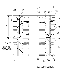
[0011] FIG. 1
is a cross-sectional view of a rotary electric machine 50 that
includes a rotary electric machine rotor 10 manufactured by a method for
manufacturing
of the embodiment. FIG. 2 is a cross-sectional view of the rotary electric
machine rotor
manufactured by the method for manufacturing of the embodiment.
10 [0012] The rotary
electric machine rotor 10 is used to form the rotary electric
machine 50. For example, the rotary electric machine 50 is a synchronous motor
with a
magnet that is driven by a three-phase AC current. For example, the rotary
electric
machine 50 is used as a motor for driving a hybrid vehicle, as a generator, or
as a motor
generator that has functions of both of those. The rotary electric machine
rotor 10 will
hereinafter be described as the rotor 10.
[0013] The
rotor 10 is a cylindrical member and is formed by stacking and
integrating two magnet core blocks 11. During use of the rotor 10, a rotary
shaft 51 is
inserted in and fixed to the rotor 10. In a state where the rotor 10 is
disposed in a case
52, the rotary shaft 51 is rotatably supported at both ends by the case 52. In
the case 52,
a cylindrical stator 53 is fixed on a radially outer side of the rotor 10. The
rotary electric
machine 50 is formed in this way.
[0014] As
shown in FIG. 2, each of the magnet core blocks 11, which form the
rotor 10, includes a cylindrical core block element 12 and magnets 30 as
plural
permanent magnets that are fixed to the core block element 12. The core block
element
12 is a stacked body that is formed by stacking plural core plates 13, the
core plate 13
being made of a steel sheet as a magnetic material. A shaft hole 14 is formed
at the
center of the core block element 12, and plural magnet holes 15 are formed
around the
shaft hole 14. The magnet hole 15 has a rectangular shape when seen from one
side in
CA 02935228 2016-07-06
TSN201503192
TFN150459
6
an axial direction. The plural magnet holes 15 are disposed along a
circumferential
direction of the core block elements 12 at regular intervals.
[0015] The
core plate 13 is formed by punching the thin steel sheet with a
thickness of 0.5 mm or smaller, for example, in an annular shape. The core
plate 13 is
formed with a shaft hole at the center and plural peripheral magnet holes by
the punching.
The core block element 12 is formed by stacking the plural core plates 13, the
number of
which is set in advance. The shaft hole 14 of the core block element 12 is
formed by
connecting the shaft holes of the plural core plates 13 in the axial
direction. The plural
magnet holes 15 of the core block element 12 are formed by connecting the
plural magnet
holes of the plural core plates 13 in the axial direction. The magnet 30 is
inserted in
each of the magnet holes 15.
[0016] The
magnet 30 is in an axially elongated cuboid shape, and a
magnetization direction thereof corresponds to a radial direction of the rotor
10. An
axial length L1 of each of the magnets 30 is shorter than an axial length L2
of the magnet
hole 15. In a state where the magnet 30 is disposed in the magnet hole 15, the
magnet
hole 15 is filled with a resin, and the resin is solidified. In this way, the
core block
element 12 and the magnet 30 are integrated. A resin portion 31, in which the
resin is
solidified, fixes the magnet 30 in the magnet hole 15.
[0017] A
thermosetting resin can be used as the resin portion 31, and a molten
resin 46 (see FIG. 3C) as a resin material that is melted by heating is
injected into the
magnet hole 15 from the above and is hardened. In this way, a portion above
the
magnet 30 and a periphery of the magnet 30 in the magnet hole 15 are filled
with the
resin portion 31. Then, the magnet 30 and the core block element 12 are
integrated, and
the magnet core block 11 is formed.
[0018] The rotor 10 is
formed by stacking and integrating the two magnet core
blocks 11, which are formed as described above, in the axial direction. At
this time, the
shaft holes 14 of the core block elements 12 are connected in the axial
direction. The
rotary shaft 51 (FIG. 1) of the rotary electric machine 50 is inserted in the
connected shaft
hole 14. The plural magnet holes 15 of the one core block element 12
respectively
CA 02935228 2016-07-06
TSN201503192
TFN150459
7
correspond to those of the other core block element 12. Here, paired magnet
holes of
the core block element may be disposed at plural circumferential positions of
the core
block element, and the two magnet holes in each of the pairs may be disposed
in a
substantially V shape.
[0019] The two magnet
core blocks 11 are disposed at both ends of the rotor 10
in the axial direction. The two magnet core blocks 11 are integrated such that
first end
surfaces Al, B1 on sides where the magnets 30 are exposed constitute end
surfaces at
both of the ends of the rotor 10 in the axial direction. More specifically, of
the two
magnet core blocks 11, the first end surface A 1 on the exposing side of the
magnet 30 of
the one magnet core block 11, which is disposed at one of the ends (an upper
end in FIG.
2) of the rotor 10 in the axial direction, constitutes the one end surface (an
upper end
surface in FIG. 2) of the rotor 10 in the axial direction. Meanwhile, the
first end surface
B1 on the exposing side of the magnet 30 of the other magnet core block 11,
which is
disposed at the other end (a lower end in FIG. 2) of the rotor 10 in the axial
direction,
constitutes the other end surface (a lower end surface in FIG. 2) of the rotor
10 in the
axial direction. In this way, as will be described below, fixation of the
magnets 30 is
facilitated, and favorable productivity can thereby be achieved. In addition,
the rotor 10
that can suppress scattering of the resin portion 31 can be realized.
Furthermore, in the
rotor 10, the two magnets 30 that are aligned in the axial direction are
disposed separately
from each other in the axial direction via the resin portions 31. Thus core
loss, as eddy
current loss of the magnets 30, can be suppressed.
[0020] The
method for manufacturing the rotor 10 will be described in further
detail by using FIG. 3A to FIG. 3D. FIG. 3A to FIG. 3D are cross-sectional
views that
show the method for manufacturing the rotor 10 in process order. As shown in
FIG. 3A,
as a process of forming the core block element 12, first, the specified plural
number of
the core plates 13 that are formed by punching the magnetic steel sheets are
stacked and
placed on a conveyance tray 40. At this time, positions of the shaft holes and
the
magnet holes of the plural core plates 13 are respectively arranged to
correspond to each
other. In addition, the core plates 13 are positioned on the conveyance tray
40 by fitting
CA 02935228 2016-07-06
TSN201503192
TFNI50459
8
a guide shaft 41 that is vertically provided on an upper surface of the
conveyance tray 40
into the shaft holes of the plural core plates 13. In this way, the core block
element 12 is
formed of the plural core plates 13. The shaft holes of the plural core plates
13 are
connected in the axial direction, and the shaft hole 14 of the core block
element 12 is
formed. In addition, the magnet holes of the plural core plates 13 are
connected in the
axial direction, and the magnet holes 15 of the core block element 12 are
formed. At
this time, an axial groove (not shown) may be formed in a circumferential
portion of an
inner circumferential surface of the shaft hole of each of the core plates 13.
In addition,
a projection (not shown) that extends in the axial direction may be formed in
a
circumferential portion of an outer circumferential surface of the guide shaft
41. Then,
this projection may be engaged with the groove of each of the core plates 13.
In this
way, the core plates 13 may be positioned in the circumferential direction.
[0021] Next,
as shown in FIG. 3B, as a process of inserting the magnets 30 in
the magnet holes 15, the magnet 30 is inserted from the above into each of the
magnet
holes 15 of the core block element 12. In this state, the axial length of the
magnet 30 is
shorter than that of the magnet hole 15. In this way, an upper end surface of
the magnet
30 in the magnet hole 15 is positioned lower than an upper end surface of the
core block
element 12. As a result, an upper space 16 that will be filled with the resin
is formed on
the upper side of the magnet 30 in the magnet hole 15.
[0022] Thereafter, in a
state where the core block element 12 and the magnets
are placed on the conveyance tray 40, the core block element 12 and the
magnets 30
are conveyed to a resin injection device 42 (FIG. 3C) by a conveyance member
(not
shown). The resin injection device 42 includes a lower mold 43 and an upper
mold 44.
The lower mold 43 can be lifted or lowered, and the conveyance tray 40 is
placed
25 thereon.
The lower mold 43 has a heating portion (not shown) that heats the
conveyance tray 40 from a lower side thereof. Meanwhile, the upper mold 44 can
be
lifted or lowered and is pressed against the core block element 12 from the
above. A
resin reservoir 45 that accommodates a resin raw material is provided in the
upper mold
44. FIG. 3C only shows a left-side portion of the resin injection device 42.
In a
CA 02935228 2016-07-06
TSN201503192
TFN150459
9
process of forming the magnet core block 11, the molten resin 46 that is
heated and
melted in the resin reservoir 45 is pressurized from the above by a plunger
(not shown)
and is pushed out to a bottom portion of the upper mold 44. The molten resin
46, which
has been pushed out, flows along a resin channel formed by the upper surface
of the core
block element 12 and the bottom portion of the upper mold 44, and is injected
into the
magnet hole 15 from above the magnet 30. After being injected to the portion
above the
magnet 30 and the periphery of the magnet 30 in the magnet hole 15, the resin
is heated
by the heating portion of the lower mold 43. In this way, the resin in the
magnet hole 15
is solidified through hardening, and the resin portion 31 is formed. Then, as
shown in
FIG. 3C, the core block element 12 and the magnets 30 are integrated, and the
magnet
core block 11 is formed. At this time, the resin does not enter a portion
below a lower
end surface of the magnet 30. Accordingly, in a state where the magnet core
block 11 is
taken out of the resin injection device 42, the end surface of the magnet 30
is exposed to
the lower side at the lower end of the magnet core block 11 in FIG. 3C that is
an opposite
end from the resin injection side thereof.
[0023] Next,
as shown in FIG. 3D, the two magnet core blocks 11, which are
formed as described above, are prepared. As a process of forming the rotor 10,
the two
magnet core blocks 11 are stacked and integrated in the axial direction such
that center
axes 0 of the two magnet core blocks 11 correspond to each other and that the
shaft holes
14 and the magnet holes 15 thereof respectively correspond to each other. In
this way,
the rotor 10 is formed. At this time, the two magnet core blocks 11 are
stacked such that
the first end surfaces A1, B1 on the exposing sides of the magnets 30 in the
two magnet
core blocks 11 constitute the end surfaces at both of the ends in the axial
direction of the
rotor 10. The two magnet core blocks 11 are fixed and integrated in this
state. For
example, outer peripheries of the two magnet core blocks 11 are fixed by
welding as a
fixing means. As welding, TIG welding, laser welding, or electron beam welding
is
used, for example.
[0024] Noted
that, in order to fix the two magnet core blocks 11, instead of or in
addition to welding, a through hole that penetrates in the axial direction may
be formed at
CA 02935228 2016-07-06
TSN201503192
TFN150459
a position that differs from the positions of the shaft hole 14 and the magnet
holes 15 in
each of the core block elements 12. In this configuration, the positions of
the through
holes of the two core block elements 12 are arranged to correspond to each
other, and a
coupling pin as a fixing means is fitted in the two through holes. In this
way, the two
5 core block
elements 12 are fixed. In addition, the through holes may be filled with the
resin member in a state where the through holes of the two core block elements
12
correspond to each other.
[0025]
According to the method for manufacturing the rotor 10 described above,
the first end surfaces A1, B1 on the exposing sides of the magnets 30 in the
two magnet
10 core
blocks 11 constitute the end surfaces at each of the ends of the rotor 10 in
the axial
direction. Portions near second end surfaces A2, B2 as the ends on the resin
injection
sides of the magnet core blocks 11 are disposed at opposing ends of the two
magnet core
blocks 11 that are on an inner side of the rotor 10 in the axial direction. In
each of the
magnet core blocks 11, the end surface of the magnet 30 in the magnet hole 15
is covered
with the resin portion 31 in each portion of the second end surfaces A2, B2.
Accordingly, in a state before the magnet core blocks 11 are stacked, the
resin portions
31 are largely exposed on sides of the second end surfaces A2, B2.
[0026]
Meanwhile, even in the case where excess stress is generated in the resin
portions 31 near the second end surfaces A2, B2 due to an excess temperature
change
during use of the rotor 10 or rotation of the rotor 10, the resin portions 31
are enclosed in
the rotor 10. Thus, cracking of the resin portions 31 near the second end
surfaces A2,
B2 is less likely to occur. In addition, even in the case where cracking
occurs to the
resin portions 31 near the second end surfaces A2, B2, the resin near the
second end
surfaces A2, B2 is not scattered externally. It is because the second end
surfaces A2, B2
are disposed on the inner side of the rotor 10 in the axial direction.
Furthermore, the
end surfaces of the magnets 30 are exposed at both of the ends (near the first
end surfaces
A1, B1) of the rotor 10 in the axial direction. Accordingly, because an area
of an
exposed portion of each of the resin portions 31 at each of the ends of the
rotor 10 is
small, cracking of the resin in the portion at each of the ends is less likely
to occur. In
CA 02935228 2016-07-06
TSN201503192
TFN150459
11
this way, it is possible to suppress failure of fixing the magnet 30 to the
core block
element 12 by the resin portion 31 from occurring. In addition, as shown in
FIG. 1, in a
state where the rotary electric machine 50 is formed, it is possible to
suppress
performance degradation of peripheral parts, which is caused by scattering of
the resin
portion 31 during the rotation of the rotor 10, from occurring. Therefore,
reliability of
the rotary electric machine 50 can be improved, and stable performance thereof
can also
be secured.
[0027]
Furthermore, during formation of each of the magnet core blocks 11, the
only one magnet 30 is inserted in each of the magnet holes 15 from the above,
and the
resin is injected from above the magnet 30 and is solidified. Due to such a
simple work,
the magnet 30 can easily be fixed. Accordingly, each of the magnet core blocks
11 can
easily be formed, and thus a significant increase of manufacturing cost of the
rotor 10 can
be suppressed. As a result, the rotor 10, which provides favorable
productivity and
suppresses scattering of the resin portion 31, can be realized.
[0028] FIG. 4 is a
cross-sectional view of the rotor 10 manufactured by another
example of the method for manufacturing of the embodiment. The rotor 10 is
formed
by stacking the three magnet core blocks 11 and fixing the adjacent magnet
core blocks
11. In a configuration of the other example, the three magnet core blocks 11
are
integrated such that, in the two magnet core blocks 11 that are disposed at
both of the
ends of the rotor 10 in the axial direction, the first end surfaces A1, B1 on
the exposing
sides of the magnets 30 constitute the end surfaces at both of the ends of the
rotor 10 in
the axial direction. The rest of the configuration and the action are the same
as the
configuration and the action shown in FIG. 1 to FIG. 3. The rotor 10 may be
configured
that four or more of the plural magnet core blocks 11 are integrated. Also, in
such a
configuration, the plural magnet core blocks 11 are integrated such that, in
the two
magnet core blocks 11 that are disposed at both of the ends of the rotor 10 in
the axial
direction, the end surfaces on the exposing sides of the magnets 30 constitute
the end
surfaces at both of the ends of the rotor 10 in the axial direction.
CA 02935228 2016-07-06
TSN201503192
TFN150459
12
[0029] FIG. 5
is a cross-sectional view of a half portion of the magnet core
block 11 that is formed in a process of forming the magnet core block 11 in
the other
example of the method for manufacturing the rotor of the embodiment. In the
magnet
core block 11 shown in FIG. 5, in a state after being taken out of the resin
injection
device 42, at the end (an upper end in FIG. 5) on the resin injection side,
the surface of
the resin portion 31 in the magnet hole 15 is exposed on the second end
surface A2 side
that is the resin injection side. In the surface of the resin portion 31 that
is exposed on
the second end surface A2 side, an inner portion apart from an inner wall
surface of the
magnet hole 15 is recessed inward (to a lower side in FIG. 5) in the axial
direction from
the second end surface A2 of the core block element 12.
[0030] In
order to form such a magnet core block 11, in the process of forming
the magnet core block 11, the molten resin 46 is injected into the magnet hole
15 from
above the magnet 30 on the second end surface A2 side and is solidified. At
this time,
the molten resin 46 is solidified near the second end surface A2 as the end on
the resin
injection side of the magnet core block 11 such that, in the surface of the
resin portion 31
in the magnet hole 15, the inner portion apart from the inner wall surface of
the magnet
hole 15 is recessed inward in the axial direction from the end surface of the
core block
element 12. For example, an insertion portion 47 that is shown as an oblique
lattice
portion in FIG. 5 is formed in advance in a bottom surface of the upper mold
44 of the
resin injection device 42 that is used in the process of forming the magnet
core block 11.
A lower surface of this insertion portion 47 is in a spherical shape, for
example. In the
process of forming the magnet core block 11, the insertion portion 47 of the
upper mold
44 is inserted into each of the magnet holes 15 from the above. The insertion
portion 47
is controlled such that a gap is formed between the insertion portion 47 and
an inner
circumferential surface at an opening end of the magnet hole 15 in a state
where a tip of
the insertion portion 47 is inserted in the magnet hole 15. In this way, the
molten resin
46 that is pushed out by the plunger (not shown) in an arrow a direction in
FIG. 5 can be
injected into the magnet hole 15 through this gap.
CA 02935228 2016-07-06
TSN201503192
TFN150459
13
[0031]
According to the above configuration, the productivity of the rotor 10
can further be improved. More specifically, in a state before the plural
magnet core
blocks 11 are stacked and after the magnet core blocks 11 are formed, the
resin portion
31 near the second end surface A2 as the end on the resin injection side of
the magnet
core block 11 is possibly expanded due to the temperature increase. In the
above
configuration, even in the case where the resin portion 31 is expanded, just
as described,
it is possible to suppress the resin portion 31 from being projected from the
second end
surface A2 on the resin injection side of the magnet core block 11. In this
way, in the
case where the second end surface A2 on the resin injection side is disposed
on the inner
side of the rotor 10 in the axial direction during stacking of the magnet core
blocks 11, it
is possible to suppress a situation where the resin portion 31 hinders
stacking of the
magnet core blocks 11. Therefore, the productivity of the rotor 10 can further
be
improved. The rest of the configuration and the action are the same as the
configuration
and the action shown in FIG. 1 to FIG. 3. Noted that the configuration of this
example
may be combined with the configuration in FIG. 4.
[0032] Noted
that the case where each of the core block elements 12 for forming
the rotor 10 is formed of the stacked body of the core plates 13 is described
above.
Meanwhile, each of the core block elements may be formed in a shape that has
the shaft
hole at the center and the plural magnet holes therearound by pressurizing and
molding a
resin binder and magnetic material powder.
[0033] In
addition, a locking groove that extends in the axial direction may be
formed in a circumferential portion of an inner circumferential surface of the
shaft hole
14 in each of the core block elements 12. In a state where the locking grooves
of the
core block elements 12 correspond to each other in the circumferential
direction, the
rotary shaft may be inserted in the shaft hole 14, and a key that is locked in
a
circumferential portion of an outer circumferential surface of the rotary
shaft may be
locked in each of the locking grooves. According to such a configuration,
displacement
of each of the core block elements 12 in the circumferential direction can
further stably
be suppressed.
CA 02935228 2016-07-06
TSN201503192
TFN150459
14
[0034]
Furthermore, when being stacked, each of the core block elements 12
may be disposed such that the position of the magnet 30 is displaced to one
side in the
circumferential direction toward one side in the axial direction. According to
such a
configuration, similar to a configuration that the magnet 30 is skewed in the
circumferential direction with respect to the axial direction in the rotor 10,
a rotary
operation of the rotor 10 can be smoothed during use of the rotary electric
machine 50.
[0035]
Moreover, the case where the rotor 10 is formed by stacking and
integrating the plural magnet core blocks 11 by welding or the like before the
rotor 10 is
fixed to the rotary shaft 51 (FIG. 1) is described above. Meanwhile, instead
of this
configuration, the magnet core blocks 11 may be assembled separately to the
rotary shaft
51 such that the rotary shaft 51 is press-fitted on the inner side of the
magnet core blocks
11, and may be stacked. In this way, the plural magnet core blocks 11 may be
integrated via the rotary shaft 51. In this configuration, the rotary shaft 51
is the fixing
means of the plural magnet core blocks 11.
[0036] This embodiment
will be summarized below. This embodiment
includes: the process of forming the core block element 12 that is made of the
magnetic
material and has the magnet holes 15; the process of inserting the magnet 30
in each of
the magnet holes 15; the process of forming the magnet core block 11 by
injecting the
molten resin 46 into the magnet holes 15 from the above, solidifying the
molten resin 46,
and thereby integrating the core block element 12 and the magnets 30; and the
process of
forming the rotor 10 by stacking and integrating the plural magnet core blocks
11, the
process of forming the rotor 10 further including the process of integrating
the plural
magnet core blocks 11 such that, of the plural magnet core blocks 11, the end
surfaces A 1,
B1 on the exposing sides of the magnets constitute the end surfaces at both of
the ends of
the rotor 10 in the axial direction in the two magnet core blocks 11 that are
disposed at
both of the ends in the axial direction.
[0037] The
method for manufacturing the rotary electric machine rotor
according to the present disclosure may include: the process of forming the
core block
element that is made of the magnetic material and has the shaft hole at the
center and the
CA 02935228 2016-07-06
TSN201503192
TFN150459
plural magnet holes around the shaft hole; the process of inserting the
magnet, the axial
length of which is shorter than that of the magnet hole, in each of the magnet
holes; the
process of forming the magnet core block by injecting the molten resin into
the magnet
holes from above the magnets, solidifying the molten resin, and thereby
integrating the
5 core block element and the magnets, the process of forming the magnet
core block further
including the process of forming the magnet core block in which the end
surface of each
of the magnets is exposed at the opposite end from the resin injection side;
and the
process of forming the rotor by stacking and integrating the plural magnet
core blocks
such that the center axes thereof correspond to each other, the process of
forming the
10 rotor further including the process of integrating the plural magnet
core blocks such that,
of the plural magnet core blocks, the end surfaces on the exposing sides of
the magnets
constitute the end surfaces at both of the ends of the rotor in the axial
direction in the two
magnet core blocks that are disposed at both of the ends in the axial
direction.