Note: Descriptions are shown in the official language in which they were submitted.
CA 02936535 2016-12-23
STUD END LINK
FIELD
The present invention pertains to chains and chain links in general and more
specifically to large chains and chain links adapted for use with heavy
equipment.
BACKGROUND
Many forms of heavy equipment require chains which have very large load
hoisting, or lifting, capabilities. One such field of use for heavy lifting
chains is in
draglines which are commonly used for removing large volumes of material, such
as dirt,
loosened ore, etc. Draglines work by dragging a large bucket along the surface
to scoop up
material and are available in a variety of sizes.
Heavy equipment, in the form of draglines, are some of the most massive mobile
equipment produced, with the largest having capacities in excess of 100 cubic
yards per
bucket load.
The loads on the hoist and drag chains and their links are massive. These
loads
require the use of specialized chain links made from high strength alloy
steels. In addition,
these chains and chain links must be designed to endure a tremendous amount of
wear.
For example, one common failure point for links having a bushing welded
thereto to
provide a wear surface at the coupling point for adjacent links is the weld.
The structure and operation of a typical dragline requiring such massive and
high
load carrying chains and links is described in U.S. Patent No. 6,170,248.
It would be advantageous to provide chain links for heavy equipment, including
but
not limited to draglines, which are capable of withstanding the high loads
imposed thereon,
have longer life cycles, and are less prone to failure.
SUMMARY
Described below is a new end link for use in heavy equipment. In one
implementation, the end link includes a main body having first and second
openings and a
- 1 -
CA 02936535 2016-07-18
swivel ball seated within the first opening. The first opening includes a slot
at one end.
The swivel ball has a bore suitable for receiving a mating pin and a truncated
substantially
spherical outer surface. The first opening has a complementary truncated
substantially
spherical inner wall to receive the swivel ball, thereby allowing the swivel
ball to pivot
through a limited range of motion out of the plane of the main body.
The swivel ball in one implementation is free to pivot about a lateral axis up
to
about 3 degrees out of alignment with the main body.
Also described is a method for installing the swivel ball. The swivel ball may
be
oriented perpendicularly to the main body and inserted into the first opening
and slot. The
swivel ball then is moved longitudinally away from the slot and rotated about
a
longitudinal axis to seat the swivel ball in the first opening. As seated, the
swivel ball is
constrained from moving longitudinally or laterally within the first opening,
is permitted to
pivot or tilt a limited amount about a lateral axis passing through the swivel
ball, and yet is
free to rotate largely without restriction about a longitudinal axis for
installation and
removal.
The swivel ball may have a thickness that is less than the width dimension of
the
slot so that the swivel ball may be oriented perpendicularly to the main body
and inserted
sideways into the first opening and slot.
In another implementation, the swivel ball has a tab at one end which aligns
with
and is matingly received within the slot. When the swivel ball is seated
within the first
opening, the tab prevents the swivel ball from rotating within the first
opening about an
axis perpendicular to the main body.
In another implementation, the tab and slot have mating truncated
substantially
spherical surfaces to allow the swivel ball to pivot a limited amount about a
lateral axis
relative to the main body.
The foregoing and other objects, features, and advantages of the invention
will
become more apparent from the following detailed description, which proceeds
with
reference to the accompanying figures.
- 2 -
CA 02936535 2016-07-18
BRIEF DESCRIPTION OF THE DRAWINGS
FIG. 1 is a perspective view of a prior art chain having end links.
FIG. 2 is an exploded perspective view of an embodiment of a stud end link.
FIG. 3 is a perspective view of the stud end link as a swivel ball bushing is
installed.
FIG. 4 is another perspective view of the stud end link as the swivel ball
bushing is
installed.
FIG. 5 is a perspective view of the stud end link with the swivel ball bushing
installed.
FIG. 6 is an exploded view illustrating one type of rigging to which the stud
end
link may be connected.
FIG. 7 is an exploded perspective view of a second embodiment of a stud end
link,
including a swivel ball bushing.
FIG. 8 is a longitudinal cross section view taken along line 8-8 of FIG. 7.
FIG. 9 is a longitudinal cross section view of the stud end link of FIG. 8,
with the
swivel ball bushing installed, and viewed from a perspective above and to one
side of the
link.
FIG. 10 is a top plan view of the stud end link of FIGS. 7-9.
FIG. 11 is a cross sectional view of the stud end link coupled to one end of a
trunion by a pin.
FIG. 12 is a perspective view of a typical dragline.
FIG. 13 is a perspective view of a third embodiment including a swivel link.
DETAILED DESCRIPTION
Referring to FIG. 1, a conventional drag chain used in dragline equipment is
shown
having a pair of stud end links 10a, 10b, connected by a plurality of chain
links 12
therebetween. Each stud end link includes a pass-through bore or opening at
one end to
receive a bushing 14a, 14b, welded thereto, and a link bore or opening 16a,
16b at the other
end to receive one of the chain links 12.
- 3 -
CA 02936535 2016-07-18
Each bushing 14a, 14b is a conventional cylindrical bushing that is matingly
received within a bore opening sized to fit the bushing and welded in place. A
significant
problem with the stud end link or end link as just described is that it is
prone to failing at
the weld, requiring the bushing and/or stud end link to be replaced. The wear
life of the
stud end link is shortened when the weld fails.
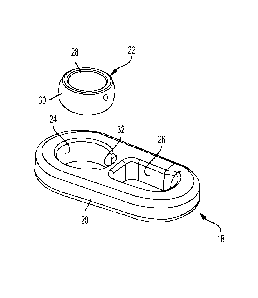
Referring to FIG. 2, an improved stud end link (or end link) 18 includes a
main
body 20, swivel ball bushing (or swivel ball) 22, truncated substantially
spherical mating
surface (or pass-through opening) 24 located at one end of the main body, and
link opening
(or pass-through opening) 26 located at the other end of the main body. The
main body 20
preferably has a generally oblong-like shape, with rounded corners and mildly
tapering
sides, but other shapes compatible with chain links or end links are suitable
as well. The
swivel ball 22 includes a pin bore 28 adapted to receive a matingly sized pin
(not shown)
or other cylindrical through-member, and a truncated substantially spherical
outer surface
(or wall) 30. The inner surface of the pin bore preferably is substantially
cylindrical. The
radius of the spherical outer surface 30 generally corresponds to the radius
of the spherical
mating surface 24 to provide a compatible fit. In reference to outer surface
30 and mating
surface 24, the term "truncated substantially spherical surface" is meant to
refer to a
surface that is generally curvilinear in two directions and generally
corresponds to a partial
surface portion of a sphere (such as a surface portion comprising a 360 degree
band around
an equator of the sphere). At one end of the mating surface 24 a channel or
slot 32 is
formed in the main body proximate to both a central region of the main body
and one end
of the link bore 26. The width of the slot is at least slightly greater than
the swivel ball's
thickness.
The link opening 26 preferably is an elongated opening with tapering sides
corresponding to the tapering sides of the main body 20. The link opening
serves to
receive and capture an adjacent chain link, as illustrated in FIG. 1.
The stud end link 18 (and main body 20) can be described with respect to a
coordinate axis system. While the end link (and main body) can have many
shapes, forms
and proportions, it preferably is longer than it is wide and has a thickness
that is less than
its length and width. Due to its preferably quasi-flat profile, the main body
20 can be said
- 4 -
CA 02936535 2016-12-23
to define a main body plane extending therethrough that bisects the main body
into upper
and lower halves. The main body plane is co-planar with the main body. A
longitudinal
center axis lying in the plane extends the length of the link and bisects the
main body into
two preferably generally symmetric or mirror image lateral halves. The
longitudinal center
axis also bisects the openings 24 and 26, preferably into two symmetric
halves. A lateral
axis perpendicular to the longitudinal center axis also lies in the plane and
passes through
the geometric center of the pass-through mating surface or opening 24. A
perpendicular
axis passes perpendicularly through the plane (defined by the longitudinal and
lateral axes)
and through the midpoint where the longitudinal and lateral axes intersect,
providing a 3-
axis coordinate system whose center is at the geometric center opening 24. A
lateral center
axis parallel to aforementioned center axis divides the main body laterally
into two
asymmetric halves.
Turning to FIG. 3, the swivel ball 22 is installed in the stud end link by
aligning the
swivel ball at a 90 degree (sideways) orientation to the main body 20,
inserting the swivel
ball into the spherical mating surface 24 and slot 32, moving the swivel ball
away from the
slot in a longitudinal direction and into contact with the mating surface 24,
and then
rotating the swivel ball about the longitudinal center axis.
FIG. 4 shows the swivel ball being partially rotated (about 45 degrees) within
the
mating surface 24.
FIG. 5 shows the swivel ball fully rotated (90 degrees) and seated within the
mating
surface 24 of the stud end link. As so seated, the spherical outer surface 30
of the swivel
ball and spherical mating surface 24 are in mating or nesting contact with one
another. As
the swivel ball is installed, the center axis of the pinhole 28 rotates 90
degrees from a
position substantially co-planar with the main body plane (and substantially
parallel to the
lateral axis) to a position perpendicular to the plane (and at least largely
coextensive with
the perpendicular axis).
Due to the geometry of the truncated spherical engaging surfaces, the swivel
ball is
captured by the main body 20 and largely restrained from moving relative to
the main
body, either longitudinally, laterally or perpendicularly, except to the
limited extent
- 5 -
CA 02936535 2016-07-18
described below. The swivel ball, which may also be referred to as a swivel
ball bushing,
is captured in place without any welding.
In operation, the stud end link is subject to large forces acting primarily in
the
direction of the longitudinal axis of the main body. The mating surface 24 of
the main
body provides a wall surface to support the lateral sides of the swivel ball
and, because the
mating surface engages the swivel ball largely on all sides, also supports the
longitudinal
sides of the swivel ball as well. The swivel ball as a whole also is prevented
from being
displaced perpendicularly (except in the limited pivoting manner described
below). In
other words, the swivel ball is constrained from translation movement in the
longitudinal,
lateral and perpendicular directions. (Any displacement perpendicularly "out
of plane" is
through pivoting movement.) Yet, the spherical surface interengagement of the
swivel ball
22 and mating surface 24 allows the main body to tilt or pivot a limited
amount "out of
plane" relative to the swivel ball as, for example, up to about 3 degrees off-
axis (including
up to about 1 degree and up to about 2 degrees off-axis) to accommodate off-
axis loads.
Depending on perspective it also can be said that the swivel ball is free to
swing or tilt "out
of plane" relative to the main body up to about 3 degrees off-axis (including
up to about 1
degree and up to about 2 degrees off-axis) to accommodate off-axis loads. Such
tilting
displacement occurs when the swivel ball pivots about the lateral axis (which
laterally
bisects the swivel ball pin hole 28) such that a distal end of the swivel ball
pivots out of
plane in one direction and the other proximal end (near the slot) pivots out
of plane in the
other direction.
At the same time, if the swivel ball becomes worn or otherwise needs to be
replaced, the swivel ball can be easily removed from the stud end link by
rotating the
swivel ball 90 degrees about the longitudinal center axis, shifting it in the
direction of the
slot 32, and moving it in a direction perpendicular to the plane of the main
body, thereby
reversing the installation process. As the swivel ball is not welded in place,
it is free to
rotate or spin within the main body plane about the perpendicular axis (i.e.,
relative to the
mating surface 24a).
The stud end link is used in coupling or attaching a variety of rigging
components
to one another, such as hitch extensions, spreader bars, upper/lower hoist
chains, drag rope
- 6 -
CA 02936535 2016-07-18
sockets, bucket hitches and the like. The stud end link generally would not be
used as a
regular intermediary link in a drag chain or other chain.
The main body 20 of the end link and swivel ball 22 may be made of a variety
of
materials suitable for chains and chain links used in draglines and heavy
equipment
environments including but not limited to high strength low alloy steel
(HSLA). As one
example, the swivel ball may be made of manganese steel. The dimensions of the
end link
and swivel ball may vary widely in the context of draglines and heavy
equipment, high
load use. By way of example, one embodiment of the swivel ball may have an
outer
diameter up to about 18 inches, an inner diameter (pin hole) up to about 12.25
inches and a
length up to about 46 inches.
It will be appreciated that the main body 20 and opening 26 can take many
different
forms and shapes in this embodiment and embodiments discussed later. For
example, in
some embodiments the body 26 can have converging or parallel sides. If the
sides
converge toward one another, the link opening 26 can be located on the wide
end or
narrow end of the main body 20, with the swivel ball 22 located on the other
end. The link
opening 26 preferably is rounded at its distal end and straight at its opposed
proximal end
(proximate the central area of the main body) as shown in FIGS. 3-5, but the
link opening
also can be rounded at both ends.
By way of further example, the main body typically as a length of about 10
inches
to about 46 inches (including about 12 to 38 inches), a width at its widest
point of about 3
to about 14 inches (including about 4 to 12 inches), and a thickness of about
1.5 inches to
about 9 inches (including about 3 to 7 inches).
By way of example, the pin bore 28 of the swivel ball typically has a diameter
of
about 2 inches to about 10 inches, such as about 3 to 8 inches. The thickness
of the swivel
ball typically is slightly greater than the thickness of the main body 20.
FIG. 6 illustrates how the stud end link may be coupled to a trunion 34 having
bracket legs 36a, 36b and corresponding bushings 38a, 38b seated therein. The
stud end
link 18 is coupled to the trunion 34 by moving the swivel ball 22 into
alignment with the
bushings 38a, 38h and locking the components in place by inserting a mating
pin 40
through the aligned bores of the bushings 38a, 38b and pin hole of the swivel
ball 22.
- 7 -
CA 02936535 2016-07-18
A second embodiment of the stud end link is shown in FIGS. 7-11. Referring to
FIG. 7, a stud end link 18a includes a main body 20a, swivel ball bushing or
swivel ball
22a, truncated substantially spherical mating surface (or opening) 24a, and
link opening
26a, as previously described. The general shape, form, material, dimensions
and other
characteristics of the stud link 18a correspond to the end link 18, except
where noted. For
example, the swivel ball 22a likewise has a pin bore 28a and truncated
substantially
spherical outer surface 30a. A channel or slot 32a also is provided on the
proximal side of
the mating surface 24a and centered on the longitudinal axis of the main body
28a, as
described previously.
Unlike the swivel ball 22, the swivel ball 22a is provided with a locking tab
42 on
the slot side of the spherical outer surface 30a. The tab 42 aligns with the
slot 32a and
preferably is bisected by the longitudinal axis of the main body. The tab 42
preferably is
symmetric relative to the longitudinal axis (as is mating surface 24a). As
shown in the
longitudinal cross section views of FIGS. 8, 9, however, the tab 42 preferably
is not
symmetric in the perpendicular direction. In other words, the tab is not
symmetric relative
to the main body plane. The thickness of the tab tapers and becomes thinner
moving
perpendicularly from one surface (e.g., top surface) of the main body to the
other surface
(e.g., lower surface). The outer surface of the tab 42 is curvilinear in two
directions to
form a truncated substantially spherical surface. Similarly, the slot 32a
presents a reverse
mirror image, and has a truncated substantially spherical surface that mates
or nests with
the locking tab 42. Thus, the slot 32 is symmetric relative to the
longitudinal axis but
asymmetric relative to the perpendicular axis.
As FIGS. 7, 8 and 9 illustrate, the slot 32a is curvilinear in the
perpendicular and
lateral directions and has a taper. Unlike the tab 42, however, the thickness
of the slot wall
is thinnest at the top surface of the main body and gets thicker moving toward
the bottom
surface, thereby providing a mating fit with the tab 42. Put another way, the
depth of the
slot is greatest at the top surface and smallest at the bottom surface. The
mating truncated
spherical geometries of the tab and slot, as well as the mating geometries of
the rest of the
swivel ball's outer surface 30 and mating surface 24a, allow the swivel ball
to tilt or pivot
relative to the main body outside the plane of the main body, as explained
further below.
- 8 -
CA 02936535 2016-07-18
Yet, the swivel ball is constrained by the locking tab from rotating or
spinning within the
mating surface 24a (i.e., within the plane of the main body), unlike the
embodiment
described above.
Stated differently, the swivel ball and main body have several paths of
possible
relative movement. Within the plane of the main body, the swivel ball (once
installed) is
absolutely constrained from translation movement both longitudinally or
laterally, and
from spinning or rotating about a perpendicular axis of rotation passing
through the center
of the swivel ball's pin bore 28a. The swivel ball, however, can tilt or pivot
a limited
amount about a lateral pivot axis passing through the midpoint of the swivel
ball's pin
hole, as described above. And the swivel ball can pivot or rotate at least 90
degrees about
a longitudinal axis passing through the center of the swivel ball (as well as
the tab) to
facilitate installation and removal of the swivel ball.
Referring to FIG. 10, the swivel ball 22a preferably is eccentric for a second
reason
other than the tab's location at one end. The wall thickness of the swivel
ball at the distal
end is thicker and tapers as it approaches the tab 42. In other words, the
wall thickness of
the swivel ball is thinnest in the areas on either side of the tab 42 and
thickest at the
opposite distal, longitudinally-opposed end.
Explained in a different way (and ignoring the tab 42 for illustration), the
additional
material on the distal end of the swivel ball is created by shifting the
swivel ball's bore (or
pin hole) a certain distance, preferably about 1/4 inch to 3/4 inch, in the
direction of the
slot, such that the swivel ball is slightly eccentric. In other words, the
center axis defined
by the cylindrical pinhole 28a is displaced about 1/4 inch to 3/4 inch
relative to the center
axis of the outer surface 30a. The pinhole 28a and outer surface 30a have
center axes that
are displaced and not coincident.
Most of the force exerted on the stud end link by the dragline is applied in
the pull
direction of arrow F shown in FIG.10, and results in substantial loading and
maximum
wear on the longitudinal distal side of the swivel ball 22a. The eccentric
swivel ball, with
additional material on the high wear side of the swivel ball, facilitates
additional service
life during operation.
- 9 -
CA 02936535 2016-12-23
Referring to FIG. 11, the main body 20a of the end stud link is shown attached
to a
trunion 34a having a mating pin 40a and bracket legs 44a, 44b, each of which
seats a
bushing. The end stud link is located between the bracket legs 44a, 44b and
captured in
place by the mating pin 40a, which extends through the pin bore 28a of the
swivel ball 22a.
Due to the truncated spherical connection between the swivel ball 22a and main
body 20a,
the main body is able to pivot or swing in the perpendicular direction a
distance, preferably
up to about 1-1/2 degrees on each side of vertical, for a total pivot angle or
swing angle A
of up to about 3 degrees (including up to about 2 degrees and up to about 1
degree).
Notably, the pin 40a and swivel ball 22a mounted thereto remain fixed, and the
main body
20a of the end chain link pivots or swings relative thereto to accommodate off
axis
loading.
FIG. 12 is a perspective view of a conventional dragline bucket 46, pair of
dragline
chains 48, pair of lower hoist chains 50, spreader bar 52, pair of upper hoist
chains 54,
hoist rope rigging 56, and pair of dump chains 58, which are interconnected to
form a
dragline. The disclosed end chain link is well suited for connecting chains to
various
rigging components as, for example, connecting dump chains to drag chains,
drag chains to
the bucket, upper and lower hoist chains to the spreader bar, and upper hoist
chains to the
hoist rope rigging.
FIG. 13 is a perspective view of a third embodiment comprising a swivel link
60
having a main body 62, a pair of openings or mating surfaces 64a, 64b at
opposite ends of
the main body, each having respective slots as described above, and pair of
swivel balls
66a, 66b seated in respective openings 64a, 64b. The swivel balls 66a, 66b
have respective
pin holes 68a, 68b and tabs 70a, 70b as described above. The pin holes receive
respective
pins or cross-members for coupling the swivel link to other rigging
components.
The swivel balls 66a, 66b and mating surfaces 64a, 64b having mating truncated
substantially spherical geometries to allow the pivoting movement discussed
above to
accommodate off-axis loads. The tabs and slots likewise have similar mating
truncated
substantially spherical surfaces as described above to permit select pivoting
movement of
the main body and each swivel ball relative to one another, while preventing
relative
- 10 -
CA 02936535 2016-12-23
translation movement therebetween as well as rotation or spinning movement of
the swivel
balls within the openings.
Unlike main body 20, 20a, the main body 62 has enlarged ends and a tapered
waist.
Also, the main body 62 seats two swivel balls in openings that are
perpendicular to one
another.
In using the terms "end link" and "stud end link" herein, such terms are
intended to
encompass swivel links as shown in FIG. 13, hoist links, sockets and like
components.
In view of the many possible embodiments to which the principles of the
disclosed
invention may be applied, it should be recognized that the illustrated
embodiments are only
preferred examples of the invention and should not be taken as limiting the
scope of the
invention. Rather, the scope of the invention is defined by the following
claims.
- 11 -