Note: Descriptions are shown in the official language in which they were submitted.
CA 02936545 2016-07-19
DRY ADHESIVE BACKED FLOORING AND METHOD FOR MANUFACTURE
[0001] This application is a division of Canadian application number 2,
703,424 filed on
May 7, 2010.
FIELD
[0002] This disclosure relates to the field of vinyl and other sheet flooring
provided in
rolls. More particularly, this disclosure relates to sheet flooring having pre-
applied dry
adhesive and to the manufacture thereof.
BACKGROUND
[0003] Currently, most vinyl, rubber and other sheet flooring products are
installed to a
subfloor with wet adhesives. The wet adhesives are applied to the subfloor as
by use of a
notched trowel. The applied adhesives are allowed to cure for a prescribed
amount of
time, after which the flooring material typically provided as a large roll is
laid and then
rolled with a weighted roller. This method can be time consuming, messy and
with high
moisture or high pH concrete subfloors, lead to adhesive failure. In addition,
the
adhesives typically have volatile organic compounds. Thus, especially when
applied in a
hospital setting, the area must typically be evacuated for several days and
measures taken
to avoid exposure of adjacent areas to the volatiles.
[0004] In addition, especially in the hospital setting in which the floor is
exposed to
regular movement of a heavy bed on rollers, conventional wet adhesive applied
floorings
tend to disadvantageously creep, buckle, and otherwise deform after relatively
short
periods of time. In addition, the flooring industry has been having problems
with regular
processed glue adhesive in high moisture areas. Various mitigation methods
have been
attempted, but such methods are typically of high cost and generally
unsatisfactory
results.
[0005] Accordingly, improvement is desired in the field of sheet flooring, and
in the
installation of the same, especially in hospital settings and in high moisture
areas, such as
coastal areas and areas having relatively high humidity levels.
CA 02936545 2016-07-19
[0006] The present disclosure advantageously enables the provision of rolled
flooring
having a sheet flooring material married to a double-sided sheet adhesive in
such a
manner that the resulting flooring material is substantially free of bubbles
and wrinkles
that would show through when the flooring material is installed on the
subfloor. The
disclosure also provides methods and apparatus for manufacture of the
flooring, and
methods for installation of the flooring.
SUMMARY
[0007] The above and other needs are met by a dry adhesive backed flooring for
being
installed in a flat orientation on a subfloor.
[0008] In accordance with an aspect of the invention there is provided a
method of
manufacturing a dry adhesive backed flooring for being installed in a flat
orientation on a
subfloor, the method comprising the steps of: providing a roll of a sheet
flooring material
provided in a roll, the sheet flooring material having a first length, a first
width, a decorative
upper surface, and an opposite under surface; providing a roll of a double-
sided dry sheet
adhesive substantially free of volatile organic compounds, the sheet adhesive
having a
second length substantially corresponding to the first length, a second width
slightly less
than but substantially corresponding to the first width, and first and second
adhesive
surfaces, and contacting the first adhesive surface to the under surface of
the sheet
flooring material to marry the sheet flooring material and the sheet adhesive
to yield the
dry adhesive backed flooring, wherein the dry adhesive backed flooring is
installable on a
subfloor by contacting the second adhesive surface to the subfloor, to yield
an installed dry
adhesive backed flooring that is substantially free of bubbles and wrinkles
and the second
adhesive surface of the sheet adhesive will substantially permanently maintain
the installed dry
adhesive backed flooring adhered to the subfloor such that the installed dry
adhesive backed
flooring will remain substantially flat as initially installed and not
significantly rise from the
subfloor, bubble or otherwise detach from the subfloor under normal use
conditions for the dry
adhesive backed flooring.
[0009] In accordance with another aspect of the invention there is provided a
method of
manufacturing dry adhesive backed flooring for being installed in a flat
orientation on a
2
CA 02936545 2016-07-19
subfloor, the method comprising the steps of: providing a continuous sheet
vinyl or rubber
flooring material having a first length, a first width, a decorative
continuous upper surface, and
an opposite continuous under surface; and providing a continuous double-sided
dry sheet
adhesive having a second length substantially corresponding to the first
length, a second
width slightly less than but substantially corresponding to the first width,
and first and
second adhesive surfaces, contacting the first adhesive surface as a dry sheet
to the under
surface of the sheet flooring material to marry the double-sided dry sheet
adhesive to the
sheet flooring material; wherein the dry adhesive backed flooring is
installable on a subfloor
by contacting the second adhesive surface to the subfloor, to yield an
installed dry adhesive
backed flooring that is substantially free of bubbles and wrinkles and the
second adhesive
surface of the sheet adhesive will substantially permanently maintain the dry
adhesive backed
flooring adhered to the subfloor such that the installed dry adhesive backed
flooring will
remain substantially flat as initially installed and not significantly rise
from the subfloor,
bubble or otherwise detach from the subfloor under normal use conditions for
the dry
adhesive backed flooring.
[0010] In accordance with yet another aspect of the invention there is
provided a dry
adhesive backed flooring for being installed in a flat orientation on a
subfloor, the
flooring, comprising: a sheet flooring material having a first length, a first
width, a
decorative upper surface, and an opposite under surface; and a double-sided
dry sheet
adhesive married to the sheet flooring material, the sheet adhesive being
substantially
free of volatile organic compounds and having a second length substantially
corresponding to the first length, a second width slightly less than but
substantially
corresponding to the first width, and first and second dry adhesive surfaces,
the first dry
adhesive surface being adhesively secured as a dry surface to the under
surface of the
sheet flooring material to marry the double-sided dry sheet adhesive to the
sheet flooring
material to yield a dry adhesive backed flooring; wherein the dry adhesive
backed flooring
is installable on a subfloor by contacting the second dry adhesive surface to
the subfloor to
yield an installed dry adhesive backed flooring that is substantially free of
bubbles and
wrinkles and the second dry adhesive surface of the sheet adhesive will
substantially
permanently maintain the installed dry adhesive backed flooring adhered to the
subfloor
such that the installed dry adhesive backed flooring will remain substantially
flat as initially
3
CA 02936545 2016-07-19
installed and not significantly rise from the subfloor, bubble or otherwise
detach from the
subfloor under normal use conditions for the dry adhesive backed flooring.
[0011] In accordance with still yet another aspect of the invention there is
provided a dry
adhesive backed flooring for being installed in a flat orientation on a
subfloor, the
flooring comprising: a continuous sheet vinyl or rubber flooring material
having a first
length, a first width, a decorative continuous upper surface, and an opposite
continuous
under surface; and a continuous double-sided dry sheet adhesive having a
second length
substantially corresponding to the first length, a second width slightly less
than but
substantially corresponding to the first width, and first and second dry
adhesive surfaces,
the first dry adhesive surface being adhesively secured as a dry surface to
the under
surface of the sheet flooring material to marry the double-sided dry sheet
adhesive to the
sheet flooring material; wherein the dry adhesive backed flooring is
installable on a
subfloor by contacting the second dry adhesive surface to the subfloor to
yield an installed
dry adhesive backed flooring that is substantially free of bubbles and
wrinkles and the
second dry adhesive surface of the sheet adhesive will substantially
permanently maintain
the installed dry adhesive backed flooring adhered to the subfloor such that
the installed dry
adhesive backed flooring will remain substantially flat as initially installed
and not
significantly rise from the subfloor, bubble or otherwise detach from the
subfloor under
normal use conditions for the dry adhesive backed flooring.
[0012] In accordance with still yet another aspect of the invention there is
provided a dry
adhesive backed flooring for being installed in a flat orientation on a
subfloor, the
flooring, comprising: a continuous sheet flooring material having a first
length, a first
width, a continuous decorative upper surface, and an opposite continuous under
surface; a
continuous double-sided dry sheet adhesive having a second length
substantially
corresponding to the first length, a second width slightly less than but
substantially
corresponding to the first width, and first and second dry adhesive surfaces,
the first dry
adhesive surface being adhesively secured as a dry surface to the under
surface of the
sheet flooring material to marry the double-sided dry sheet adhesive to the
sheet flooring
material; and a release liner removably secured to the second dry adhesive
surface;
wherein the dry adhesive backed flooring is installable on a subfloor by
contacting the
4
CA 02936545 2016-07-19
second dry adhesive surface to the subfloor to yield an installed dry adhesive
backed
flooring that is substantially free of bubbles and wrinkles and the second dry
adhesive
surface of the sheet adhesive will substantially permanently maintain the
installed dry
adhesive backed flooring adhered to the subfloor such that the installed dry
adhesive
backed flooring will remain substantially flat as initially applied installed
and not
significantly rise from the subfloor, bubble or otherwise detach from the
subfloor under
normal use conditions for the dry adhesive backed flooring.
BRIEF DESCRIPTION OF THE DRAWINGS
[0013] Further advantages of the disclosure are apparent by reference to the
detailed
description when considered in conjunction with the figures, which are not to
scale so as
to more clearly show the details, wherein like reference numbers indicate like
elements
throughout the several views, and wherein:
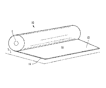
[0014] FIG. 1 is a perspective view of a roll of dry adhesive backed flooring
according to
the disclosure.
[0015] FIG. 2 is an exploded perspective view of a section of the flooring of
FIG. 1.
[0016] FIG. 3 is a side view of apparatus according to the disclosure for
manufacturing
the flooring of FIG. 1, and FIG. 4 is a top plan view of the apparatus of FIG.
3.
[0017] FIG. 5 is a side view of an alternate apparatus according to the
disclosure for
manufacturing the flooring of FIG. 1
CA 02936545 2016-07-19
DETAILED DESCRIPTION
[0018] With reference to the drawings, the disclosure relates to a dry
adhesive backed
flooring 10 that may be readily applied to a subfloor S, such as a concrete
slab common
to hospital floor structures, and to apparatus and methods for manufacturing
and
installing the flooring 10. The flooring 10 is provided as a roll on a core C
and includes a
sheet flooring material 12 married to a double-sided sheet adhesive 14. As
described
more fully below, the sheet material 12 and the sheet adhesive 14 are married
in such a
manner that the resulting flooring material 10 is substantially free of
bubbles and
wrinkles that would show through when the flooring material 10 is installed on
the
subfloor S.
[0019] The sheet flooring material 12 is a vinyl, rubber, or other sheet
flooring product
provided as a roll 16 (FIG. 3) It will be appreciated that the sheet material
12, and hence
the flooring 10, may be provided in virtually any width, thickness, and length
common to
rolled sheet flooring. However, especially for hospital applications, the
sheet material 12
is provided in widths of from about 4 to about 7 feet and in lengths of up to
about 100
feet. The sheet flooring material 12 has an upper decorative surface 18
opposite an
underside surface 20. Conventionally, the underside surface 20 is somewhat
roughened
for better suitability with wet adhesives, such as latex adhesives,
conventionally used to
apply sheet flooring to a subfloor. It has been observed that the sheet
material 12 for use
in accordance with the disclosure may have the underside surface 20 roughened,
as is
conventional, or the underside surface 20 may be smooth.
[0020] The double-sided sheet adhesive 14 is provided as a roll (Fig. 3) and
includes a
scrim 22 having opposite adhesive surfaces 24 and 26. The sheet adhesive 14 is
provided
on a roll having a length at least the length of the roll of the flooring
material 12 to which
it is to be applied. The lower adhesive surface 26 is covered by a release
liner 28.
Accordingly, when in its roll form, the adhesive 14 is rolled so that the
release liner 28
provides the outermost surface of the roll and the adhesive surface 24 faces
the release
liner 28. A preferred double-sided sheet adhesive is a double-sided
polyacrylic adhesive
sheet material having a polyethylene terephthalate (PETP) scrim coated on both
sides
with a thin and uniform layer of a polyacrylic-based transfer adhesive and
covered on one
6
CA 02936545 2016-07-19
side by a silicon coated paper release liner. The scrim 22 has a thickness of
about 130
microns (5.12 mils) and the adhesive surfaces are applied in an amount of
about 0.0029
to about 0.0053 ounces per square inch.
[0021] The width of the roll of the sheet adhesive 14 substantially
corresponds to the
width of the roll of the flooring material 12, preferably being slightly less
such that the
adhesive 14 does not extend beyond the side edges of the flooring material 12.
For
example, for a roll of the flooring material 12 having a width of 6 feet (70
inches), the
sheet adhesive 14 preferably has a width of about 69.5 inches, with the sheet
adhesive 14
centered relative to the flooring material 12 to leave a space of about 0.25
inches between
the edge of the sheet adhesive 14 and the edge of the flooring material 12.
[0022] It has unexpectedly been discovered that application of a scrim
reinforced
polyacrylic adhesive to vinyl or rubber flooring products according to the
disclosure
yields a bond between the sheet adhesive and the flooring and a bond between
the
subfloor and the sheet adhesive that substantially permanently maintains the
flooring
adhered to the subfloor, even when subjected to wet conditions. In this
regard, the
terminology "substantially permanently maintains" will be understood to mean
that the
flooring remains substantially flat as initially applied and does not
significantly rise from
the subfloor, bubble or otherwise detach from the subfloor under normal use
conditions
for the flooring. Normal use conditions means use conditions of the flooring
common to
the environment, such as rolling a bed thereon, walking upon, and the like, as
to be
distinguished from acts specifically designed to remove flooring, such as
pulling
upwardly thereon with substantial force. In addition, it has been unexpectedly
observed
that the flooring 10 may in fact be applied to a wet concrete subfloor and
that the sheet
adhesive 14 thereof substantially permanently maintains the flooring adjacent
the
subfloor. Accordingly, the flooring 10 has been observed to be particularly
suitable for
application in environments that experience wet conditions, such as in
basements, wash
rooms and the like.
[0023] Without being bound by theory, it is believed that the scrim reinforced
polyacrylic
sheet adhesive 14 creates a barrier that resists water in the concrete
subfloor S from
7
CA 02936545 2016-07-19
penetrating therethrough, and it has been observed that the scrim reinforced
polyacrylic
sheet adhesive 14 substantially inhibits drawing or wicking of water. It is
further
believed that use of the sheet adhesive 14 to bond vinyl and rubber flooring
or the like to
concrete or other subfloor materials requires two bonds: one to the underside
of the
flooring material and one to the subfloor. In this regard, manufacture of the
flooring 10
as described herein allows for the bond of the adhesive to the flooring
material to take
place in a controlled environment and in a precise manner that avoids the
formation of
bubbles and wrinkles in the flooring material 10 that would show through when
the
flooring 10 is installed on the subfloor S.
100241 In brief overview of the manufacture of the flooring 10, it has been
discovered
that marriage of the flooring material 12 and the sheet adhesive 14 in roll
form requires
attention to several key factors. For example, it has been observed that it is
very difficult
to marry the flooring material 12 and the sheet adhesive 14 while avoiding
bubbles and
wrinkles that would show through when applied or installed on the flooring 10.
Vinyl
and rubber sheet flooring products come from several different manufactures
with
varying compositions and widths, all of which become factors in successful
application.
With some materials temperature during application can also be a factor.
Certain
materials require to be rolled surface face out and others face in.
[0025] For example, for softer compositions, width guides provided on the
apparatus for
the flooring material are pinched in until the material is slightly bowed
(crimped between
the guides until it rises off the table). It has been discovered that this is
advantageous so
that when the tension from the winding application is in effect, the material
shrinks to fit
in the guides. With regard to temperature, the ambient temperature typically
changes the
flexibility of the flooring material 12. Cold makes the material stiffer, and
warmer
weather makes the material more pliable and slower processing speeds may be
indicated
for the colder materials. However, it is desirable to provide a manufacturing
environment
having a substantially uniform temperature year-round to minimize any
temperature
related effects. With regard to orientation, it is desirable to use of
flooring materials with
a relatively soft wear layer face out. Everything else is typically wound face
in. Softness
may be determined by depressing a thumbnail or small blunt tool into the
surface of the
8
CA 02936545 2016-07-19
material. If it leaves and indentation that does not go away in a few seconds,
it is
considered soft and is rolled face out to protect the material.
[0026] It has been discovered that a preferred point to accomplish marriage of
the sheet
adhesive 14 to the flooring material 12 is right as it is being rolled up onto
the core C to
result in the flooring 10 being substantially free of bubbles and wrinkles
that would show
through when the flooring material 10 is installed on the subfloor S. In
addition, the
flooring material 12 and the sheet adhesive 14 must be maintained at a desired
angle so
they consistently meet right at the marriage point. Also, having the sheet
material 14 in a
desired thickness and width is necessary to provide proper coverage to the
edges without
allowing bleedthrough at the seams of the flooring during installation. Also,
substantially
even tension must be applied to the roll of the sheet adhesive as it unwinds
to keep it
running straight and wrinkle-free.
[0027] With reference now to Figs. 3 and 4, there is shown a schematic of an
apparatus
30 configured to desirably marry the sheet adhesive 14 with the flooring
material 12 to
yield the flooring 10 so that it is substantially free of bubbles and wrinkles
that would
show through when the flooring material 10 is installed on the subfloor S.
[0028] The marriage apparatus 30 includes a frame 32 onto which is located a
flooring
material support 34, a table 36, a flooring material position indicator 38, a
sheet adhesive
support 40, a sheet adhesive tensioning system 42, a flooring support 44, and
a weight
system 46 for bearing against the flooring support 44. The apparatus 30 may
further
include a weighted roller 48 and a lateral adjustment roller 50.
[0029] The apparatus 30 is configured to provide the flooring 10 in a rolled
orientation
with the decorative surface 18 facing inward. This is desirable to protect the
decorative
surface 18. However, as described below in connection with FIG. 5, apparatus
may be
configured to provide the flooring 10 in a rolled orientation with the
decorative surface
18 facing outward.
[0030] The frame 32 provides a sturdy support for mounting and positioning the
various
components of the apparatus 30, and may be provided as by welded steel
construction.
9
CA 02936545 2016-07-19
The flooring material support 34 is located at a first end of the frame 32 and
includes a
pair of support rollers 52 onto which the roll 16 of the sheet flooring
material 12 is
placed, with the material 12 unrolling from the bottom of the roll 16 with the
roll 16
rotating counterclockwise on the support rollers 52. The support rollers 52
are mounted
on a lateral positioning system 54 that is movable laterally, e.g., left or
right, relative to
the frame 32 and the table 36 on the frame 32. Movement of the lateral
positioning
system 54 is controlled as by a computer controller 56 associated with the
positioning
system 54 in response to feedback from the flooring material position
indicator 38. The
controller 56 may communicate with the positioning system 54 and the position
indicator
38 as by wire or wireless interface. The lateral positioning system 54 may be
provided as
by an electrically powered wheeled member 54a laterally movable on a track 54b
as by
an electric drive motor controlled by the computer controller 56.
100311 The table 34 provides a large flat surface across which the flooring
material 12 is
extended to enable the width of the flooring material 12 to be aligned with
the sheet
adhesive 14. In this regard, the table 34 includes a flat surface 60 along the
longitudinal
sides is disposed a pair of width guides 62. The table 34 includes a roller 64
located at
the distal end of the table 34 so as to enable the flooring material 12 to be
directed from
the table 34 to the flooring support 44 at a desired angle. In this regard, as
explained
below, it has been discovered that a desired angle of the flooring material 12
relative to
the sheet adhesive 14 is desired to enable satisfactory marriage of the
flooring material 12
and the sheet adhesive 14 to provide the flooring 10. The weighted roller 48
may be
provided above the table 30 if desired to be positioned to bear against the
flooring
material 12 if needed to maintain tension in the material 12, such as when the
material 12
is substantially at the end of the roll.
100321 The flooring material position indicator 38 may be provided as by an
electrical
eye or other sensor suitable for detecting the location of the edge of the
flooring material
12 relative to one of the guides 62 and for providing corresponding signals to
the
computer controller 56 for comparing the location of the edge of the flooring
material 12
to a predetermined threshold. If the location of the edge of the flooring
material 12
exceeds the threshold, information in this regard from the indicator 38 is
utilized by the
0
CA 02936545 2016-07-19
computer controller 56 to generate a signal to the lateral positioning system
54 that
results in the positioning system 54 adjusting the position of the flooring
material 14 so
that the edge thereof is returned to a location within the predetermined
threshold. For
example, the wheeled member 54a will move along the track 54a in a desired
direction
and a desired amount to reposition the support rollers 52, and hence the roll
16 of the
flooring material 14, a desired amount. The position indicator 38 preferably
updates the
location information substantially continuously.
[0033] The lateral adjustment roller 50 may also be utilized in conjunction
with the
position indicator 38 to adjust the location of the edge of the flooring
material 12. For
example, the roller 50 is located adjacent the distal end of the table 32 and
may be
configured to enable application of non-uniform pressure onto the material 12
to urge the
material so that it moves laterally one way or the other. The roller 50 may be
computer
controlled utilizing information from the position indicator 38 in the manner
of the
positioning system 54.
[0034] The sheet adhesive support 40 is provided as by an air expandable
bladder shaft
66 configured to rotatably receive and to expand to snugly engage the roll of
the sheet
adhesive material 14 as it unrolls. The sheet adhesive support 40 is located
downline
from the flooring material support 34, and upline from the flooring support
44. The sheet
adhesive tensioning system 42 is provided as by a pair of laterally spaced
bars 68 over
which the sheet adhesive 14 is passed. The bars 68 are independently and
vertically
adjustable relative to the support 40 and are adjusted to positions to
maintain a
substantially uniform and desired tension on the sheet adhesive 14 as it is
unrolled during
the manufacture of the flooring 10.
[0035] The flooring support 44 is provided as by a power driven and air
expandable
bladder shaft 70 configured to rotatably receive and to expand to snugly
engage the core
C onto which the flooring represented by the married flooring material sheet
12 and the
sheet adhesive 14, is rolled to provide the finished flooring material 10. The
flooring
support 44 is located downline of the sheet adhesive support 40. The shaft 70
may be
rotated at a desired speed as by an electrical motor.
11
CA 02936545 2016-07-19
[0036] The weight system 46 is configured to bear against the outer surface of
the
enlarging roll of the flooring 10 as the flooring 10 is manufactured. This is
desirable to
maintain a desirably tight winding of the roll of the flooring 10. The weight
system 46
may include a steel bar 72 pivotally mounted to the frame 32 adjacent the
roller 64 and
having a roller 74 located at a distal end thereof for engaging the roll of
the flooring 10.
[0037] As shown in FIG. 3, the apparatus 30 is configured so that the flooring
material
12 unrolls from the roll 16 and onto the table 32 to a substantially flat
orientation,
extending in this manner to the roller 64. The flooring material 12 curves
over the roller
64 and downward to the core C mounted on the shaft 70 of the flooring support
44. The
sheet adhesive 14 unrolls from a location in-between the roll 16 and the core
c, and
passes over the sheet adhesive tensioning system 42 and to the core C. In this
regard, it
has been observed to be beneficial to maintaining tension of the sheet
adhesive 14 to
maintain the angle of the sheet 14 approaching the tensioning system 42 at an
angle A of
from about 30 to about 60 degrees, and maintaining the angle between the
leading and the
trailing one of the rollers 62 at an angle B of from about 0 to about -20
degrees.
[0038] The confluence of the flooring material 12 and the sheet adhesive 14 at
the core C
provides a marriage point MP of the flooring material 12 and the sheet
adhesive 14. The
marriage point MP is defined substantially at the core C, it being understood
that the
marriage point MP, while initially at the core C, will radially migrate from
the core C
corresponding to the thickness of the roll of the flooring 10 as the roll of
the flooring 10
enlarges. In this regard, it has been observed that it is advantageous to
maintain the angle
between the flooring material 12 and the sheet adhesive 14 approaching the
marriage
point MP at an angle C of from about 65 degrees to about 85 degrees, most
preferably
about 78 degrees.
[0039] In operation of the apparatus 30 to marry the flooring material 12 and
the sheet
adhesive 14 to provide the flooring 10, the flooring material 12 and the sheet
adhesive 14
are each located on the apparatus 30 as described and initially each secured
to the core C
located on the powered shaft as by tape or the like. Then, the powered shaft
70 is rotated
at a desired rotational speed, initially of about 4 rpm, ramping up to about
25 rpm, until
12
. CA 02936545 2016-07-19
,
. .
the end of the roll of the flooring material 12 is approached, at which time
the speed is
slowed. As will be appreciated, the powered shaft 70 serves to appropriately
unwind the
rolls of the flooring material 12 and the sheet adhesive 14, with the flooring
material
support 34 and the flooring material position indicator 38 operating as
described to
maintain the flooring material 12 in alignment with the sheet adhesive 14, and
the sheet
adhesive tensioning system 42 maintaining desired tension of the sheet
adhesive 14. In
this manner, the apparatus 30 functions to marry the flooring material 12 and
the sheet
adhesive 14 (with the underside surface 20 married to the adhesive surface 24)
in such a
manner that the resulting flooring material 10 is substantially free of
bubbles and
wrinkles that would show through when the flooring material 10 is installed on
the
subfloor S.
[0040] With reference now to FIG. 5, there is shown an apparatus 80 configured
for use
with the flooring material 12, when it is of a type with a relatively soft
wear layer face
out, and configured to roll the material 12 face out to protect the material.
The apparatus
80 may include the same components as the apparatus 30, such components
bearing the
same reference numerals as in the apparatus 30, except an additional component
in the
nature of a nip 82 provided by opposed rollers 84 and 86. In this regard, the
nip 82
provides a location for a new marriage point MP', the new location being
remote from
the core C and closer to the roll of the sheet adhesive 14. It has been
observed that a
slight decrease of the angle at which the flooring material 12 and the sheet
adhesive 14
meet at the new marriage point MP', with an angle C' of from about 60 degrees
to about
80 degrees, most preferably about 70 degrees. The apparatus 80 may be operated
in
substantially the same manner as the apparatus 30 to provide the flooring 10
which is
substantially free of bubbles and wrinkles that would show through when the
flooring
material 10 is installed on the subfloor S.
[0041] The flooring 10 according to the disclosure is substantially easier and
less time
consuming to install as compared to conventional wet adhesive applied rolled
flooring.
For example, the flooring 10 may be applied as by simply unrolling the
flooring 10 over
the subfloor S, while removing the release liner 28 so that the adhesive
surface 26 faces
and overlies the subfloor S. Next, a heavy roller or the like is rolled over
the thus
13
CA 02936545 2016-07-19
installed flooring 10, rendering the flooring 10 in an installed state, with
the flooring 10
being immediately available for use, including heavy foot traffic, rolling of
a bed or the
like, with no further treatment or curing of the adhesive being needed. The
subfloor S
may even be wet without negatively impacting installation, however, it is
preferred that it
not have an appreciable dirt, dust, or other loose particulate matter thereon.
[0042] Another advantage of the flooring 10 is that the sheet adhesive 14 is
substantially
free of any volatile organic compounds or the like, such that the area into
which the
flooring 10 is installed may be immediately occupied. In addition, it has been
observed
that the flooring 10 has greatly enhanced resistance to bubbling, rising, or
the like as is
common to conventionally adhered flooring, and due to this, is able to last
substantially
longer, especially in the hospital environment, where the floor is often
exposed to
moisture and heavy use as by the rolling of beds thereon. In this regard, the
flooring 10
once applied is substantially permanently maintained adjacent the subfloor by
the sheet
adhesive 14 while avoiding bubbling, rising, and the like. In addition, the
installed
flooring 10 has an aesthetically pleasing appearance, and is substantially
free of bubbles
and wrinkles.
[0043] The foregoing description of preferred embodiments for this disclosure
has been
presented for purposes of illustration and description. It is not intended to
be exhaustive
or to limit the disclosure to the precise form disclosed. Obvious
modifications or
variations are possible in light of the above teachings. The embodiments are
chosen and
described in an effort to provide the best illustrations of the principles of
the disclosure
and its practical application, and to thereby enable one of ordinary skill in
the art to
utilize the disclosure in various embodiments and with various modifications
as are suited
to the particular use contemplated. All such modifications and variations are
within the
scope of the disclosure as determined by the appended claims when interpreted
in
accordance with the breadth to which they are fairly, legally, and equitably
entitled.
14