Some of the information on this Web page has been provided by external sources. The Government of Canada is not responsible for the accuracy, reliability or currency of the information supplied by external sources. Users wishing to rely upon this information should consult directly with the source of the information. Content provided by external sources is not subject to official languages, privacy and accessibility requirements.
Any discrepancies in the text and image of the Claims and Abstract are due to differing posting times. Text of the Claims and Abstract are posted:
| (12) Patent: | (11) CA 2936911 |
|---|---|
| (54) English Title: | DOWNHOLE TRACTOR WITH REDUNDANT MOTOR DRIVES WITH INDEPENDENT CIRCUIT BREAKERS |
| (54) French Title: | TRACTEUR DE FOND DE TROU A MOTEURS D'ENTRAINEMENT REDONDANTS POURVUS DE DISJONCTEURS INDEPENDANTS |
| Status: | Granted and Issued |
| (51) International Patent Classification (IPC): |
|
|---|---|
| (72) Inventors : |
|
| (73) Owners : |
|
| (71) Applicants : |
|
| (74) Agent: | SMART & BIGGAR LP |
| (74) Associate agent: | |
| (45) Issued: | 2021-05-11 |
| (86) PCT Filing Date: | 2014-01-28 |
| (87) Open to Public Inspection: | 2015-08-06 |
| Examination requested: | 2019-01-04 |
| Availability of licence: | N/A |
| Dedicated to the Public: | N/A |
| (25) Language of filing: | English |
| Patent Cooperation Treaty (PCT): | Yes |
|---|---|
| (86) PCT Filing Number: | PCT/NO2014/000006 |
| (87) International Publication Number: | WO 2015115904 |
| (85) National Entry: | 2016-07-14 |
| (30) Application Priority Data: | None |
|---|
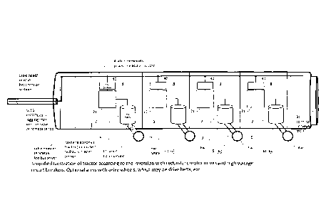
The invention is a downhole petroleum well tractor having a main body (0) connectable to an electrical conductor logging cable (5) from a surface high voltage DC power supply (50), characterized by said main body (0) comprising a common HV DC power line (4) provided with high-voltage DC power supplied from said electrical cable (5); two or more HV DC branch power lines (40) from said common HV DC power line (4), each said HV DC branch power line (40) feeding power to a HV motor drive electronic unit (21) for a drive motor (2); each said drive motors (2) driving one or more drive devices (6) for running on and along a wall in a well for moving said tractor; separate HV DC circuit breaker units (8) on each said HV DC branch power line (40), each said HVDC circuit breaker (8) unit comprising control means (82, 86, 88) arranged for monitoring a current (I) on said HV DC branch power line (40) and controlling a HV DC power switch (84) on said HV DC branch power line (40) to break said current (I) if said current (I) exceeds said set current level (Imax). Each said HV circuit breaker unit (8) is arranged to disconnect its associated motor (2) in case of said associated motor (2) fails, by detecting an increased current above a set current level, in order to prevent shorting said HV power line (4), thus maintaining operation of the other motors (2) of the tractor.
L'invention concerne un tracteur de puits de pétrole de fond de trou comprenant un corps principal (0) pouvant être relié à un câble de diagraphie à conducteur électrique (5) à partir d'une alimentation en courant continu à haute tension de surface (50), caractérisé en ce que ledit corps principal (0) comprend une ligne d'alimentation CCHT commune (4) pourvue d'une alimentation à courant continu haute tension fournie par ledit câble électrique (5); deux lignes d'alimentation CCHT de dérivation (40) ou plus de ladite ligne d'alimentation CCHT commune (4), chaque dite ligne d'alimentation CCHT de dérivation (40) distribuant de l'énergie à une unité électronique de moteur d'entraînement HT (21) pour un moteur d'entraînement (2); chacun desdits moteurs d'entraînement (2) entraînant un ou plusieurs dispositifs d'entraînement (6) pour avancer sur et le long d'une paroi dans un puits pour déplacer ledit tracteur; des unités de disjoncteur CCHT distinctes (8) sur chacune desdites lignes d'alimentation de dérivation CCHT (40), chaque unité de disjoncteur CCHT (8) comprenant des moyens de commande (82, 86, 88) conçus pour surveiller un courant (I) sur la ligne d'alimentation de dérivation CCHT (40) et commander un interrupteur d'alimentation CCHT (84) sur ladite ligne d'alimentation de dérivation CCHT (40) afin de couper le courant (I) si le courant (I) dépasse le niveau de courant défini (Imax). Chaque unité de disjoncteur HT (8) est conçue pour déconnecter son moteur associé (2) en cas de panne dudit moteur associé (2), en détectant une augmentation de courant au-dessus d'un niveau de courant défini, afin d'éviter de court-circuiter ladite ligne d'alimentation HT (4), maintenant ainsi le fonctionnement des autres moteurs (2) du tracteur.
Note: Claims are shown in the official language in which they were submitted.
Note: Descriptions are shown in the official language in which they were submitted.
2024-08-01:As part of the Next Generation Patents (NGP) transition, the Canadian Patents Database (CPD) now contains a more detailed Event History, which replicates the Event Log of our new back-office solution.
Please note that "Inactive:" events refers to events no longer in use in our new back-office solution.
For a clearer understanding of the status of the application/patent presented on this page, the site Disclaimer , as well as the definitions for Patent , Event History , Maintenance Fee and Payment History should be consulted.
| Description | Date |
|---|---|
| Inactive: Grant downloaded | 2021-05-14 |
| Inactive: Grant downloaded | 2021-05-14 |
| Inactive: Grant downloaded | 2021-05-14 |
| Letter Sent | 2021-05-11 |
| Grant by Issuance | 2021-05-11 |
| Inactive: Cover page published | 2021-05-10 |
| Pre-grant | 2021-03-22 |
| Inactive: Final fee received | 2021-03-22 |
| Notice of Allowance is Issued | 2021-01-26 |
| Letter Sent | 2021-01-26 |
| Notice of Allowance is Issued | 2021-01-26 |
| Inactive: Approved for allowance (AFA) | 2021-01-18 |
| Inactive: Q2 passed | 2021-01-18 |
| Amendment Received - Voluntary Amendment | 2020-12-21 |
| Common Representative Appointed | 2020-11-07 |
| Examiner's Report | 2020-10-29 |
| Inactive: Report - No QC | 2020-10-19 |
| Amendment Received - Voluntary Amendment | 2020-09-10 |
| Examiner's Report | 2020-07-22 |
| Inactive: Report - No QC | 2020-07-17 |
| Amendment Received - Voluntary Amendment | 2020-06-09 |
| Examiner's Report | 2020-04-27 |
| Inactive: Report - QC passed | 2020-04-25 |
| Withdraw from Allowance | 2020-04-22 |
| Inactive: Adhoc Request Documented | 2020-04-08 |
| Inactive: Approved for allowance (AFA) | 2020-04-07 |
| Inactive: QS passed | 2020-04-07 |
| Amendment Received - Voluntary Amendment | 2020-01-28 |
| Examiner's Report | 2019-11-18 |
| Inactive: Q2 failed | 2019-11-07 |
| Common Representative Appointed | 2019-10-30 |
| Common Representative Appointed | 2019-10-30 |
| Letter Sent | 2019-01-15 |
| All Requirements for Examination Determined Compliant | 2019-01-04 |
| Request for Examination Requirements Determined Compliant | 2019-01-04 |
| Request for Examination Received | 2019-01-04 |
| Change of Address or Method of Correspondence Request Received | 2018-07-12 |
| Inactive: Cover page published | 2016-08-08 |
| Application Received - PCT | 2016-07-26 |
| Inactive: Notice - National entry - No RFE | 2016-07-26 |
| Inactive: IPC assigned | 2016-07-26 |
| Inactive: IPC assigned | 2016-07-26 |
| Inactive: IPC assigned | 2016-07-26 |
| Inactive: First IPC assigned | 2016-07-26 |
| Inactive: IPRP received | 2016-07-15 |
| National Entry Requirements Determined Compliant | 2016-07-14 |
| Application Published (Open to Public Inspection) | 2015-08-06 |
There is no abandonment history.
The last payment was received on 2021-01-21
Note : If the full payment has not been received on or before the date indicated, a further fee may be required which may be one of the following
Please refer to the CIPO Patent Fees web page to see all current fee amounts.
| Fee Type | Anniversary Year | Due Date | Paid Date |
|---|---|---|---|
| Basic national fee - standard | 2016-07-14 | ||
| MF (application, 2nd anniv.) - standard | 02 | 2016-01-28 | 2016-07-14 |
| MF (application, 3rd anniv.) - standard | 03 | 2017-01-30 | 2016-11-07 |
| MF (application, 4th anniv.) - standard | 04 | 2018-01-29 | 2018-01-05 |
| Request for examination - standard | 2019-01-04 | ||
| MF (application, 5th anniv.) - standard | 05 | 2019-01-28 | 2019-01-07 |
| MF (application, 6th anniv.) - standard | 06 | 2020-01-28 | 2020-01-15 |
| MF (application, 7th anniv.) - standard | 07 | 2021-01-28 | 2021-01-21 |
| Final fee - standard | 2021-05-26 | 2021-03-22 | |
| MF (patent, 8th anniv.) - standard | 2022-01-28 | 2022-01-25 | |
| MF (patent, 9th anniv.) - standard | 2023-01-30 | 2022-12-02 | |
| MF (patent, 10th anniv.) - standard | 2024-01-29 | 2023-11-30 |
Note: Records showing the ownership history in alphabetical order.
| Current Owners on Record |
|---|
| C6 TECHNOLOGIES AS |
| Past Owners on Record |
|---|
| EITAN BONDEROVER |
| SAM SCHROIT |

