Note: Descriptions are shown in the official language in which they were submitted.
CA 02937149 2016-07-15
WO 2015/116346
PCT/US2015/010024
MERCHANDISER INCLUDING POWER-GENERATING THERMAL RECOVERY
SYSTEM
BACKGROUND
[0001] The present invention relates to a refrigerated merchandiser, and
more
particularly, to a refrigerated merchandiser including a light assembly and a
thermal recovery
device that generates power based on a temperature difference associated with
the light
assembly.
[0002] Conventional light assemblies generally include a frame or bracket
that attach to a
portion of a merchandiser (e.g., shelf, mullion, canopy) and that support a
light (e.g., LEDs)
for illuminating a display area of the merchandiser. Existing light fixtures
are often secured to
the merchandiser using a magnet or a fastener (e.g., screw or bolt).
SUMMARY
[0003] In one construction, the invention provides a refrigerated
merchandiser including
a case defining a product display area to support product and a refrigeration
system at least
partially coupled to the case to condition the product display area. The case
includes case
structure at least partially exposed to the product display area. The
merchandiser also
includes a heat guide that is in communication with cold air within the
product display area,
and a heat source that is coupled to the case structure within the product
display area. The
heat source is further coupled to the heat guide by a thermal recovery device.
The heat guide
forms a bridge between the thermal recovery device and the cold air in the
product display
area such that power is generated based on a temperature difference across the
thermal
recovery device.
[0004] In another construction, the invention provides a refrigerated
merchandiser
including a case defining a product display area to support product, and a
refrigeration system
at least partially coupled to the case to refrigerate the product display
area. The case includes
a case frame that has at least one mullion defining an opening to provide
access to the
product display area. The merchandiser also includes a light assembly coupled
to the mullion
and positioned to at least partially illuminate the product display area. The
light assembly
includes a light emitting diode ("LED"), a heat guide in communication with
cold air within
the product display area, and a thermal recovery device positioned between the
LED and the
heat guide to generate power based on a temperature difference between the LED
and the
81798493
heat guide. The generated power at least partially powers one or more
components of the
merchandiser.
[0005] In another construction, the invention provides a refrigerated
merchandiser
including a case defining a product display area to support product and a
refrigeration system
at least partially coupled to the case to condition the product display area.
The case includes
case structure at least partially exposed to the product display area. The
merchandiser also
includes a heat guide that is in communication with cold air within the
product display area,
and a light assembly that is coupled to the case structure and that has an LED
positioned to at
least partially illuminate the product display area. The merchandiser also
includes a thermal
recovery device positioned between the light assembly and heat guide. The
thermal recovery
device generates power based on a temperature difference between the LED and
the heat
guide to at least partially power the LED.
[0005a] In another construction, the invention provides a refrigerated
merchandiser
comprising: a case defining a product display area to support product, the
case including case
structure at least partially exposed to the product display area; a
refrigeration system at least
partially coupled to the case to condition the product display area; a heat
source including a
base coupled to the case structure within the product display area; a heat
guide supported by
and extending outward from the base, the heat guide positioned to be directly
exposed to and
in communication with cold air within the product display area; and wherein
the heat source is
further coupled to the heat guide by a thermal recovery device, wherein the
heat guide is
directly coupled to the thermal recovery device and forms a structural bridge
between the
thermal recovery device and the cold air in the product display area such that
power is
generated based on a temperature difference across the thermal recovery
device.
[0005b] In another construction, the invention provides a refrigerated
merchandiser
comprising: a case defining a product display area to support product, the
case including a
case frame having at least one mullion defining an opening to provide access
to the product
display area; a refrigeration system at least partially coupled to the case to
refrigerate the
product display area; and a light assembly coupled to the mullion and
positioned to at least
partially illuminate the product display area, the light assembly including an
LED including a
2
CA 2937149 2017-09-28
81798493
base coupled to the mullion within the product display area, a heat guide
coupled to and
extending outward from the base, the heat guide positioned to be directly
exposed to and in
communication with cold air within the product display area, and a thermal
recovery device
positioned between the LED and the heat guide to generate power based on a
temperature
difference between the LED and the heat guide, wherein the heat guide is
directly coupled to
the thermal recovery device, and wherein the generated power at least
partially powers one or
more components of the merchandiser.
[0005c] In another construction, the invention provides a refrigerated
merchandiser
comprising: a case defining a product display area to support product, the
case including case
structure at least partially exposed to the product display area; a
refrigeration system at least
partially coupled to the case to condition the product display area; a light
assembly including a
base coupled to the case structure within the product display area and
including an LED
positioned to at least partially illuminate the product display area; a heat
guide supported by
and extending outward from the base, the heat guide positioned to be directly
exposed to and
in communication with cold air within the product display area; and a thermal
recovery device
positioned between the light assembly and the heat guide, the thermal recovery
device directly
coupled to the heat guide and configured to generate power based on a
temperature difference
between the LED and the heat guide to at least partially power the LED.
[0006] Other aspects of the invention will become apparent by
consideration of the
detailed description and accompanying drawings.
BRIEF DESCRIPTION OF THE DRAWINGS
[0007] Fig. 1 is a perspective view of a merchandiser embodying the
invention.
[0008] Fig. 2 is a cross-section view of a portion of the merchandiser
and a light
assembly embodying the invention.
[0009] Fig. 3 is an enlarged view of the light assembly of Fig. 2
illustrating a thermal
recovery device.
2a
CA 2937149 2017-09-28
81798493
100101 Fig. 4 is a cross-section view of a portion of the merchandiser
and another light
assembly embodying the invention.
[0011] Before any embodiments of the invention are explained in detail,
it is to be
understood that the invention is not limited in its application to the details
of construction and
the arrangement of components set forth in the following description or
illustrated in the
following drawings. The invention is capable of other embodiments and of being
practiced or
of being carried out in various ways.
2b
CA 2937149 2017-09-28
CA 02937149 2016-07-15
WO 2015/116346
PCT/US2015/010024
DETAILED DESCRIPTION
100121 Fig. 1 shows
a merchandiser 10 that displays product (e.g., frozen food, fresh
food, beverages, non-food product, etc.) available to consumers in a retail
setting (e.g., a
supermarket or grocery store). The merchandiser 10 includes a case 15 that has
a base 20,
side walls 25, a case top or canopy 30, and a rear wall 35. A refrigeration
system 37 (not
shown in its entirety) is coupled to and at least partially located within the
case 15 to
refrigerate the product. The base 20, the side walls 25, the case top 30, and
the rear wall 35
cooperatively define a product display area 40. Shelves 45 are coupled to the
rear wall 35 and
support product within the product display area 40.
100131 As
illustrated, the case 15 includes a frame 50 adjacent a front of the
merchandiser
10. Fig. 1 shows that the frame 50 includes vertical mullions 55 that define
openings 60 to the
product display area 40. The mullions 55 are spaced horizontally along the
case 15 to provide
structural support to the case 15. Each mullion 55 is defined by a structural
member that can
be formed from a non-metallic or metallic material. Doors 65 are coupled to
the frame 50 and
positioned over the openings 60 to provide selective access to the product
display area 40
through the openings 60. A handle 70 is positioned adjacent an edge of each
door 65 to move
the door 65 between an open position and a closed position (e.g., via a hinge
75). Each door
65 includes a frame 77 and a glass member 80 that is secured to each door 60
by the
respective door frame 77 to allow viewing of product from outside the case 15.
In some
constructions, the merchandiser 10 can be provided without doors (e.g., the
merchandiser 10
can be an open-front merchandiser).
100141 In general,
the case top 30, the shelves 45, and the mullions 55, as well as other
parts of the case 15, define case structure that can support one or more light
assemblies 100.
Although the light assemblies 100 arc described in detail below as being
attached to the
mullions 55, it will be appreciated that the light assemblies 100 can be
attached to other case
structure. Each light assembly 100 includes a light fixture or housing or base
104 ("referred
to as the "base 104- for purposes of description) and a light source 108. The
base 104 is non-
metallic and acts as an insulator that can be integrally formed with the
mullion 55, or
separately coupled to the mullion 55.
100151 The
illustrated base 104 is hollow and supports the light source 108, a heat guide
112, and a lens 116. More specifically, the base 104 has a projection 120
extending outward
3
81798493
from the mullion 55 (e.g., perpendicular to the mullion 55) and the remainder
of the base 104,
and a lateral extension 124 extending in a direction generally perpendicular
to the projection
120 (across the mullion 55). The projection 120 has a first cavity 126 on a
distal end of the
projection 120, and a second cavity 128 disposed on a side of the projection
120 (e.g.,
adjacent or at the juncture between the projection 120 and the lateral
extension 124). The
projection 120 also has a flexible arm 132 that extends toward the lateral
extension 124
(generally downward as viewed in FIG. 2) and that encloses part of the second
cavity 128.
The lateral extension 124 defines a first retainer channel 136 and a second
retainer channel
140 disposed outward of the first retainer channel 136. That is, the second
retainer channel
140 is located adjacent an outer edge of the extension 124, and the first
retainer channel 136 is
located between the projection 120 and the second retainer channel 140.
[0016] The light source 108 includes a printed circuit board ("board")
144 and one or
more light emitting diodes ("LEDs") 148 or other solid state devices that can
illuminate the
product display area 40. As illustrated, the board 144 has a length and a
width, and one
longitudinal edge of the board 144 (one of the edges defining the width) is
coupled to the base
104 within the first retainer channel 136. The LEDs 148 are spaced along the
length of the
board 144 at desired intervals to project light into the product display area
40. The illustrated
LEDs 148 are centered across the width of the board 144 and are oriented at an
angle (e.g.,
30-75 degrees) relative to a plane defined by a surface of the glass 80.
[0017] The heat guide 112 is attached to the base 104 and is shaped to be
supported on
the base 104 and to partially support the light source 108 and the lens 116.
The heat guide 112
is formed of a heat-conductive material (e.g., metal, metal composite, etc.)
and is exposed to
or positioned in communication with cold air in the product display area 40.
[0018] With continued reference to FIG. 2, the heat guide 112 has a
first support 152
and a second support 156 spaced apart from the first support 152 to define a
slot 160. The first
support 152 defines one wall of the slot 160 and is coupled to the projection
120 within the
first cavity 126. The second support 156 defines another wall of the slot 160
generally
opposite the first wall and is coupled to the projection 120 within the second
cavity 128.
When the heat guide 112 is attached to the base 104, the flexible arm 132 is
positioned in the
4
CA 2937149 2017-09-28
81798493
slot 160 and held in place by the first and second supports 152, 156. A corner
or ridge 164
defined on the second support 156 and the distal end of the flexible arm 132
cooperatively
4a
CA 2937149 2017-09-28
CA 02937149 2016-07-15
WO 2015/116346
PCT/US2015/010024
define a snap feature or snap-fit engagement that retains the heat guide 112
on the base 104
until it is desired that the heat guide 112 be removed.
[0019] The heat guide 112 also has a support arm 168 that extends from the
main body
of the heat guide 112, and a lens support 172 disposed on an outer end of the
heat guide 112.
The support arm 168 is curved and defines a pedestal that supports the light
source 108. A
board slot 176 is disposed in the heat guide 112 adjacent (below, as viewed
FIG. 2) the lens
support 172 to support the other longitudinal edge of the board 144. The lens
support 172
defines a channel 180 to support an edge of the lens 116.
[0020] The lens 116 is curved and has one edge coupled to the extension 124
within the
second retainer channel 140 and another edge that is coupled to the lens
support 172 within
the channel 180. As illustrated, the edges of the lens 116, the extension 124,
and the lens
support 172 cooperatively engage each other to retain the lens 116 in place.
The lens 116
and/or the extension 124 can flex to facilitate attachment of the lens 116 to
the heat guide 112
and the extension 124. In general, the lens 116 protects the light source 108
from debris and
moisture, and can refract or diffuse light emanating from the LEDs 148.
[0021] With reference to FIG. 3, the light assembly 100 also includes a
thermal recovery
device 184 that is positioned between the light source 108 and the heat guide
112. As
illustrated, the heat guide 112 forms a bridge between the thermal recovery
device 184 and
cold air in the product display area 40. The illustrated thermal recovery
device 184 is a
thermo-electric generator that generates power based on a temperature
difference between the
heat guide 112 and the board 144. More specifically, the thermal recovery
device 184 has a
first portion 188 that is embedded in the heat guide 112, and a second portion
192 that is
coupled to the underside of the board 144. The thermal recovery device 184
uses the Seebeck
effect to generate power from the difference in temperature between the first
portion 188 and
the second portion 192.
[0022] Although the heat guide 112 is described in detail with regard to
the shape
illustrated in FIGs. 2 and 3, it should be appreciated that the heat guide 112
can have other
shapes as long as the heat guide 112 forms a bridge between cold air in the
product display
area 40 and the thermal recovery device 184 such that power can be generated
based on the
temperature difference between the light source 108 and the heat guide 112.
CA 02937149 2016-07-15
WO 2015/116346
PCT/US2015/010024
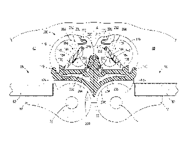
100231 FIG. 4 illustrates another light assembly 200 for use in the
merchandiser 10. In
particular, the light assembly 200 is placed in the merchandiser 10 on
mullions 55 that are
located between adjacent doors 65, whereas the light assembly 100 is placed in
the
merchandiser 10 at corner mullions 55. The illustrated light assembly 200 is
similar to the
light assembly 100 and like elements are given the same reference numerals.
100241 With reference to FIG. 4, the illustrated light assembly 200
includes two light
sources 108 and a light fixture or housing or base 204 ("referred to as the
"base 204" for
purposes of description). The base 204 is non-metallic and acts as an
insulator that can be
integrally formed with the mullion 55, or separately coupled to the mullion
55.
100251 The illustrated base 204 is hollow and supports the light sources
108, a heat guide
212, and lenses 116 disposed over the light sources 108. More specifically,
the base 204
centered on the mullion 55 and is symmetrical about a plane A that is
perpendicular to the
surface of the glass 80 (and illustrated as generally perpendicular to the
mullion 55). The base
204 has a projection 220 extending outward from the mullion 55, and lateral
extensions 224
extending away from each other in a direction generally perpendicular to the
projection 220
(across the mullion 55). The projection 220 has a first cavity 226 on a distal
end of the
projection 220, and opposed second cavities 228 disposed on the sides of the
projection 220
(e.g., adjacent or at the junctures between the projection 220 and the lateral
extensions 224).
The projection 220 also has flexible arms 232 that extend toward the lateral
extensions 224
(generally downward as viewed in FIG. 4) and that encloses part of the second
cavities 228.
Each lateral extension 224 has the first retainer channel 136 and the second
retainer channel
140.
100261 The heat guide 212 is attached to the base 204 and is shaped to be
supported on
the base 204 and to partially support the light sources 108 and the lenses
116. The heat guide
212 is formed of a heat-conductive material (e.g., metal, metal composite,
etc.) and is
exposed to or positioned in communication with cold air in the product display
area 40.
100271 With continued reference to FIG. 4, the heat guide 212 is
symmetrical about the
plane A, and therefore has a first support 252 and symmetrical second supports
256 spaced
apart from the first support 252 to define slots 260. The first support 252
defines one wall of
the corresponding slot 260 and is coupled to the projection 220 within the
first cavity 226.
The second support 256 defines another wall of the slot 260 generally opposite
the first wall
6
CA 02937149 2016-07-15
WO 2015/116346
PCT/US2015/010024
and is coupled to the projection 220 within the second cavity 228. When the
heat guide 212 is
attached to the base 204, the flexible arm 232 is positioned in the slot 260
and held in place
by the first and second supports 252, 256. A corner or ridge 264 defined on
each second
support 256 and the distal end of the corresponding flexible arm 232
cooperatively define a
snap feature or snap-fit engagement that retains the heat guide 212 on the
base 204 until it is
desired that the heat guide 212 be removed.
100281 The heat guide 212 also has support arms 268 that extend from the
main body of
the heat guide 212, and lens supports 272 disposed on an outer end of the heat
guide 212. A
board slot 276 is disposed in the heat guide 212 adjacent (below, as viewed
FIG. 4) the lens
support 272 to support the other longitudinal edge of the board 144. Each
support arm 268 is
curved and defines a pedestal that supports the light source 108. Each lens
support 272
defines a channel 280 to support an edge of the lens 116. As illustrated, the
edges of the
lenses 116, the extensions 224, and the lens supports 272 cooperatively engage
each other to
retain the respective lenses 116 in place. The lenses 116 protect the light
source 108 from
debris and moisture, and can refract or diffuse light emanating from the LEDs
148.
[0029] The light assembly 200 also includes thermal recovery devices 184
that are
positioned between the respective light sources 108 and the heat guide 212. As
illustrated, the
heat guide 212 forms a bridge between the thermal recovery device 184 and cold
air in the
product display area 40. The illustrated thermal recovery device 184 is a
thermo-electric
generator that generates power based on a temperature difference between the
board 144 and
the heat guide 212.
100301 Although the heat guide 212 is described in detail with regard to
the shape
illustrated in FIG. 4, it should be appreciated that the heat guide 212 can
have other shapes as
long as the heat guide 212 forms a bridge between cold air in the product
display area 40 and
the thermal recovery device 184 such that power can be generated based on the
temperature
difference between the light source 108 and the heat guide 212.
10031] In operation, the thermal recovery device 184 measures the
temperature difference
between the heat guide 112 and the light source 108. Because the heat guide
112 is exposed
to the cold air in the product display area 40 and conducts heat, the
temperature of the heat
guide 112 adjacent the first portion 188 is approximately the same as the
temperature of the
cold air. Heat generated by the LEDs 148 is dissipated at least partially
through the board
7
CA 02937149 2016-07-15
WO 2015/116346
PCT/US2015/010024
144. As such, the second portion 192 is heated to a temperature above the
temperature of the
air in the product display area 40. In some constructions, the temperature of
the second
portion 192 can be approximately the same as the board 144.
100321 The first portion 188 measures a temperature of the heat guide 112.
and the
second portion 192 measures a temperature of the light source 108 at the
underside of the
board 144. In general, the product display area 40 is refrigerated to an air
temperature
between approximately -35 C and 10 C, (i.c. approximately 238K to 283K),
although other
temperature ranges are possible and considered herein. Due to the heat
generated by the
LEDs 148, the second portion 192 is heated such that a temperature difference
of at least
approximately 30 C exists across the thermal recovery device 184.
100331 The thermal recovery device 184 recovers waste heat from light
source 108 and
generates electricity or power from the waste heat to power one or more
components of the
merchandiser 10. More specifically, the thermal recovery device 184 converts
the
temperature difference between the light source 108 and the heat guide 112 to
electrical
energy that can be stored in a storage device 196 (e.g., a battery or battery
pack) or directed
to components needing immediate power. Generally, the electrical power can be
recycled to
lower the power consumption of the merchandiser 10, and may be stored and used
to power
other electrical systems or devices. For example, the power generated by the
thermal
recovery device 184 can be used to at least partially power the light source
108.
[0034] For example, at a measured temperature difference of approximately
10 C (i.e.,
10K) across the thermal recovery device 184, the thermal recovery device 184
can output
approximately 1.0mW of power and an open circuit voltage of approximately
170mV. As
another example, at a measured temperature difference of approximately 50 C.
(i.e., 50K) the
thermal recovery device 184 can output approximately 24mW of power and an open
circuit
voltage of approximately 850mV. Preferably, the measured temperature
difference is at least
30 C (i.e., 30K) such that the thermal recovery device 184 can output
approximately 9mW of
power and an open circuit voltage of approximately 500mV. While the 30 C
temperature
difference has a magnitude that generates power that can be used or stored, a
smaller
magnitude temperature difference (e.g., 10 C or 10K) can generate adequate
power to at least
partially provide electrical energy to the merchandiser 10. One exemplary
thermal recovery
device 184 is Nextreme's ETEG HV37 power generator, which is manufactured by
Nextreme
8
CA 02937149 2016-07-15
WO 2015/116346
PCT/US2015/010024
Thermal Solutions. This power generator has a range between approximately 10 C
and
100 C (i.e., 10K to 100K), and is capable of outputting power in the range of
approximately
1.0mW to 90mW and an open circuit voltage in the range of approximately 175mV
to
1700mV.
10035] The light sources 108 define exemplary heat sources positioned in
the product
display area 40 that can be used to generate electrical power based on the
temperature
differential between the heat source and cold air in the product display area
40. By
positioning the power recovery device 184 between the heat source and the cold
air, waste
heat from the heat source can be recycled or converted to useful electrical
energy. In the
exemplary light assemblies 100, 200 described with regard to FIGs. 2-4, the
LEDs may
produce as much as 80% waste heat during operation (resulting in an external
temperature of
approximately 50 C). By connecting the hot junction (i.e. the second portion
192) of the
thermal recovery device 184 to the cold junction (i.e. the first portion 188),
a temperature
difference (e.g., 30 C) across the device 184, with minimal losses, can be
sustained to at least
partially power the light sources 108 andlor other components of the
merchandiser 10 directly
or via the storage device 196.
100361 Various features and advantages of the invention are set forth in
the following
claims.
9