Note: Descriptions are shown in the official language in which they were submitted.
CA 02937324 2016-07-19
WO 2015/160401
PCT/US2015/011995
QUANTUM HARDWARE CHARACTERIZED BY PROGRAMMABLE BOSE-
HUBBARD HANIILTONIANS
BACKGROUND
The present specification relates to quantum hardware characterized by
programmable Bose-Hubbard Hamiltonians.
SUMMARY
In a computational paradigm of this specification, quantum information is
represented by multimodc quantum hardware, the dynamics of which can be
characterized and controlled by a programmable many-body quantum Hamiltonian.
The
multimodc quantum hardware can be programmed as, for example, a quantum
processor for certain machine learning problems. Examples of the quantum
hardware
include neutral atoms on optical lattices, photonic integrated circuits, or
superconducting cavity quantum electrodynamics (QED) circuits, and the
Hamiltonians
characterizing such quantum hardware include dissipative or non-dissipative
Bose-
Hubbard Hamiltonians.
The solution to a machine optimization problem can be encoded into an energy
spectrum of a Bose-Hubbard quantum Hamiltonian. For example, the solution is
encoded in the ground state of the Hamiltonian. Through an annealing process
in which
the Hamiltonian evolves from an initial Hamiltonian into a problem
Hamiltonian, the
energy spectrum or the ground state of the Hamiltonian for solving the problem
can be
obtained without diagonalizing the Hamiltonian. The annealing process may not
require
tensor product structure of conventional qubits or rotations and measurements
of
conventional local single qubits. In addition, quantum noise or dechoerence
can act as a
recourse to drive the non-equilibrium quantum dynamics into a non-trivial
steady state.
The quantum hardware can be used to solve a richer set of problems as compared
to
quantum hardware represented by an Ising Hamiltonian. Furthermore, instead of
the
binary representations provided by the Ising Hamiltonians, constraint
functions of
problems to be solved can have a digital representation according to the
density of
states in Cavity QED modes.
In general, in some aspects, the subject matter of the present disclosure can
be
embodied in apparatuses that include: a first group of superconducting
cavities each
configured to receive multiple photons; a second group of superconducting
cavities
1
CA 02937324 2016-07-19
WO 2015/160401
PCMJS2015/011995
each configured to receive multiple photons; and multiple couplers, in which
each
coupler couples one superconducting cavity from the first group of
superconducting
cavities with one superconducting cavity from the second group of
superconducting
cavities such that the photons in the coupled superconducting cavities
interact, and in
.. which a first superconducting cavity of the first group of superconducting
cavities is
connected to a second superconducting cavity of the second group of
superconducting
cavities, such that photons of the first and second superconducting cavities
are shared
by each of the first and second superconducting cavities, the first
superconducting
cavity is coupled to one or more of the other superconducting cavities of the
first group
of superconducting cavities to which the second superconducting cavities are
coupled,
and the second superconducting cavity is coupled to one or more of the other
superconducting cavities of the second group of superconducting cavities to
which the
first superconducting cavities are coupled.
Various implementations of the apparatuses are possible. For example, in some
implementations, each coupler is configured to annihilate a photon in one
superconducting cavity and create a photon in a different superconducting
cavity.
In some implementations, at least one of the couplers includes a Josephson
junction.
In some implementations, a Hamiltonian characterizing the apparatus is:
Ei hini + Ei tii(aaj + h. c.) + EjUini(ni ¨ 1), in which ni is a particle
number
operator and denotes occupation number of a cavity mode i, c4 is a creation
operator
that creates a photon in cavity mode i, a1 is an annihilation operator that
annihilates a
photon in cavity mode j, hi corresponds to a site disorder, U, corresponds to
an on-site
interaction, tz,j are the hopping matrix elements, and h.c. is hermitian
conjugate. In
some implementations, the multiple couplers are trained to produce an output
desired
probability density function at a subsystem of interest at an equilibrium
state of the
apparatus. In some implementations, the apparatuses are trained as Quantum
BoltLinann machines.
In some implementations, wherein a Hamiltonian characterizing the apparatus
is: hini Ei ti; (4a; + h. c.) + L uini(ni ¨ 1) + Ei Ujinini, in which ni is
a
particle number operator and denotes occupation number of a cavity mode i, a
is a
creation operator that creates a photon in cavity mode i, aj is an
annihilation operator
2
CA 02937324 2016-07-19
WO 2015/160401
PCMJS2015/011995
that annihilates a photon in cavity mode j, hi corresponds to a site disorder,
Ui
corresponds to an on-site interaction, ti,j are the hopping matrix elements,
and h.c. is
hermitian conjugate. The apparatuses can be operable to evolve adiabatically
to a
ground state of a problem Hamiltonian Hp = Ei hini + Ei Uini(ni ¨ 1) +
Li Uijninj. The apparatus can be operable to evolve adiabatically from a Mott-
insulator state to a superfluid state, in which an initial Hamiltonian of the
apparatus is
Hi =>j to, (ait a j + h. c.). The apparatus can be operable to evolve
adiabatically from
a Mott-insulator state to a ground state of a problem Hamiltonian Hp = E, hini
+
Uini(n, ¨ 1) + id Uoinj, in which an initial Hamiltonian of the apparatus is
t
Hi = Ei ai + h. c.).
In some implementations, the apparatus is configured to respond to an external
field 40 and a Hamiltonian characterizing the apparatus in the external field
is:
Ei hini + i,j t1i(a7 aj + h. c.) + L Uini(ni ¨ 1) + Ei[c(t)at + c(tyai] + HsB,
in
which HsB = EiE,Pci,v(aibvt + ict;l.b.õ) + ai(b, + bin] , and in which ni
is a
.. particle number operator, e(t) is a slowly-varying envelope of an
externally applied
field to compensate for photon loss, HSR is a Hamiltonian of the interaction
between the
apparatus and a background bath in which the apparatus is located, by, and
bpi. are
annihilation and creation operators for a bosonic background bath environment,
Ki iv is
a strength of apparatus-bath interactions corresponding to exchange of energy,
hi
corresponds to a site disorder, Ui corresponds to an on-site interaction, t1,1
are the
hopping matrix elements, and Aix corresponds to a strength of local photon
occupation
fluctuations due to exchange of phase with the bath. The apparatus can be
operable to
be dissipatively-driven to a ground state of a problem Hamiltonian.
In some implementations, at least one cavity is a 2D cavity. For example, each
cavity can be a 2D cavity.
In some implementations, at least one cavity is a 3D cavity. For example, each
cavity can be a 3D cavity.
In some implementations, each superconducting cavity in the first group of
superconducting cavities is connected to a superconducting cavity in the
second group
of superconducting cavities.
In general, in other aspects, the subject matter of the present disclosure can
be
embodied in methods that include providing an apparatus having: a first group
of
3
superconducting cavities each configured to receive multiple photons; a second
group
of superconducting cavities each configured to receive multiple photons; and
multiple
couplers, in which each coupler couples one superconducting cavity from the
first
group of superconducting cavities with one superconducting cavity from the
second
group of superconducting cavities such that the photons in the coupled
superconducting
cavities interact, and in which a first superconducting cavity of the first
group of
superconducting cavities is connected to a second superconducting cavity of
the second
group of superconducting cavities, such that photons of the first and second
superconducting cavities are shared by each of the first and second
superconducting
cavities, the first superconducting cavity is coupled to one or more of the
other
superconducting cavities of the first group of superconducting cavities to
which the
second superconducting cavities are coupled, and the second superconducting
cavity is
coupled to one or more of the other superconducting cavities of the second
group of
superconducting cavities to which the first superconducting cavities arc
coupled. The
apparatus can be provided in an initial Mott-insulated state. The methods can
further
include causing a quantum phase transition of the apparatus from the initial
Mott-
insulator state to a superfluid sate; and adiabatically guiding the apparatus
to a problem
Hamiltonian.
Various implementations of the methods are possible. For example, in some
implementations, the methods can further include causing a quantum phase
transition of
the apparatus from the superfluid state to a final Mott-insulator state and
reading the
state of each superconducting cavity in the apparatus.The details of one or
more
embodiments of the subject matter of this specification are set forth in the
accompanying drawings and the description below.
BRIEF DESCRIPTION OF THE DRAWINGS
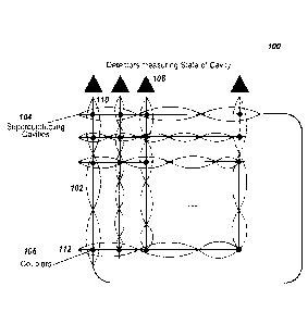
FIG. 1 is a schematic of an example structure of quantum hardware.
FIG. 2A is an example of a selected connection in quantum hardware.
FIG. 2B is an example of a full connection in quantum hardware.
4
Date Recue/Date Received 2020-08-26
CA 02937324 2016-07-19
WO 2015/160401
PCMJS2015/011995
FIG. 3 is a flow diagram of an example process for encoding a problem in a
Hamiltonian containing density-density interactions and programming quantum
hardware.
FIG. 4 is a flow diagram of an example process for encoding a problem in a
dissipative-driven Hamiltonian and programming quantum hardware.
DETAILED DESCRIPTION
FIG. 1 is a schematic of an example structure of quantum hardware 100 that can
be characterized by programmable Bose-Hubbard Hamiltonians. The quantum
hardware 100 includes QED cavities 104 arranged in columns 110, and lines 112.
At
least some pairs of the QED cavities, such as cavities 110 and 112, are
coupled to each
other through coupler 106. The QED cavities can be superconducting waveguide
cavities restricted in dimensionality, e.g., to 1D, 2D or 3D. The couplers 106
can be
inductive couplers, and the hardware can be configured with resistors and
inductors.
The couplers 106 can be Josephson couplers, and in an example, a Josephson
coupler is
constructed by connecting two superconducting elements separated by an
insulator and
a capacitance in parallel.
The cavities contain photons in optical modes 102. The cavities can receive a
variable amount of photons when the quantum hardware is initialized, or during
the use
of the quantum hardware. A coupler 106 between two cavities allows the photons
of the
two cavities to interact with each other. For example, the coupler can create
or
annihilate photons in a cavity, or move photons between cavities. Each cavity
in the
hardware 100 can be used as a logical computation unit. The number of photons
in a
cavity mode of the cavity can be read using photon detectors 108.
In some implementations, the quantum hardware 100 includes a fully connected
network of superconducting cavities 104. In this network, each cavity is
coupled with
all other cavities through couplers 106. In other implementations, selected
pairs of
cavities are coupled with each other. The selection can be made based on the
need for
the quantum computation and the physical confinement of the hardware.
FIG. 2A is an example of a selected connection in quantum hardware. The
hardware includes cavities A, B, C, D, E, F, G, and H, and pairs of cavities
are coupled
through couplers 208. Cavities "A" 202 and "E" 204 are selected to be
connected
through a connection 206, so that effectively, they become the same cavity.
That is, the
5
CA 02937324 2016-07-19
WO 2015/160401 PCMJS2015/011995
connection can be considered an extension of the cavity QED mode. Without the
connection 206, the cavity "A" is coupled to cavities "E", "F", "G", and "H,"
but not to
cavities B, C, and D.
Effectively, in this example, cavity "A" is coupled to all other cavities of
the
hardware. However, cavities "B"-"H" are only coupled to selected cavities of
the
hardware. To increase the number of cavities each cavity is coupled to,
additional
connections similar to the connection 206 can be added. The total amount of
interaction between cavities in the hardware can be increased.
An example of a fully connected network is shown in FIG. 2B. FIG. 2B
includes connections between "E" and "A" 212, "F" and "B" 214, "G" and "C"
216,
and "H" and "D" 218. The network of FIG. 2B therefore allows for each cavity
to
interact with all other cavities.
The hardware of FIGS. 1, 2A, and 2B can be characterized by a Bose-Hubbard
Hamiltonian:
H= + =i(al a. + h. c.) + ¨ 1)
L I
where ni is the particle number operator and denotes the occupation number of
a cavity
mode i, a is a creation operator that creates a photon in cavity mode i, aj is
an
annihilation operator that annihilates a photon in cavity mode j, hi
corresponds to a site
disorder, Ui corresponds to an on-site interaction, ti,1 are the hopping
matrix elements,
and h.c. is the hermitian conjugate.
The hardware of FIGS. 1, 2A, and 2B, characterized by the Bose-Hubbard
Hamiltonian above, can be used to determine solutions to problems by training
the
hardware as a Quantum Boltzmann Machine for probabilistic inference on Markov
Random Fields. For example, a problem can be defined by a set of observables
yi, e.g.,
photon occupation number at a cavity of the hardware, and a goal is to infer
underlying
correlations among a set of hidden variables xi. Assuming statistical
independence
among various pairs of y, and Xi, the joint probability distribution would be
p ((xi}, fyi}) = I I Oij (xi, xj)fj ai(xi,yi) ,
where Z is the partition function (which, for a given system with a fixed
energy
function or a given Hamiltonian, is constant), Oi j (xi, xj) is a pairwise
correlation, and
a,(xi,yi) is the statistical dependency between a given pair of yi and xi.
6
CA 02937324 2016-07-19
WO 2015/160401 PCMJS2015/011995
In training the hardware, certain cavity modes can act as the visible /
observable
input nodes of the Markov Random Field and can be used to train one or more of
the
Josephson couplers, which connect the hidden nodes XI, to reproduce certain
probability
distribution of outcomes at the output visible nodes)),
For example, the training can be such that the delocalized energy ground state
of the Bose-Hubbard model for each input state can have a probability
distribution over
the computational, i.e., localized, basis that resembles the output
probability
distribution function (PDF) of the training example, i.e., p({x1}, fy,}).
Thus, the
thermalized state of the hardware trained as a Quantum Boltzmann Machine can
be
sampled to provide a probabilistic inference on the test data according to the
Boltzmann
distribution function.
For example, an energy function can be defined:
E axi}, fyi}) = ¨ yo
where the nonlocal pairwisc interactions t11 (x, xj) = xj) , and
.. disordered local fields hi(xi, yi) = ai(xi,yi).
The Boltzmann distribution of the above energy function is then:
1 E(fx,i,fyil)
P (tx),{Y i}) =e T
where Z is the partition function.
In some other implementations, the quantum hardware of FIGS. 1, 2A, and 2B
can be engineered or controlled to allow an additional type of coupling
between the
coupled cavities characterized by density-density interactions. With density-
density
interactions, an additional term can be added to the Bose-Hubbard Hamiltonian:
UijninJ.,
The addition of the density-density interaction term to the Bose-Hubbard
Hamiltonian can allow construction of a problem Hamiltonian in which the
solution of
a wide variety of problems can be encoded. For example, constraint functions
of
problems can have a digital representation according to the density of states
in cavity
QED modes with density-density interactions.
To account for photon loss in the above Hamiltonian, in some implementations
.. the hardware is driven with additional fields to compensate for the loss.
7
CA 02937324 2016-07-19
WO 2015/160401 PCMJS2015/011995
To provide the density-density interaction term in the Hamiltonian, the
quantum
hardware can be engineered (an example process of using the additionally
engineered
hardware is shown in FIG. 3) or by controlling the hardware using a
dissipative-driven
method (an example process of using the controlled hardware is shown in FIG.
4).
Using the quantum hardware of FIG. 1 as an example, the quantum hardware
can additionally be engineered to include, e.g., Kerr non-linearity with
Josephson
Junction couplers, the Stark effect, or continuous-time C-phase gates between
cavities.
The modified Hamiltonian characterizing the additionally engineered hardware
is therefore:
t
Htotal = h1n1+ a] + h. c.) + ¨ 1) +
where the final term is the density-density interactions between cavities i
and j.
In use for adiabatic computation, a time dependent Hamiltonian can be
represented as:
Htotal = (1 ¨ s)Hi + sHp ,
where s is a control parameter and can be a linear function of time, H, is the
initial
Hamiltonian:
H =Iti] (ali"a] + h. c.),
and Hp is the problem Hamiltonian into which the selected problem is encoded:
Hp = Ei hini + Ei Uini(ni ¨1) + Ei,] Uiinini
When s = 0, the hardware is placed into an initial ground state that is known.
The hardware is then quais-adiabatically guided to s = 1, moving the hardware
to the
ground state of the Hamiltonian encoded by the problem.
FIG. 3 is a flow diagram of an example process 300 for encoding a problem in a
Hamiltonian containing density-density interactions and programming quantum
hardware.
In solving a given problem, e.g., an optimization problem, a problem modeled
as a Markov Random Field, or an NP-Hard problem, the hardware undergoes a
quantum phase transition from a Mott-insulator state to a superfluid state
(step 302).
The hardware is initially in an insulated state with no phase coherence, and
with
localized wavefunctions only. The many-body state is therefore a product of
local Fock
states for each cavity in the hardware:
8
CA 02937324 2016-07-19
WO 2015/160401 PCMJS2015/011995
= ft a0) ,where N is the number of photons, and i is the cavity
mode.
The hardware undergoes a quantum phase transition to a superfluid state so
that
the wavefunctions are spread out over the entire hardware:
111'sF) aiN10)
The hardware is adiabatically guided to a problem Hamiltonian (step 304). That
is, the hardware is moved from the s=0 state, to the s=1 state as explained
above.
At the end of the annealing process, the hardware transitions from a
superfluid
state to a non-trivial Mott-insulator state that can capture the solution to
the problem
(step 306).
The quantum state of the entire hardware is read out (step 308) and can be
processed by a classical computer to provide solutions to the given problem.
For
example, the state of each cavity is determined by the photon occupation
number of
each cavity mode. The process 300 can be repeated multiple times for the given
problem to provide solutions with a statistical distribution.
Alternatively, using the quantum hardware of FIG. 1 as an example, the
dynamical effects of density-density interactions can be achieved by an
interplay of the
Bose-Hubbard Hamiltonian with cavity photon number fluctuations induced by an
auxiliary external field. The combination of the hardware and the auxiliary
external
field is called a dissipative-driven hardware, and the Hamiltonian describing
the
dissipative-driven hardware is:
HBH = + Itii(ct7 ai + h. c.) + ¨ 1) + 1[E(t)a:l. + E(t)*
+ HSB
where c(t) is a slowly-varying envelope of an externally applied field to
compensate for photon loss, and HsB is the Hamiltonian of the interaction
between the
hardware and the background bath in which the hardware is located:
HSB = II[Ki,v(aibvf + bv) + ai(bv +
t v
where bv, and bvt are annihilation and creation operators for the bosonic
background bath environment, Ki,v is the strength of hardware-bath
interactions
corresponding to the exchange of energy, hi corresponds to a site disorder, U,
9
CA 02937324 2016-07-19
WO 2015/160401 PCMJS2015/011995
corresponds to an on-site interaction, ti,J are the hopping matrix elements,
and k,
corresponds to the strength of local photon occupation fluctuations due to
exchange of
phase with the bath.
Using the dissipative-driven hardware, a solution to a problem can be
.. determined without adiabatically guiding the hardware to the ground state
of a problem
Hamiltonian as in the process 300 of FIG. 3. The dissipative-driven hardware
is
eventually dominated by dissipative dynamics, defining a non-trivial steady
state in
which the solution to a problem is encoded.
FIG. 4 is a flow diagram of an example process 400 for encoding a problem in a
dissipative-driven Hamiltonian and programming quantum hardware.
The hardware is programmed for a problem to be solved (step 402). In some
implementations the problem is an optimization problem or an inference task
and is
mapped to a Markov Random Field. For example, a problem can be defined by a
set of
observables yi, e.g., photon occupation number at a cavity of the hardware,
and the goal
is to infer underlying correlations among a set of hidden variables xi.
Assuming
statistical independence among pair y, and Xi, the joint probability
distribution would be:
p(fx,), fyi}) = I Oid (xi, xj) fj a1(x1,yi) ,
where Z is a normalization constant, Oi j (xi, xj) is a pairwise correlation,
and a1 (x1, yi)
is the statistical dependency between a given pair of yi and xi.
In many classes of machine learning problems, e.g., computer vision, image
processing, and medical diagnosis, the goal of the problems is to compute
marginal
probabilities:
P (x N) = = = = P (tx t} [y})
xl x2 XN-1
Using a density-matrix formulation, the marginal probabilities can be computed
from the dynamics of the dissipative-driven hardware in a quantum trajectory
picture:
dp
dt = ¨i[HBH + HLS Hdecoh, Pl 1i = ='al:coP ata. + AlaiPait,
, õLi
where [ ] is the commutator, p is the density matrix, HBH is the Hamiltonian
describing
the dissipative-driven hardware, HLS is the Lamb shift, Hdecoh is an anti-
Hermitian term
proportional to the dechoerence rate of the hardware that leads to relaxation
in the fixed
excitation manifold and can be the Fourier transform of the bath correlation
functions;
CA 02937324 2016-07-19
WO 2015/160401
PCMJS2015/011995
is a tensor describing the quantum jump rate among fixed-excitation manifolds,
and Ai is a tensor describing quantum jump rates between fixed-excitation
manifolds.
The dechoerence of the hardware is gradually increased to drive the dynamics
of the hardware to a classical regime steady state of dissipative dynamics
that encodes
the solution to the computational problem (step 404). After increasing the
dechoerence,
the dynamics of the dissipative-driven hardware can be simplified to:
dp
¨¨= 2HaecohP + r= = .'ata 'Pata= dt
Local marginal probabilities can then be determined by the hardware and in
some implementations a classical computer (step 406):
dtr [Pmp]
2tr[Pm1 decohPl 1L= F ,tr[al:a 711 ata.,p]
dt , J t
i,i',j,j'
where trl j is the trace operation which in a density-matrix formulation is
used
to determine the expectation value of an operator, and P. is a projector
operator
corresponding to the occupation density of a local cavity mode m.
The second term above retains density-density interactions between photons in
a
cavity mode i and in a cavity mode/ that contribute to the number of photons
in the
visible cavity mode In. The second term further retains the ji'tensor
which can be
related to a Markov transition matrix, which is a matrix used in the problem
if the
problem can be described as a Markov Random Field.
In some implementations, the problem, e.g., a probabilistic inference, can be
encoded in a quantum probability distribution of the dissipative Bose-Hubbard
Hamiltonian or its extended engineered version; that is using the concept of
quantum
graphical models.
While this specification contains many specific implementation details, these
should not be construed as limitations on the scope of any invention or of
what may be
claimed, but rather as descriptions of features that may be specific to
particular
embodiments of particular inventions. Certain features that are described in
this
specification in the context of separate embodiments can also be implemented
in
combination in a single embodiment. Conversely, various features that are
described in
the context of a single embodiment can also be implemented in multiple
embodiments
separately or in any suitable subcombination. Moreover, although features may
be
11
CA 02937324 2016-07-19
WO 2015/160401
PCT/1JS2015/011995
described above as acting in certain combinations and even initially claimed
as such,
one or more features from a claimed combination can in some cases be excised
from
the combination, and the claimed combination may be directed to a
subcombination or
variation of a subcombination.
Similarly, while operations are depicted in the drawings in a particular
order,
this should not be understood as requiring that such operations be performed
in the
particular order shown or in sequential order, or that all illustrated
operations be
performed, to achieve desirable results. In certain circumstances,
multitasking and
parallel processing may be advantageous. Moreover, the separation of various
hardware modules and components in the embodiments described above should not
be
understood as requiring such separation in all embodiments, and it should be
understood that the described program components and hardwares can generally
be
integrated together in a single software product or packaged into multiple
software
products.
Particular embodiments of the subject matter have been described. Other
embodiments are within the scope of the following claims. For example, the
actions
recited in the claims can be performed in a different order and still achieve
desirable
results. As one example, the processes depicted in the accompanying figures do
not
necessarily require the particular order shown, or sequential order, to
achieve desirable
results. In some cases, multitasking and parallel processing may be
advantageous.
12
SUBSTITUTE SHEET (RULE 26)