Note: Descriptions are shown in the official language in which they were submitted.
CA 02937488 2016-07-29
SEQUENTIAL RE-COMPLETIONS OF HORIZONTAL WELLS IN
UNCONSOLIDATED SAND RESERVOIRS TO INCREASE NON-THERMAL
PRIMARY HEAVY OIL RECOVERY
Field of the Invention
[0001] The present invention relates to methods and systems for treating
horizontal wells to
enhance recovery of oil. In particular, the present invention relates to
sequential re-
completions of horizontal wells in unconsolidated sand reservoirs to increase
non-thermal
primary heavy oil recovery,
Background
[0002] Horizontal wells were drilled in non-thermal heavy oil reservoirs with
the expectation .
that they would recover several times the volume of off-setting vertical
wells, because they
contact significantly more reservoir than vertical wells.
[0003] However, it has been found that horizontal wells only recover
approximately the same
volume of oil as a single off-setting vertical well. Horizontal completions
typically use a
slotted liner, and geomechanical phenomena associated with use of the liner in
an effort to
prevent sand inflow leads to sand compaction, which prematurely terminates
inflow of oil.
Attempts to backtlush the sand from the liner are costly and short lived.
[0004] Attempts to induce sand inflow such as larger slot sizes along the
length of the liner or
. long sections of perforations with the pump intake landed at the liner top
have been
unsuccessful. The flow rates and bottom hole pressure are typically too low to
carry sand to
the pump intake. Sand settles out in the liner leading to costly and repeated
sand clean-outs
1
CA 02937488 2016-07-29
with little to show in incremental recovery. Thus, most horizontal wellbores
in a non-thermal
heavy oil well do not justify the additional cost of drilling and completion
over traditional
vertical wellbores.
[0005] In Applicant's co-owned Canadian Patent Application No. 2,899,222, a
method of
sequential recompletions with perforations is described which has the
potential to mitigate
many of the difficulties of the prior art. However, with each perforation,
there will be a large
pressure differential between the reservoir and the inside of the liner at the
time of perforating.
There is no way to reduce this differential. With this pressure differential,
and the stimulation
and fluidization of the sand outside the liner, there is likely to be a large
influx of sand. Sand
has been known to flow 30 to 50 meters uphole after perforating when there is
a large
differential. This sand inflow could cause the tubing that transported the
perforating gun to
become stuck inside the liner.
= [0006] Therefore, there is a need in the art for improved methods of oil
recovery from
horizontal wellbores. The potential economic benefit of increasing recovery
from horizontal
wells is significantly greater than with current practices which include
existing horizontal well
completions, vertical wells, non-thermal flood schemes, and other mechanisms
employed to
increase heavy oil recovery.
Summary Of The Invention
[0007] Implementation of embodiments of the present invention may allow
naturally
occurring geomechanical phenomena in unconsolidated sandstone to significantly
increase
recovery of non-thermal heavy oil in a horizontal well. The area drained by
production of a
CA 02937488 2016-07-29
vertical well is much wider than the width of the area drained by a horizontal
well. This
indicates that a horizontal well may increase recovery by re-completing the
well to widen the
drained area along the length of the well to match the width of the drained
area surrounding
vertical wells.
[00081 ln one aspect, the invention may comprise a method of sequentially
recompleting a
horizontal well having a liner, comprising the steps of:
(a) selecting a first re-completion site within the liner, comprising a
perforation interval
for perforation;
(b) perforating the liner within the selected perforation interval with a
perforating gun
run on a first tubing string comprising isolation devices, a ported tool and a
pump seating
nipple;
(c) without pulling the first tubing string, landing a jet pump on a
production tubing
string onto the pump seating nipple, within the first tubing string; and
(d) pumping p.ower fluid comprising a sand dispersion chemical into the j
et pump either
in the annulus between the first tubing and the production tubing, or within
the production
tubing, thereby producing fluid, sand and power .fluid to the surface.
Preferably, the method comprises the further step of running in a coil tubing
string and
unloading the well, causing sand and fluid inflow through the perforations,
and extracting the
coil tubing string, before landing a jet pump onto the pump seating nipple.
3
CA 02937488 2016-07-29
[0009] In one embodiment, the recompletion steps take place after the well has
been produced
to economic depletion. Alternatively, the recompletion steps may take place to
allow first
production from a well.
[0010] In one embodiment, once the re-completion site is produced to
depletion, the tubing
strings are withdrawn, and a new re-completion site comprising a new
perforation interval,
uphole of the last perforation interval, is chosen and the perforating and
pumping steps are
repeated. The length of the horizontal well may then be treated from toe to
heel by repeating
the perforating and pumping steps in sequential re-completion sites.
Brief Description of the Drawings
[0011] The following drawings form part of the specification and are included
to further
= demonstrate certain embodiments or various aspects of the invention. In
some instances,
embodiments of the. invention can be best understood by referring to the
accompanying
drawings in combination with the detailed description presented herein. The
description and
accompanying drawings may highlight a certain specific example, or a certain
aspect of the
invention. However, one skilled in the art will understand that portions of
the example or
aspect may be used in combination with other examples or aspects of the
invention.
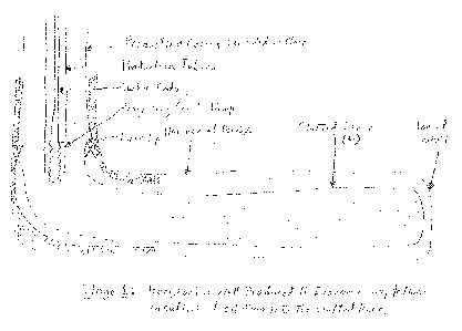
= [0012] Figure 1 shows a cross-sectional schematic of a prior art
completion of a horizontal
well in an unconsolidated sandstone reservoir.
[0013] Figure 2 shows a cross-sectional schematic view of a configuration of a
re-completion
after the well has been produced to economic depletion.
4
CA 02937488 2016-07-29
[0014] Figure 3 shows the well of Figure 2 after perforation and the ported
tool ruptured.
[0015] Figure 4 shows the well of Figure 3 with insertion of a coil tubing
string.
[0016] Figure 5 shows the well of Figure 4 after landing of production tubing
and a jet pump.
Detailed Description
[0017] The present invention comprises methods and systems to continue
production of a
horizontal well, preferably one that has been produced to. economic depletion.
In one
embodiment of the invention, a re-completion site is selected, preferably
which is proximal to
the toe of the well and in a pay or effective pay zone. In one embodiment, the
re-completion
site is selected by reviewing well trajectory in effective pay and the drained
area diameter of
. off-setting vertical wells to maximize recovery from the re-completion.
[0018] As shown in Figure 1, a conventional horizontal wellbore completion
with a slotted
liner (L) is produced to economic depletion, meaning that the value of the oil
inflow into the
liner is less than the costs associated with lifting it to surface, processing
it, and selling it. At
this point, there is no further risk of damaging amounts of sand entering the
liner.
[0019] After a horizontal well has been produced to economic depletion, it is
likely that there
will be sand and sedinient on the bottom of the liner. Open-ended production
tubing pushed
through the liner will ride over the sediment or plow through it for the most
part. However,
isolation tools will push the sediment up in front of them until enough has
accumulated to
prevent forward motion. Therefore, it is preferred to clean out of the length
of the liner (L) to
the toe of the wellbore, to remove debris and ensure that the liner is
undamaged prior to
CA 02937488 2016-07-29
entering it with subsequent equipment. The cleaning step is preferably
undertaken with a fluid
comprising a sand dispersion chemical. Performing a preliminary clean-out step
removes
sand, sediment and any other debris. At the same time, the wellbore is
backfilled with fluid
treated with sand dispersion chemical, which may assist in later trips in and
out of the well,
[0020] Suitable sand dispersion chemicals are well known in the art and
commercially
available, and may include water soluble products such as SS5844TM and/or oil
soluble, water
dispersible products such as SSS6O9TM (Multi-Chem Production Chemicals, a
division of
Halliburton).
= [0021] In one embodiment, the liner is a slotted liner, or a combination
of slotted liner and
blank liner, as is well known in the art. However, embodiments of the present
invention may
be practiced with blank liners throughout the length of the horizontal well.
[0022] After cleaning out the liner, a perforation interval within the re-
completion site is
Selected and perforated as described below and largely in accordance with
conventional
perforating techniques, well known to those skilled in the art, The length of
perforation
interval, perforation diameter, penetration, shot density and phasing are
selected based on
various reservoir and fluid criteria, which is well within the ordinary skill
of one skilled in the
art, In one embodiment, consideration -for the pumping equipment's deployment
and ability to
= remove the sand from the perforations are also factors which are
considered. In one
embodiment, it is preferred to maintain a relatively short perforating
interval, in the range of
less than 5 meters, preferably less than 3 meters, more preferably less than
about 2 meters. A
= 6
CA 02937488 2016-07-29
relatively longer perforation interval may increase the risk of smothering the
perforations with
inflowing sand.,
[0023] The objective of perforation is to create openings in the liner through
which sand and
produced fluids may enter the liner. One preferred method of perforating is
jet perforating
using shaped explosive charges, which is well known to those skilled in the
art. Alternative
methods of perforation are also well known in the art, and include bullet gun
perforation,
. abrasive-jetting of openings such as radial or longitudinal slots using high
pressure abrasive
fluid, and cutting windows.
[0024] In one embodiment, the perforation pattern may comprise 60 degree
phasing with
relatively more (e.g. 20 to 26) shots per meter with larger holes, rather than
90 degree phasing
with fewer shot and deeper smaller holes. This forms a helical pattern of
holes off-set about
every 2 inches in the entire circumference of the liner for ,sand and oil to
flow into the liner
Sand has a tendency to settle faster in horizontal pipe than in vertical pipe
but inflow from the
bottom and sides of the liner, and the increased shot density and hole size
may assist in
disrupting compaction.
[0025] As is well known in the art, stimulation/fluidization fluid may then be
circulated to
mobilize the reservoir sand outside the newly created perforations. The
stimulation/fluidization fluid preferably contains sand dispersion chemical,
and may be in
used in a volume of about fifty cubic meters (350 barrels). The intention is
that the majority of
the sand that will inflow will be treated with sand dispersion chemical. As
long as the sand
can be kept fluidized it reduces the risk of sand compaction.
7
=
CA 02937488 2016-07-29
[0026] In order to avoid the need to trip the detonated perforating gun out of
the hole, and
provide a means for immediate flowback and clean-up after stimulation is
complete, a pump
seating nipple is provided with the tubing string conveying the perforating
device. The
production tubing with the jet pump may be landed a short distance above the
pump seating
. nipple prior to detonating the perforating gun. Additionally, the accuracy
of the location of
the pump intake relative to the perforations may be improved.
[0027] This method also avoids the requirement of a sand clean out or prevents
sand influx
from sticking tubing in the liner after perforating and stimulating, before
being able to put the
well on production.. If sand inflow is heavy enough during this stage, the
cost to remove it
could terminate the entire re-completion before getting the well on
production. The same can
be said of getting the tubing stuck because of the inability to control sand
inflow.
[0028] Isolation devices are placed to isolate a perforation interval, and are
intended to
prevent sand from flowing uphole in the liner outside the first tubing string
that transported
the perforating gun. The isolation devices will contain and direct the
inflowing sand to the
inside of the tubing that transported the perforating gun. To reduce the
possibility of having
to do a sand clean-out inside this tubing, the production string with the jet
pump assembly
could also be run but not landed in the seating nipple before perforating,
rather than run in
after perforating and stimulating or fluidizing the sand, Then, immediately
after
stimulation/fluidization is complete, the production tubing string _may be
lowered to scat the
jet pump assembly into the pump seating nipple, substantially preventing
uncontrolled sand
inflow into either tubing string.
8
CA 02937488 2016-07-29
[0029] Shortly after the end of the stimulation step, for example, within one
hour, a-jet pump
can be landed in the pump seating nipple and started up, slowly at first, to
commence
removing sand inflow. As sand cut stabilizes, the pump may be sped up step-
wise to induce
more sand inflow and increase overall production rate. This step-wise increase
in speeding up
the pump would eventually get the well to maximum drawdown where no more sand
inflow
occurs. In this fashion the pump is both the means of removing the sand and
can supply the
necessary back pressure to provide the operator the means to control the rate
of sand inflow.
[0030] In one embodiment, one significant advantage of this method is that
only one trip into
the well is required as opposed to multiple trips and it avoids the use of
auxiliary equipment.
Thus, the well may be perforated, sand outside the liner may be stimulated and
fluidized, and
sand inflow may be contained and directed. At the same time, the well is in a
position to be
= on production shortly after perforation, and sand clean-out may be per-
formed using
production equipment instead of auxiliary equipment.
[0031] In one embodiment of the method, after an initial sand clean-out to the
toe is
completed, elements are run into the well to perforate the selected location,
as described above
and shown in Figure 2. A tubing (10) conveyed perforating gun (12) is deployed
between
isolation devices (14, 16) at the top and bottom of the gun, which define the
perforation
interval between them. A ported tool (18) having a rupture disk is placed
between the top
isolation device (14) and the top of the perforating gun (12). After the
perforating gun (12) is
fired, fluid is pumped through the tubing (10) at a high enough pressure to
rupture the ported
= tool (18), causing fluid to wash over the fired perforation gun to wash
away sand. The fluid is
.9
CA 02937488 2016-07-29
pumped in large enough volume and high enough rate to enter the formation
through the
freshly made perforations to further break up and disturb any compacted sand
outside the -
liner. In one embodiment, the fluid is an aqueous solution comprising a sand
dispersion
chemical which keeps the sand fluidized, minimizing the risk of getting the
perforating gun
and tubing stuck in the well by compacted sand inflow. The isolation devices
(14, 16) contain
any inflowing sand to a relatively short interval. The isolation devices
(14,16) also contain the
flush fluid to the space covering the perforation gun thereby flushing
inflowing sand back
through the perforations, as well as direct the sand dispersion fluid into the
perforations to
disrupt any sand which has compacted in the perforation openings and outside
the liner. Once
the sand is treated with the sand dispersion chemical there is less likelihood
that it will
compact under any conditions.
[0032] The tubing (10) is landed in the wellhead prior to detonating the
perforating gun (12),
but because it also includes a pump seating nipple (24) between the ported
tool (1.8) and the
upper isolation device (14), it should not need to be extracted again. This
ensures that all the
important elements necessary for effective production of-the well remain
accurately on depth.
[0033] At this stage, instead of tripping out the detonated perforating gun
(12) and first tubing
(10) and re-entering with concentric tubing, a production tubing string (20)
with a jet pump
(28) can be immediately landed in the jet pump seating nipple (24) and the
well can be placed
immediately on production. Alternatively, coil tubing (30) may be run into the
landed tubing
(10) and into the ported sub. The well can then be unloaded with various
fluids and/or gas
CA 02937488 2016-07-29
combinations that will stimulate sand inflow and effect removal of the sand to
surface, as is
shown in Figure 4.
[0034] If the choice is made to run the coil tubing operation, after the sand
in-flow has
diminished to a comfortable level, the coil tubing (30) is extracted, and the
production string
(20) and jet pump (28) arc installed, as is shown in Figure 3,
[0035] The jet pump is landed so that the pump intake is above the
perforations. While this
configuration may result in sand accumulation in the perforations and impeding
inflow,
certain features of the claimed invention may mitigate this possibility,
[0036] The short perforation, for example only a meter long interval, and the
placement of the
ported tool and pump as close to the perforations as physically possible,
about one meter
above the perforations, minimizes the length of a potential sand filled
section. Flush-by fluid
can jet through this and restore flow to the pump intake. Also, the inside
diameter of most
liners (5 inch) relative to the outside diameter of the perforating gun (4
inch) will create an
annular space 0.5 inch to 1.5 inch wide over the length of the perforating
gun. Flow rate inside
this annular space is an order of magnitude greater than flow rate inside open
liner, thus,
. allowing better sand fluidization and mobilization in this zone.
[0037] The isolation devices at the bottom of the perforation gun and just
above the ported
tool not only contain and direct the oily sand inflow into the pump when the
well is on
production, they contain and direct injected flush-by fluid across the
perforating gun and into
the perforations' to remove sand build up when the need arises.
11
CA 02937488 2016-07-29
[0038] In one embodiment, the jet pump (28) is configured to operate in
reverse flow, that is,
power fluid will be pumped down the annulus between the first tubing string
(10) and the
production tubing string (20), and the mixture of produced fluid/sand/power
fluid will be
produced up the production tubing string (20). Suitable jet pumps which
operate on the
venturi effect are well-known to those skilled in the art, and are readily
commercially
available.
[0039] This reverse circulation may restrict abrasive wear from the sand to
the inside of the
first tubing. Also, in the event of a downhole tubing leak, sand-laden fluid
will not spew out
into the liner to stick the tubing in the liner. Furthermore, in the event
that the inner tubing
string (22) does plug up with sand it can be stripped from the well by a
service rig to remove
the blockage without having to remove both strings simultaneously.
Alternatively, the jet
pump (28) can be operated in a forward configuration, where power fluid is
pumped down the
production tubing string (20) and returns up the annulus between the first
tubing string (10)
and the production tubing string (20),
[0040] Also, the production tubing string (20) can be hoisted by a flush-by
rig so that fluid
with sand dispersion chemical can be pumped down the first tubing string (10)
to displace
sand away from the inlet which is now the ported sub, and over the detonated
perforating gun
which was left in the well, and out the perforation ports into the area
outside the perforated
liner. The ported tool may be designed to direct injected flush-by fluid to
the area where sand
might likely be accumulated or compacted, within the area confined by the
isolation devices.
Before hoisting, the pump seating nipple bore forms a metal to metal fluid
seal with the
12
=
CA 02937488 2016-07-29
=
outside of the jet pump assembly so that injected power fluid has to circulate
back to surface
via the production tubing. Lifting the jet pump assembly out of the pump
seating nipple
= disrupts the seal. When the flushing operation is complete, the Flush-by
rig lowers the
production tubing replacing the jet pump assembly in the pump seating nipple
to restore the
seal and production can be resumed. The entire operation may be accomplished
in a few hours
compared to moving on a service rig and auxiliary equipment for a week long
sand clean out
operation.
[0041] Treating the jet pump power fluid with sand dispersion chemical is
preferred. With
methods of the present invention, the horizontal well n-lay produce fluids
which are 70% sand
by volume. While this sand-laden fluid is diluted by the volume of power fluid
when
produced, it is still a large amount of sand to be carried over a very long
distance.
= Conventional techniques such as "rocking" the well could serve to
concentrate the sand, and
eventually lead to sand compaction which would require a service job to
remediate.
Treatment with a sand dispersion chemical assists in preventing such blockages
by keeping
the sand fluidized and moveable.
[0042] In one embodiment, each of the first tubing string (10) and the
production tubing string
(20) comprises jointed tubing, and can be readily extracted by a service rig
for clean out or to
service the jet pump. With jointed pipe, the pipe can be examined for wear as
it is pulled from
the well and only the necessary joints are replaced. Furthermore, each
successive re-
completion requires the tubing strings to be shortened as the move uphole is
made to the next
re-completion perforation interval. If continuous tubing is used, it has to be
cut off and
13
CA 02937488 2016-07-29
discarded. Discarding cut off sections of continuous tubing, as well as an
entire string of
continuous tubing, may be costly and difficult. Jointed pipe that is removed
from the string
during the move uphole can be re-used in the completion of other wells or
stored for
replacement use when other tubing has worn.
. [0043] The re-completion is then produced by pumping power fluid into the
jet pump and
producing a mixture of produced fluid, sand and power fluid up the production
tubing. Sand
dispersion chemical is preferably added to the power fluid to ensure the
produced sand in the
production tubing string remains fluidized to prevent compaction upon
settling.
[0044] When this re-completion reaches economic depletion, the tubing strings
(10, 20) are
pulled and inspected for wear as they are being pulled. The jet pump downhole
components
are inspected and serviced at the surface.
[0045] A new re-completion site, uphole of the previous site is selected for a
new re-
.
completion in the same fashion the first site was selected. In one embodiment,
subsequent re-
' completion sites may be determined by calculating the diameter of the
drained area of the
immediately preceding site, and move uphole by approximately the same a
distance.
Additionally, or alternatively, data from methods such as 3D seismic surveys
may be rendered
to show the depleted area, or data from various types of cased hole logging
may be used to
determine a suitable pay zone for the next re-completion site.
[0046] Once the next site is selected, a perforation configuration and
perforation interval is
selected, and the well is perforated and flushed as in the first re-
completion. The new re-
completion is then produced to depletion. In one embodiment, this process is
repeated until
14
CA 02937488 2016-07-29
all space for re-completions in the horizontal wellbore have been exhausted.
In other words,
the re-completions are repeated towards the heel of the wellbore, until all
available re-
= completions have been performed. In a preferred embodiment, the re-
completions are
performed sequentially, from toe to heel.
Definitions and Interpretation
[0047] The description of the present invention has been presented for
purposes of illustration
and description, bufit is not intended to be exhaustive or limited to the
invention in the form
disclosed. Many modifications and variations will be apparent to those of
ordinary skill in the
art without departing from the scope and spirit of the invention. Embodiments
were chosen
and described in order to best explain the principles of the invention and the
practical
application, and. to enable others of ordinary skill in the art to understand
the invention for
various embodiments with various modifications as are suited to the particular
use
contemplated.
[0048] As used herein, the terms "top", "above", or "upper" and "bottom",
"below" or
"lower", or similar terms, are used to denote the relative position of an
element in the work
. string, and not neceSsarily an indication of vertical position. The upper
end of the work string
is that which is closer to the surface end of the work string, while the
bottom end is that which
is closer to the toe of the well.
[0049] The corresponding structures, materials, acts, and equivalents of all
means or steps
plus function elements in the claims appended to this specification are
intended to include any
CA 02937488 2016-07-29
structure, material, or act for performing the function in combination with
other claimed
elements as specifically claimed.
[0050] References in the specification to "one embodiment", "an embodiment",
etc., indicate
that the embodiment described may include a particular aspect, feature,
structure, or
. characteristic, but nOt every embodiment necessarily includes that aspect, -
feature, structure, or
characteristic. Moreover, such phrases may, but do not necessarily, refer to
the same
embodiment referred to in other portions of the specification. Further, when a
particular
aspect, feature, structure, or characteristic is described in connection with
an embodiment, it is
within the knowledge of one skilled in the art to combine, affect or connect
such aspect,
feature, structure, or characteristic with other embodiments, whether or not
such connection or
combination is explicitly described. In other words, any element or feature
may be combined
with any other element or feature in different embodiments, unless there is an
obvious or
inherent incompatibility between the two, or it is specifically excluded.
= [0051] It is further noted that the claims may be drafted to exclude any
optional element. As
such, this statement is intended to serve as antecedent basis for the use of
exclusive
terminology, such as "solely," "only," and the like, in connection with the
recitation of claim
elements or use of a "negative" limitation. The terms "preferably,"
"preferred," "prefer,"
"optionally," "may," and similar terms are used to indicate that an item,
condition or step
= being referred to is an optional (not required) -feature of the
invention.
16
=
CA 02937488 2016-07-29
[0052] The singular forms "a," an, and "the" include the plural reference
unless the context
clearly dictates otherwise. The term "and/or" means any one of the items, any
combination of
the items, or all of the items with which this term is associated.
[0053] As will be understood by one skilled in the art, for any and all
purposes, particularly in
terms of providing a written description, all ranges recited herein also
encompass any and all
possible sub-ranges and combinations of sub-ranges thereof, as well as the
individual values
making up the range, particularly integer values. A recited range (e.g.,
weight percents or
carbon groups) includes each specific value, integer, decimal, or identity
within the range.
Any listed range can be easily recognized as sufficiently describing and
enabling the same
range being broken down into at least equal halves, thirds, quarters, fifths,
or tenths. As a
non-limiting example, each range discussed herein can be readily broken down
into a lower
= third, middle third and upper third, etc. As will also be understood by
one skilled in the art,
all language such as "up to", "at least", "greater than'', ''less than", "more
than, "or more", and
the like, include the number recited anC1 such terms refer to ranges that can
be subsequently
broken down into sub-ranges as discussed above. In the same manner, all ratios
recited herein
also include all sub-ratios falling within the broader ratio,
[0054] The term "about" can refer to a variation of IL 5%,, 10%, + 20%, or +
25% of the
value specified. For example, "about 50" percent can in some embodiments carry
a variation
from 45 to 55 percent. For integer ranges, the term "about" can include one or
two integers
greater than and/or less than a recited integer at each end of the range.
Unless indicated
otherwise herein, th term "about" is intended to include values and ranges
proximate to the
17
CA 02937488 2016-07-29
recited range that are equivalent in terms of the functionality of the
composition, or the
embodiment,
18