Note: Descriptions are shown in the official language in which they were submitted.
CA 2938133 2017-04-24
DESCRIPTION
A FUEL CELL SYSTEM WITH WETNESS AND
ANODE GAS CONCENTRATION CONTROL
TECHNICAL FIELD
[0001] The present
invention relates to a fuel cell system with a fuel cell for
generating electrical power upon being supplied with anode gas and cathode
gas.
BACKGROUND ART
[0002] JP2009-
210314A discloses a fuel cell system provided with an
arrangement for calculating an electrostatic capacitance of a capacitor
component of a fuel cell and diagnosing a degree of wetness (water content) of
an electrolyte membrane of the fuel cell on the basis of the calculated
electrostatic capacitance.
SUMMARY OF INVENTION
[0003] On the other
hand, the inventors of the present application found
out that a combined capacitance of an electric double layer capacitance on an
anode electrode side of a fuel cell and an electric double layer capacitance
on a
cathode electrode side changed on the basis of not only a degree of wetness of
an electrolyte membrane, but also an anode gas concentration in the fuel cell.
[0004] Thus, in the
above fuel cell system not configured to address the
effect of the anode gas concentration on the combined capacitance of the fuel
cell, it is not possible to detect the dry-out (abnormal drying) of the
electrolyte
membrane of the fuel cell and a decrease of the anode gas concentration in the
fuel cell in distinction.
[0005] One object
of the present invention is to provide a fuel cell system
capable of detecting a state of an anode gas concentration in a fuel cell in
1
CA 02938133 2016-07-27
distinction from a degree of wetness of an electrolyte membrane of the fuel
cell
and properly responding to the state of the anode gas concentration.
[0006] According to one aspect of the present invention, a fuel cell system
is
provided, which has a fuel cell for generating electrical power upon being
supplied with anode gas and cathode gas. The fuel cell system includes a
wetness control state determination unit configured to determine whether or
not a wetness control of controlling a degree of wetness of an electrolyte
membrane of the fuel cell is normally executed, a combined capacitance
calculation unit configured to calculate a combined capacitance of the fuel
cell,
and an anode gas concentration control unit configured to determine that an
anode gas concentration in the fuel cell has decreased or execute a control
for
increasing the anode gas concentration if the combined capacitance of the fuel
cell is smaller than a predetermined value when the wetness control is
determined to be normally executed.
BRIEF DESCRIPTION OF DRAWINGS
[0007] FIG. 1 is a perspective view of a fuel cell according to an
embodiment
of the present invention,
FIG. 2 is a sectional view along II-II of the fuel cell of FIG. 1,
FIG. 3 is a schematic configuration diagram of a fuel cell system
according to the embodiment of the present invention,
FIG. 4 is a diagram showing an equivalent circuit of the fuel cell,
FIG. 5 is a flow chart of a management control executed by a controller of
the fuel cell system,
FIG. 6 is a flow chart showing a wetness degree determining internal
impedance HFR calculation process performed by the controller,
FIG. 7 is a graph showing a calculation principle of a combined
capacitance of a fuel cell stack, and
2
CA 02938133 2016-07-27
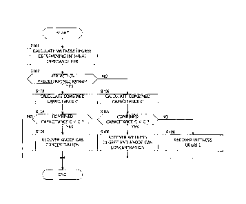
FIG. 8 is a flow chart showing a combined capacitance C calculation
process performed by the controller.
DESCRIPTION OF EMBODIMENT
[00081 Hereinafter, one embodiment of the present invention is described
with reference to the drawings and the like.
[00091 In a fuel cell, an electrolyte membrane is sandwiched by an anode
electrode as a fuel electrode and a cathode electrode as an oxidant electrode.
The fuel cell generates electrical power using anode gas containing hydrogen
and supplied to the anode electrode and cathode gas containing oxygen and
supplied to the cathode electrode. Electrode reactions which proceed in both
anode and cathode electrodes are as follows.
[0010] Anode electrode: 2E12¨>4H++4e- ...(1)
Cathode electrode: 4H 4e-+02¨>2H20 ...(2)
The fuel cell generates an electromotive force of about 1 volt by these
electrode reactions (1) and (2).
[0011] FIGS. 1 and 2 are views showing the configuration of a fuel cell 10
according to one embodiment of the present invention. FIG. 1 is a perspective
view of the fuel cell 10. FIG. 2 is a sectional view along II-II of the fuel
cell 10
of FIG. 1.
[0012] As shown in FIGS. 1 and 2, the fuel cell 10 includes a membrane
electrode assembly (MEA) 11, and an anode separator 12 and a cathode
separator 13 arranged to sandwich the MEA 11.
[0013] The MEA 11 is composed of an electrolyte membrane 111, an anode
electrode 112 and a cathode electrode 113. The MEA 11 includes the anode
electrode 112 on one surface of the electrolyte membrane 111 and the cathode
electrode 113 on the other surface side.
[0014] The electrolyte membrane 111 is a proton conductive ion exchange
3
CA 02938133 2016-07-27
membrane formed of fluororesin. The electrolyte membrane 111 exhibits
good electrical conductivity in a wet state.
[0015] The anode electrode 112 includes a catalyst layer 112A and a gas
diffusion layer 112B. The catalyst layer 112A is a member formed of platinum
or carbon black particles carrying platinum or the like and provided in
contact
with the electrolyte membrane 111. The gas diffusion layer 112B is provided
on the outer side of the catalyst layer 112A. The gas diffusion layer 112B is
a
member formed of carbon cloth having gas diffusion property and electrical
conductivity and provided in contact with the catalyst layer 112A and the
anode separator 12.
[0016] Similar to the anode electrode 112, the cathode electrode 113 also
includes a catalyst layer 113A and a gas diffusion layer 113B. The catalyst
layer 113A is arranged between the electrolyte membrane 111 and the gas
diffusion layer 113B and the gas diffusion layer 113B is arranged between the
catalyst layer 113A and the cathode separator 13.
[0017] The anode separator 12 is arranged on the outer side of the gas
diffusion layer 112B. The anode separator 12 includes a plurality of anode
gas flow passages 121 for supplying anode gas (hydrogen gas) to the anode
electrode 112. The anode gas flow passages 121 are formed as groove-like
passages.
[0018] The cathode separator 13 is arranged on the outer side of the gas
diffusion layer 113B. The cathode separator 13 includes a plurality of
cathode gas flow passages 131 for supplying cathode gas (air) to the cathode
electrode 113. The cathode gas flow passages 131 are formed as groove-like
passages.
[0019] The anode separator 12 and the cathode separator 13 are so
configured that the anode gas flowing in the anode gas flow passages 121 and
the cathode gas flowing in the cathode gas flow passages 131 flow in
directions
4
CA 02938133 2016-07-27
opposite to each other. It should be noted that these gases may flow in the
same direction.
[0020] In the case of using such a fuel cell 10 as a power source for an
automotive vehicle, a fuel cell stack 1 in which several hundreds of fuel
cells 10
are laminated is used since the required electrical power is large. Power for
driving the vehicle can be taken out by configuring a fuel cell system 100
such
that anode gas and cathode gas are supplied to the fuel cell stack 1.
[0021] FIG. 3 is a schematic diagram of the fuel cell system 100 according
to one embodiment of the present invention.
[0022] The fuel cell system 100 includes the fuel cell stack 1, a cathode
gas
supplying/discharging device 2, an anode gas supplying/discharging device 3,
a stack cooling device 4, a power system 5 and a controller 6.
[0023] The fuel cell stack 1 is a laminated battery formed by laminating a
plurality of fuel cells 10 (unit cells). The fuel cell stack 1 generates
electrical
power necessary to drive a vehicle upon being supplied with the anode gas
and the cathode gas. The fuel cell stack 1 includes an anode electrode side
terminal 1A and a cathode electrode side terminal 1B as terminals for taking
out electrical power.
[0024] The cathode gas supplying/discharging device 2 supplies the
cathode gas to the fuel cell stack 1 and discharges cathode off-gas discharged
from the fuel cell stack 1 to outside. The cathode gas supplying/discharging
device 2 includes a cathode gas supply passage 21, a cathode gas discharge
passage 22, a filter 23, an air flow sensor 24, a cathode compressor 25, a
cathode pressure sensor 26, a water recovery device (WRD) 27 and a cathode
pressure regulating valve 28.
[0025] The cathode gas supply passage 21 is a passage in which the
cathode gas to be supplied to the fuel cell stack 1 flows. One end of the
cathode gas supply passage 21 is connected to the filter 23 and the other end
CA 02938133 2016-07-27
is connected to a cathode gas inlet part of the fuel cell stack 1.
[0026] The cathode gas discharge passage 22 is a passage in which the
cathode off-gas discharged from the fuel cell stack 1 flows. One end of the
cathode gas discharge passage 22 is connected to a cathode gas outlet part of
the fuel cell stack 1 and the other end is formed as an opening end. The
cathode off-gas is a mixture of gas containing the cathode gas, steam produced
by the electrode reaction and the like.
[0027] The filter 23 is a member for removing dust, dirt and the like
contained in the cathode gas to be taken into the cathode gas supply passage
21.
[0028] The cathode compressor 25 is provided downstream of the filter 23
in the cathode gas supply passage 21. The cathode compressor 25 supplies
the cathode gas in the cathode gas supply passage 21 to the fuel cell stack 1
by
feeding it under pressure.
[0029] The air flow sensor 24 is provided between the filter 23 and the
cathode compressor 25 in the cathode gas supply passage 21. The air flow
sensor 24 detects a flow rate of the cathode gas to be supplied to the fuel
cell
stack 1.
[0030] The cathode pressure sensor 26 is provided between the cathode
compressor 25 and the WRD 27 in the cathode gas supply passage 21. The
cathode pressure sensor 26 detects a pressure of the cathode gas to be
supplied to the fuel cell stack 1. The cathode gas pressure detected by the
cathode pressure sensor 26 represents a pressure of an entire cathode system
including the cathode gas flow passages of the fuel cell stack 1 and the like.
[0031] The WRD 27 is connected across the cathode gas supply passage 21
and the cathode gas discharge passage 22. The WRD 27 recovers moisture in
the cathode off-gas flowing in the cathode gas discharge passage 22 and
humidifies the cathode gas flowing in the cathode gas supply passage 21 with
6
CA 02938133 2016-07-27
that recovered moisture.
[0032] The cathode pressure regulating valve 28 is provided downstream of
the WRD 27 in the cathode gas discharge passage 22. The cathode pressure
regulating valve 28 is controlled to open and close by the controller 6 and
adjusts the pressure of the cathode gas to be supplied to the fuel cell stack
1.
[0033] Next, the anode gas supplying/discharging device 3 is described.
The anode gas supplying/discharging device 3 supplies the anode gas to the
fuel cell stack 1 and discharges anode off-gas discharged from the fuel cell
stack 1 to the cathode gas discharge passage 22. The anode gas
supplying/discharging device 3 includes a high-pressure tank 31, an anode
gas supply passage 32, an anode pressure regulating valve 33, an anode
pressure sensor 34, an anode gas discharge passage 35, a buffer tank 36, a
purge passage 37 and a purge valve 38.
[0034] The high-pressure tank 31 stores the anode gas to be supplied to the
fuel cell stack 1 in a high-pressure state.
[0035] The anode gas supply passage 32 is a passage for supplying the
anode gas discharged from the high-pressure tank 31 to the fuel cell stack 1.
One end of the anode gas supply passage 32 is connected to the high-pressure
tank 31 and the other end is connected to an anode gas inlet part of the fuel
cell stack 1.
[0036] The anode pressure regulating valve 33 is provided downstream of
the high-pressure tank 31 in the anode gas supply passage 32. The anode
pressure regulating valve 33 is controlled to open and close by the controller
6
and adjusts a pressure of the anode gas to be supplied to the fuel cell stack
1.
[0037] The anode pressure sensor 34 is provided downstream of the anode
pressure regulating valve 33 in the anode gas supply passage 32. The anode
pressure sensor 34 detects a pressure of the anode gas to be supplied to the
fuel cell stack 1. The anode gas pressure detected by the anode pressure
7
CA 02938133 2016-07-27
sensor 34 represents a pressure of an entire anode system including the buffer
tank 36, the anode gas flow passages of the fuel cell stack 1 and the like.
[0038] The anode gas discharge passage 35 is a passage in which the anode
off-gas discharged from the fuel cell stack 1 flows. One end of the anode gas
discharge passage 35 is connected to an anode gas outlet part of the fuel cell
stack 1 and the other end is connected to the buffer tank 36. The anode gas
contains the anode gas not used in the electrode reaction, impurity gas such
as nitrogen having leaked from the cathode gas flow passages 131 to the anode
gas flow passages 121, moisture and the like.
[0039] The buffer tank 36 is a container for temporarily storing the anode
off-gas flowing from the anode gas discharge passage 35. The anode off-gas
pooled in the buffer tank 36 is discharged to the cathode gas discharge
passage 22 through the purge passage 37 when the purge valve 38 is opened.
[0040] The purge passage 37 is a passage for discharging the anode off-gas.
One end of the purge passage 37 is connected to a part of the anode gas
discharge passage 35 upstream of the buffer tank 36 and the other end is
connected to a part of the cathode gas discharge passage 22 downstream of the
cathode pressure regulating valve 28.
[0041] The purge valve 38 is provided in the purge passage 37. The purge
valve 38 is controlled to open and close by the controller 6 and controls a
purge
flow rate of the anode off-gas discharged from the anode gas discharge passage
35 to the cathode gas discharge passage 22.
[0042] When a purge control is executed to open the purge valve 38, the
anode off-gas is discharged to the outside through the purge passage 37 and
the cathode gas discharge passage 22. At this time, the anode off-gas is
mixed with the cathode off-gas in the cathode gas discharge passage 22. By
mixing the anode off-gas and the cathode off-gas and discharging them to the
outside in this way, an anode gas concentration (hydrogen concentration) in
CA 2938133 2017-04-24
- the mixture of gas is set at a value not larger than a discharge allowable
concentration.
[0043]
The stack cooling device 4 is a temperature regulating device for
cooling the fuel cell stack I by cooling water such. as antifreeze and
regulating
the fuel cell stack I to a temperature suitable for power generation. The
stack
cooling device 4 includes a circulation passage 41, a radiator 42, a bypass
passage 43, a
three-way valve 44, a circulation pump 45, a positive temperature coefficient
(PTC) heater
46, an inlet water temperature sensor 47 and an outlet water temperature
sensor 48.
[0044]
The circulation passage 41 is configured as a looped passage in
which the cooling water is circulated. One end of the circulation passage 41
is connected to a cooling water inlet part of the fuel cell stack 1 and the
other
end is connected to a cooling water outlet part of the fuel cell stack 1.
[0045]
The radiator 42 is provided in the circulation passage 41. The
radiator 42 is a heat exchanger for radiating the heat of the cooling water
discharged from the fuel cell stack 1 to outside.
[0046]
The bypass passage 43 is a passage in which the cooling water flows
while bypassing the radiator 42. One end of the bypass passage 43 is
connected to a part of the circulation passage 41 upstream of the radiator 42
and the other end is connected to the three-way valve 44 provided downstream
of the radiator 42 in the circulation passage 41.
[00471
The three-way valve 44 switches a circulation route of the cooling
water according to the temperature of the cooling water. Specifically, if the
temperature of the cooling water is higher than a predetermined temperature,
the three-way valve 44 is switched so that the cooling water discharged from
the fuel cell stack 1 is supplied to the fuel cell stack 1 again through the
radiator 42. In contrast, if the temperature of the cooling water is lower
than
a predetermined temperature, the three-way valve 44 is switched so that the
cooling water discharged from the fuel cell stack 1 is supplied to the fuel
cell
9
CA 02938133 2016-07-27
stack 1 again after flowing along the bypass passage 43.
[0048] The circulation pump 45 is provided downstream of the three-way
valve 44 in the circulation passage 41 and circulates the cooling water.
[0049] The PTC heater 46 is provided in the bypass passage 43. The PTC
heater 46 is energized during the warm-up of the fuel cell stack 1 to increase
the temperature of the cooling water.
[0050] The inlet water temperature sensor 47 is provided near the cooling
water inlet part of the fuel cell stack 1 in the circulation passage 41. The
outlet water temperature sensor 48 is provided near the cooling water outlet
part of the fuel cell stack 1 in the circulation passage 41. The inlet water
temperature sensor 47 detects the temperature of the cooling water flowing
into the fuel cell stack 1 and the outlet water temperature sensor 48 detects
the temperature of the cooling water discharged from the fuel cell stack 1. An
average water temperature calculated from the inlet water temperature
detected by the inlet water temperature sensor 47 and the outlet water
temperature detected by the outlet water temperature 48 is used as an internal
temperature of the fuel cell stack 1, i.e. a so-called stack temperature.
[0051] The power system 5 includes a current sensor 51, a voltage sensor
52, a traction motor 53, an inverter 54, a battery 55 and a DC/DC converter
56.
[0052] The current sensor 51 detects an output current extracted from the
fuel cell stack 1. The voltage sensor 52 detects an output voltage of the fuel
cell stack 1, i.e. an inter-terminal voltage between the anode electrode side
terminal 1A and the cathode electrode side terminal 1B. The voltage sensor
52 may be configured to detect a voltage of each fuel cell 10 or may be
configured to detect a voltage of each group composed of a plurality of the
fuel
cells 10.
[0053] The traction motor 53 is a three-phase alternating-current
CA 2938133 2017-04-24
synchronous motor and forms a drive source for driving wheels. The traction
motor 53 has a function as a motor to rotate upon being supplied with
electrical power from the fuel cell stack 1 and the battery 55, and also has a
function as a generator for generating electrical power by being rotationally
driven by an external force.
[0054] The inverter 54 is composed of a plurality of semiconductor switches
such as
insulated gate bipolar transistors (IGBTs). The semiconductor switches of the
inverter
54 are switching-controlled by the controller 6, thereby converting direct-
current
power into alternating-current power or alternating-current power into
direct-current power. The inverter 54 converts composite direct-current
power of output power of the fuel cell stack1 and output power of the battery
55 into three-phase alternating-current power and supplies it to the traction
motor 53 when the traction motor 53 functions as the motor. In contrast, the
inverter 54 converts regenerative power (three-phase alternating-current
power) of the traction motor 53 into direct-current power and supplies it to
the
battery 55 when the traction motor 53 functions as the generator.
[0055] The battery 55 is configured to be charged with a surplus
of the
output power of the fuel cell stack 1 and the regenerative power of the travel
motor 53. The electrical power charged into the battery 55 is supplied to
auxiliary machines 58 such as the cathode compressor 25 and the traction motor
53 if necessary.
[0056] The DC/DC converter 56 is a bidirectional voltage
converter for
increasing and decreasing the output voltage of the fuel cell stack 1. By
controlling the output voltage of the fuel cell stack 1 by the DC/DC converter
56, the output current of the fuel cell stack 1 and the like are adjusted.
[0057] The controller 6 is configured by a microcomputer
including a
central processing unit (CPU), a read-only memory (ROM), a random access
memory (RAM) and an input/output interface (I/O interface). Controller 6
11
CA 2938133 2017-04-24
r:
inputs signals from sensors for detecting a state of the fuel cell system 100
such as an accelerator stroke sensor 61 for detecting a depressed amount of
an accelerator pedal, as well as signals from various sensors such as the air
flow sensor 24.
[0058J The controller 6 adjusts the pressures and flow rates of
the anode
gas and the cathode gas to be supplied to the fuel cell stack 1 by controlling
the
anode pressure regulating valve 33, the cathode pressure regulating valve 28,
the cathode compressor 25 and the like according to the operating state of the
fuel cell system 100.
100591 Furthermore, the controller 6 calculates target output
power of the
fuel cell stack 1 on the basis of the operating state of the fuel cell system
100.
The controller 6 calculates the target output power on the basis of electrical
power required by the traction motor 53, electrical power required by the
auxiliary machines such as the cathode compressor 25, charge/discharge
requests of the battery 55 and the like. The controller 6 calculates a target
output current of the fuel cell stack 1 on the basis of the target output
power
by referring to an IV characteristic (current-voltage characteristic) of the
fuel
cell stack 1 determined in advance. Then, the controller 6 controls the output
voltage of the fuel cell stack 1 by the DC/DC converter 56 such that the
output
current of the fuel cell stack 1 reaches the target output current, and
supplies
a necessary current to the traction motor 53 and the auxiliary machines.
[00601 Furthermore, the controller 6 controls the cathode
compressor 25,
the circulation pump 45 and the like such that the electrolyte membranes 111
of fuel cell 10 have a degree of wetness (water content) suitable for power
generation. The controller 6 calculates an internal impedance, such as a high
frequency
resistance (HFR), of the fuel cell stack I correlated with the degree of
wetness of the
electrode membranes 111 and controls the cathode compressor 25, the
circulation pump
45 and the like such that a wetness device determining internal impedance I-
IFR reaches
12
CA 02938133 2016-07-27
a target HFR. In the present embodiment, the target HFR is set at a
predetermined value suitable for power generation determined in advance by
an experiment or the like. The target HFR may be appropriately set according
to the state of the fuel cell system 100.
[0061] The wetness degree determining internal impedance HFR is
calculated, for example, on the basis of an alternating-current impedance
method. In the case of using the alternating-current impedance method, the
controller 6 controls an output of the fuel cell stack 1 such that the output
current and the output voltage of the fuel cell stack 1 include
alternating-current signals with a wetness degree determining frequency (e.g.
1 kHz) and calculates the wetness degree determining internal impedance HFR
on the basis of an output current value and an output voltage value detected
at
this time. An example of the calculation of the wetness degree determining
internal impedance HFR is described later with reference to FIG. 6. It should
be noted that the wetness degree determining internal impedance HFR can
also be calculated by a technique other than the alternating-current
impedance method such as an alternating-current bridge method.
[0062] In the fuel cell system 100, it is important to maintain an anode
gas
concentration (hydrogen concentration) in the fuel cell stack 1 at a
concentration capable of efficient and stable power generation and it has to
be
avoided that the anode gas concentration becomes such a concentration to
reduce power generation efficiency. Concerning the anode gas concentration
in the fuel cell stack 1, the present inventors found out a correlation
between
the anode gas concentration in the fuel cell stack 1 and a combined
capacitance of the fuel cell stack 1. The combined capacitance of the fuel
cell
stack 1 is a combined capacitance of electric double layer capacities of the
anode electrode 112 and the cathode electrode 113 of each fuel cell 10. The
fuel cell system 100 according to the present embodiment is configured to
13
CA 02938133 2016-07-27
detect a state of the anode gas concentration in the fuel cell stack 1 on the
basis of the combined capacitance of the fuel cell stack 1.
[0063] In the fuel cell system 100, the combined capacitance of the fuel
cell
stack 1 is calculated on the basis of a combined capacitance determining
internal impedance obtained by the alternating-current impedance method.
For example, the controller 6 controls an output of the fuel cell stack 1 such
that an output current and an output voltage of the fuel cell stack 1 include
alternating-current signals with a combined capacitance determining
frequency (e.g. several to several hundreds of Hz) lower than the wetness
degree determining frequency. Then, the controller 6 calculates the combined
capacitance determining internal impedance on the basis of an output current
value and an output voltage value and calculates the combined capacitance of
the fuel cell stack 1 on the basis of an imaginary-part component Zim of the
combined capacitance determining internal impedance. An example of the
calculation of the combined capacitance is described later with reference to
FIG. 8.
[0064] Next, a detection principle of the anode gas concentration state
based on the combined capacitance of the fuel cell 10 is described with
reference to FIG. 4. FIG. 4 is a diagram showing an equivalent circuit of the
fuel cell 10.
[0065] As shown in FIG. 4, the equivalent circuit of the fuel cell 10
constituting the fuel cell stack 1 is represented by a membrane resistance
Rmem of the electrolyte membrane 111, a Faraday's impedance ZFa (resistance
component) and an electric double layer capacitance Ca (capacitor component)
of the anode electrode 112, and a Faraday's impedance Zpc (resistance
component) and an electric double layer capacitance Cc (capacitor component)
of the cathode electrode 113.
[0066] Here, by superimposing, for example, an alternating-current with
14
CA 02938133 2016-07-27
the combined capacitance determining frequency (alternating-current signal)
on such an equivalent circuit, the combined capacitance of the electric double
layer capacitances Ca, Cc of the anode electrode 112 and the cathode electrode
113 of the fuel cell 10 can be calculated utilizing the alternating-current
impedance method.
[0067] If impurity gas and the like are hardly contained in the anode gas
and the anode gas concentration in the fuel cell 10 is not reduced, a
sufficient
amount of the anode gas is present around the anode electrode 112. Since
the anode gas has high reactivity in the anode electrode 112, the Faraday's
impedance ZFa of the anode electrode 112 is very small and an alternating
current during the detection of the combined capacitance hardly flows into the
electric double layer capacitance Ca of the anode electrode 112 if sufficient
anode gas is present in the fuel cell 10. Thus, the combined capacitance of
the fuel cell 10 is a value composed only of the electric double layer
capacitance Cc of the cathode electrode 113 without including the electric
double layer capacitance Ca of the anode electrode 112.
[0068] On the other hand, if impurity gas and the like in the anode gas
increases and the anode gas concentration decreases, the amount of the anode
gas around the anode electrode 112 decreases. Since the reactivity of the
anode gas in the anode electrode 112 decreases in such a case, the Faraday's
impedance ZFa of the anode electrode 112 increases. Then, the alternating
current during the detection of the combined capacitance flows not only into
the Faraday's impedance ZFa, but also into the electric double layer
capacitance Ca of the anode electrode 112. As a result, the combined
capacitance C of the fuel cell 10 is a value obtained by combining the
electric
double layer capacitance Ca of the anode electrode 112 and the electric double
layer capacitance Cc of the cathode electrode 113.
[0069]
CA 02938133 2016-07-27
c= _____ C aC C ... ( 1 )
Ca +C
If the anode gas concentration decreases, the effect of the electric double
layer capacitance Ca of the anode electrode 112 increases, and an apparent
value of the electric double layer capacitance Ca increases. Thus, the
combined capacitance C of the fuel cell 10 calculated by equation (1)
decreases
as the anode gas concentration becomes smaller. That is, the combined
capacitance C of the fuel cell 10 changes according to the anode gas
concentration and decreases as the anode gas concentration decreases. In
the present embodiment, the fuel cell system 100 is configured to detect the
state of the anode gas concentration on the basis of the combined capacitance
of the fuel cell stack 1, utilizing such a property of the combined
capacitance.
[0070] Here, a case where a cathode gas concentration is reduced and the
amount of the cathode gas around the cathode electrode 113 is reduced is
thought. Since the reactivity of the cathode gas in the cathode electrode 113
is low, the Faraday's impedance ZFc of the cathode electrode 113 is large and
the electric double layer capacitance Cc of the cathode electrode 113 cannot
be
ignored during the detection of the combined capacitance. Thus, the electric
double layer capacitance Cc of the cathode electrode 113 does not largely
change even if the cathode gas concentration decreases and the Faraday's
impedance ZFc of the cathode electrode 113 increases. Thus, in the fuel cell
system 100 according to the present embodiment, the state of the anode gas
concentration can be accurately detected on the basis of the combined
capacitance of the fuel cells 10 even in such a situation where the cathode
gas
concentration decreases.
[0071] Next, a management control of the degree of wetness of the fuel cell
stack 1 and the anode gas concentration of the fuel cell stack 1 is described
16
CA 02938133 2016-07-27
with reference to FIG. 5. FIG. 5 is a flow chart showing the management
control executed by the controller 6 of the fuel cell system 100. This
management control is repeatedly executed in a predetermined computation
cycle from the start-up to the end of the fuel cell system 100.
[0072] In Step 101 (S101), the controller 6 performs a process of
calculating
the wetness degree determining internal impedance HFR. The wetness degree
determining internal impedance HFR is an index correlated with the degree of
wetness of the electrolyte membrane 111 of the fuel cell 10. The wetness
degree determining internal impedance HFR is a value which increases as the
degree of wetness of the electrolyte membrane 111 decreases, i.e. the
electrolyte membrane 111 becomes drier. It should be noted that the detail of
the wetness degree determining internal impedance HFR calculation process is
described later with reference to FIG. 6.
[0073] In S102, the controller 6 determines whether or not the wetness
degree determining internal impedance HFR calculated in S101 is a value
within a predetermined range. The predetermined range is set at a range
where the degree of wetness of the electrolyte membranes 111 is a degree of
wetness suitable for power generation.
[0074] If the wetness degree determining internal impedance HFR is a value
within the predetermined range, the controller 6 determines that a wetness
control (wetness degree control) is normally executed and performs a
processing of S103. On the other hand, if the wetness degree determining
internal impedance HFR is smaller than a lower limit value of the
predetermined range, it is determined that the wetness control is failed to be
normally executed and the electrolyte membranes 111 are in an excessively
dry state. If the wetness degree determining internal impedance HFR is larger
than an upper limit value of the predetermined range, it is determined that
the
wetness control is failed and the electrolyte membranes 111 are in an
17
CA 02938133 2016-07-27
excessively wet state. If the wetness control is determined to be failed in
this
way, the controller 6 performs processes in S106 and subsequent steps.
[0075] If the wetness control is determined to be normally executed in S102,
the controller 6 performs a process of calculating the combined capacitance C
of the fuel cell stack 1 in S103. The combined capacitance C of the fuel cell
stack 1 is an index correlated with the anode gas concentration in the fuel
cell
stack 1, a value of which becomes smaller as the anode gas concentration
decreases. It should be noted that the detail of the combined capacitance C
calculation process is described later with reference to FIGS. 7 and 8.
[0076] In S104, the controller 6 determines whether or not the combined
capacitance C calculated in S103 is smaller than a determination value Cr.
The determination value Cr is set at a value capable of determining whether or
not the anode gas concentration in the fuel cell stack 1 is a concentration
necessary for power generation.
[0077] If the calculated combined capacitance C is equal to or larger than
the determination value Cr, the controller 6 determines that the anode gas
concentration in the fuel cell stack 1 is normal and the amount of the anode
gas necessary for power generation has been supplied to the fuel cell system
1,
and finishes this management control. On the other hand, if the calculated
combined capacitance C is smaller than the determination value Cr, the
controller 6 determines that the anode gas concentration in the fuel cell
stack
1 is low and the amount of the anode gas is insufficient, and performs a
process of S105.
[0078] In S105, the controller 6 executes a control of recovering
(increasing)
the anode gas concentration in the fuel cell stack 1. After the process of
S105,
the controller 6 finishes this management control.
[0079] In the anode gas concentration recovery control, the controller 6
controls the anode pressure regulating valve 33 to increase the anode pressure
18
CA 02938133 2016-07-27
or controls the purge valve 38 to discharge the anode off-gas. It should be
noted that, if the fuel cell system 100 is configured such that the anode off-
gas
discharged to the anode gas discharge passage 35 is recirculated to the anode
gas supply passage 32 by an unillustrated reflux pump, the anode gas
concentration may be recovered by controlling the reflux pump such that a
flow rate of the recirculated anode off-gas increases.
[0080] As described above, the controller 6 determines that the anode gas
concentration has decreased and executes the anode gas concentration
recovery control if the combined capacitance C is smaller than the
determination value Cr. However, the controller 6 may be configured to
execute only the anode gas concentration recovery control without determining
a decrease of the anode gas concentration if the combined capacitance C is
smaller than the determination value Cr. Furthermore, the controller 6 may
be configured to determine a decrease of the anode gas concentration and
notify a low anode gas concentration state to a driver or the like if the
combined capacitance C is smaller than the determination value Cr.
[0081] If the wetness control is determined not to be normally executed in
S102, the controller 6 performs the combined capacitance C calculation
process of S106 and, then, determines in S107 whether or not the combined
capacitance C is smaller than the determination value Cr. The process of
S106 is a process similar to that of S103 and the process of S107 is a process
similar to that of S104.
[0082] If the combined capacitance C is determined to be smaller than the
determination value Cr in S107, the controller 6 performs a process of S108.
In S108 , the controller 6 executes a wetness degree recovery control and the
anode gas concentration recovery control. After the process of S108, the
controller 6 finishes this management control.
[0083] If there is an abnormality in the wetness control, particularly if
the
19
CA 02938133 2016-07-27
electrolyte membranes 111 are excessively dry, it is known that the combined
capacitance of the fuel cell stack 1 decreases due to a decrease of the degree
of
wetness. Thus, in a state where there is some sort of abnormality in the
wetness control and the electrolyte membranes 111 are excessively dry, it is
not possible to discriminate whether the degrease of the combined capacitance
of the fuel cell stack 1 is due to the decrease of the degree of wetness or
the
decrease of the anode gas concentration. As a result, it may not be possible
to
detect the decrease of the anode gas concentration on the basis of the
combined capacitance of the fuel cell stack 1. Accordingly, if the combined
capacitance C of the fuel cell stack 1 becomes smaller than the determination
value Cr when there is an abnormality in the wetness control, the controller 6
not only executes a control of recovering the degree of wetness of the
electrolyte
membranes 111, but also simultaneously executes a control of recovering
(increasing) the anode gas concentration in the fuel cell stack 1.
[0084] If the electrolyte membranes 111 are in an excessively dry state,
the
controller 6 controls the cathode compressor 25 to decrease the cathode gas
flow rate or controls the circulation pump 45 to lower the stack temperature
in
order to increase the degree of wetness. On the other hand, if the electrolyte
membranes 111 are in an excessively wet state, the controller 6 controls the
cathode compressor 25 to increase the cathode gas flow rate or controls the
circulation pump 45 to increase the stack temperature in order to decrease the
degree of wetness. It should be noted that the anode gas concentration
recovery control in S108 is similar to that in S105.
[0085] On the other hand, if the combined capacitance C is determined to
be equal to or more than the determination value Cr in S107, the controller 6
judges that at least the decrease of the anode gas concentration is absent,
and
performs a process of S109. The controller 6 finishes this management
control after executing only the wetness degree recovery control in Step S109.
CA 02938133 2016-07-27
It should be noted that the wetness degree recovery control in S109 is similar
to that of S108.
[0086] The calculation process of the wetness degree determining internal
impedance HFR of the fuel cell stack 1 performed in 101 of FIG. 5 is described
with reference to FIG. 6. The calculation process of the wetness degree
determining internal impedance HFR is based on the alternating-current
impedance method.
[0087] In S201, the controller 6 controls the DC/DC converter 56 such that
an output current and an output voltage output from the fuel cell stack 1
include alternating-current signals with the wetness degree determining
frequency (e.g. 1 kHz).
[0088] In S202, the controller 6 calculates a current amplitude value at
the
wetness degree determining frequency by applying a known Fourier transform
processing to an output current value (alternating-current value) detected by
the current sensor 51.
[0089] In S203, the controller 6 calculates a voltage amplitude value at
the
wetness degree determining frequency by applying a known Fourier transform
processing to an output voltage value (alternating-voltage value) detected by
the voltage sensor 52.
[0090] In S204, the controller 6 calculates the wetness degree determining
internal impedance HFR correlated with the degree of wetness of the
electrolyte
membranes 111 by dividing the voltage amplitude value calculated in S203 by
the current amplitude value calculated in S202. After a processing of S204,
the controller finishes the wetness degree determining internal impedance
HFR calculation process.
[0091] The wetness degree determining internal impedance HFR calculated
in S204 is used to judge a state of the wetness control in S102 of the
management control of FIG. 5.
21
CA 02938133 2016-07-27
[0092] Next, the calculation of the combined capacitance C of the fuel cell
stack 1 is described with reference to FIGS. 7 and 8. FIG. 7 is a graph
showing a calculation principle of the combined capacitance C of the fuel cell
stack 1, and FIG. 8 is a flow chart showing the combined capacitance C
calculation process performed in S103 and S106 of FIG. 5.
[0093] The calculation of the combined capacitance C of the fuel cell stack
1 is performed, utilizing the alternating-current impedance method. As
shown in FIG. 4, the equivalent circuit of the fuel cell 10 constituting the
fuel
cell stack 1 is represented by the membrane resistance Rmem of the electrolyte
membrane 111, the Faraday's impedance Zpa and the electric double layer
capacitance Ca of the anode electrode 112, and the Faraday's impedance ZFc
and the electric double layer capacitance Cc of the cathode electrode 113. In
such an equivalent circuit, an internal impedance Z (combined impedance) of
the fuel cell 10 is expressed as in equation (2).
[0094]
Z = Rmem + ZFa (1¨ ja)C.Z,a) Z,(1¨ jcoCcZ,c)
1+ w2CaZ2F. 1+ (02c2,z2Fc
= 2rtf
f: frequency of alternating-current signal
If the imaginary-part component Zim of the internal impedance Z is
extracted, equation (3) can be transformed into equation (3).
[0095]
coC Z2 coC
Z. =
2
(0c!z2Fa 1+ Ã02c!z2Fc
If equation (3) is further transformed, equation (4) is obtained.
[0096]
22
CA 02938133 2016-07-27
______________________________________ X
(1)Z,m = CaZ2J + (02C220+ CXFc + CO2C2
z2Fa ) co2
C2, Z2ra C!Z2F
____________________________________________ + CaC,
02caccz2Faz2F, + co2CaCc.Z2,Z2õ
CaZ2Fa ____________________________ CZ +
+Ca +Ca
co2CaCaZ2FaZF2c co2CaCAaZ 2F
If equation (4) is organized with co = 00, equation (5) is obtained.
[0097]
a c
CC
¨.(5)
Z.) Ca Cc
The right side of this equation (5) indicates a series combined capacitance
of the electric double layer capacitances of the anode electrode 112 and the
cathode electrode 113 constituting the fuel cell stack 1. Furthermore, if an
abscissa represents 1/(1)2 and an oridinate represents -1/ (co-Zim), equation
(4)
is represented by solid lines (characteristic graphs) of FIG. 7. As shown in
FIG. 7, the characteristic graphs show different tendencies according to the
anode gas concentration (hydrogen concentration) in the anode electrode, and
intercepts of these solid lines indicate series combined capacitances
(CaCc/(Ca+Cc)) of the electric double layer capacitances of the anode
electrode
112 and the cathode electrode 113.
[0098] Here, if the anode gas concentration on the side of the anode
electrode is sufficiently high and the frequency of the alternating current to
be
superimposed on the fuel cell stack 1 is sufficiently low, an equivalent
circuit
modeling the fuel cell stack 1 is a circuit obtained by omitting the anode
electrode 112 from the equivalent circuit shown in FIG. 4.
[0099] In such an equivalent circuit, equation (6) is obtained as an
equation relating to the imaginary-part component Zim of the internal
impedance Z.
23
CA 02938133 2016-07-27
[01001
1 1 1
= _____________ x __
coZ,,,, CcZ2Fe (02 c
Equation (6) indicates a straight line with a gradient of 1/ (Cc=Zrc2) and an
intercept of Cc if the abscissa of a coordinate system (horizontal axis)
represents 1/(1)2 and the ordinate (vertical axis) represents -1/ (co=Zim).
The
intercept of this equation (6) indicates the combined capacitance C. If the
anode gas concentration on the side of the anode electrode is sufficiently
high
and the frequency of the alternating current to be superimposed on the fuel
cell stack 1 is sufficiently low, the electric double layer capacitance Ca of
the
anode electrode 112 is not reflected on the combined capacitance C and the
electric double layer capacitance Cc of the cathode electrode 113 is the
combined capacitance C. That is, it means that, in terms of a characteristic
graph LA of FIG. 7, an intercept of a tangent A coming in contact with the
characteristic graph LA in a low frequency region thereof indicates the
combined capacitance C.
[0101] Accordingly, the combined capacitance C of the fuel cell stack 1 at
each anode gas concentration can be obtained from the intercept of a tangent
A to D to the respective characteristic graph in the low frequency region as
shown in FIG.7 by broken lines. In a normal state where the anode gas
concentration is high, the combined capacitance C is the electric double layer
capacitance Cc (intercept of the tangent A) of the cathode electrode 113. As
the anode gas concentration decreases due to the occurrence of an
abnormality or the like, the combined capacitance C (intercepts of the
tangents
B to D) approaches the series combined capacitance (CaCc/ (Ca+Cc)). As just
described, the combined capacitance C of the fuel cell stack 1 decreases as
the
24
CA 02938133 2016-07-27
anode gas concentration decreases.
[0102] As described above, the combined capacitance of the fuel cell stack
1
at each anode gas concentration can be obtained from the intercept of the
tangent in the low frequency region, to the characteristic graph shown by the
solid line of FIG. 7. However, actual measurement values at a plurality of
frequencies are necessary to draw tangents to the characteristic graphs of
solid
lines LA to LD.
[0103] Accordingly, the fuel cell system 100 according to the present
embodiment is configured to calculate a value of -1/ (0.)-Zim) at one combined
capacitance determining frequency f set in advance as the combined
capacitance of the fuel cell stack 1.
[0104] As shown in FIG. 7,in terms of the characteristic graphs (solid
lines
LA to LD) at each anode gas concentration prepared in advance and the
tangents (broken lines A to D) to the respective characteristic graphs, the
combined capacitance determining frequency f is set on the basis of
frequencies fA to ID at each anode gas concentration obtained from values of
the characteristic graphs on the abscissa at points where values of the
characteristic graphs on the ordinate are equal to values of the intercepts of
the tangents corresponding to the characteristic graphs. Specifically, an
average value, a median value or the like of the frequencies fA to fp at each
anode gas concentration is set as the combined capacitance determining
frequency f. The combined capacitance determining frequency f is a
frequency (several Hz to several hundreds of Hz) lower than the wetness degree
determining frequency (e.g. 1 kHz) for the calculation of the wetness degree
determining internal impedance HFR. Then, a value of -1/ (w=Zim) at the
combined capacitance determining frequency f set in this way can be regarded
CA 02938133 2016-07-27
as the combined capacitance of the fuel cell stack 1 within an allowable error
range.
[0105] The calculation process of the combined capacitance C of the fuel
cell stack 1 performed in S103 and S106 of FIG. 5 is described with reference
to FIG. 8. The combined capacitance C calculation process is based on the
alternating-current impedance method.
[0106] In S301, the controller 6 controls the DC/DC converter 56 such that
an output current and an output voltage output from the fuel cell stack 1
include alternating-current signals with the combined capacitance
determining frequency f.
[0107] In S302, the controller 6 calculates a current amplitude value at
the
combined capacitance determining frequency by applying a known Fourier
transform processing to an output current value (alternating-current value)
detected by the current sensor 51.
[0108] In S303, the controller 6 calculates a voltage amplitude value at
the
combined capacitance determining frequency by applying a known Fourier
transform processing to an output voltage value (alternating-voltage value)
detected by the voltage sensor 52.
[0109] In S304, the controller 6 calculates the combined capacitance
determining internal impedance Z by dividing the voltage amplitude value
calculated in S303 by the current amplitude value calculated in S302.
[0110] In S305, the controller 6 calculates a phase delay 0 of the output
voltage value with respect to the output current value after having appled a
Fourier transform processing to the output current value detected by the
current sensor 51 and the output voltage value detected by the voltage sensor
52.
[0111] In S306, the controller 6 calculates the imaginary-part component
26
CA 02938133 2016-07-27
Zim of the combined capacitance determining internal impedance Z on the
basis of the combined capacitance determining internal impedance Z and the
phase delay O.
[0112] In S307, the controller 6 calculates the combined capacitance C of
the fuel cell stack 1 correlated with the anode gas concentration through
equation (7) from the combined capacitance determining frequency f and the
imaginary-part component Zim of the combined capacitance determining
internal impedance. After a processing of S307, the controller 6 finishes the
combined capacitance C calculation process.
[0113]
C ¨ ¨ = = -(7)
Z;
X".
= 2 TCf
The combined capacitance C of the fuel cell system 1 calculated in S307
is used to judge the state of the anode gas concentration in S104 and S107 of
the management control of FIG. 5.
[0114] According to the fuel cell system 100 of the present embodiment
described above, the following effects can be obtained.
[0115] The fuel cell system 100 includes the fuel cell stack 1 for
generating
electrical power upon being supplied with the anode gas and the cathode gas
and the controller 6 for controlling a state of power generation and the like
of
the fuel cell stack 1. The controller 6 includes a wetness control state
determination unit (S102) that determines whether or not the wetness control
of controlling the degree of wetness of the electrolyte membranes 111 is
normally executed and a combined capacitance calculation unit (S103) that
calculates the combined capacitance of the fuel cell stack 1. Furthermore,
the controller 6 includes an anode gas concentration control unit (S105) that
27
CA 02938133 2016-07-27
determines that the anode gas concentration in the fuel cell stack 1 has
decreased or executes the control for increasing the anode gas concentration
if
the combined capacitance is smaller than the predetermined value when the
wetness control is determined to be normally executed. As just described,
since the state of the anode gas concentration is detected on the basis of the
combined capacitance of the fuel cell stack 1 if the wetness control is
normally
executed, the state of the anode gas concentration can be detected in
distinction from the degree of wetness of the electrolyte membranes 111. As a
result, it is possible to more reliably execute a determination on decrease in
the
anode gas concentration and a control for recovery (increase) of the anode gas
concentration.
[0116] In the case of determining the decrease of the anode gas
concentration, it is possible to notify that the fuel cell stack 1 is in a
state
where the anode gas concentration is low or stop the operation of the fuel
cell
system 100. On the other hand, in the case of executing the recovery control
of the anode gas concentration, power generation efficiency and the like of
the
fuel cell stack 1 can be recovered.
[0117] Conventionally, it is known that a change of an anode gas
concentration can be detected as a change of an output voltage of a fuel cell
or
the like. However, in the fuel cell system 100, a change amount of a combined
capacitance based on an anode gas concentration change is larger than a
change amount of the output voltage based on the anode gas concentration
change. Thus, by detecting the state of the anode gas concentration on the
basis of the combined capacitance of the fuel cell stack 1 as in the
aforementioned embodiment of the fuel cell system 100, the state of the anode
gas concentration can be accurately detected.
28
CA 02938133 2016-07-27
[0118]
Furthermore, the controller 6 includes an output control unit (S201,
S301) that controls the output of the fuel cell stack 1 such that an output
current and an output voltage of the fuel cell stack 1 include
alternating-current signals with a predetermined frequency, and an
impedance calculation unit (S204, S304) that calculates the internal
impedance of the fuel cell stack 1. Then, the controller 6 determines the
state
of the wetness control on the basis of the wetness degree determining internal
impedance HFR calculated from the output current and the output voltage of
the fuel cell stack 1 at the wetness degree determining frequency. Moreover,
the controller 6 calculates the combined capacitance C of the fuel cell stack
1
on the basis of the combined capacitance determining internal impedance
calculated from the output current and the output voltage of the fuel cell
stack
1 at the combined capacitance determining frequency set to be lower than the
wetness degree determining frequency. Since the
frequencies for
measurements in the alternating-current impedance method are separately
used as the wetness degree determining frequency and the combined
capacitance determining frequency in this way, the state of the wetness
control
and the state of the anode gas concentration can be detected in distinction
from each other.
[0119] The
controller 6 calculates the combined capacitance C of the fuel
cell stack 1 through equation (7) described above if f denotes the combined
capacitance determining frequency and Zim denotes the imaginary-part
component of the combined capacitance determining internal impedance.
Thus, according to the fuel cell system 100, the combined capacitance C of the
fuel cell stack 1 can be easily and quickly calculated using the combined
capacitance determining frequency f and the imaginary-part component Zim of
29
CA 02938133 2016-07-27
the combined capacitance determining internal impedance.
[0120] Here, in terms of the characteristic graphs at each anode gas
concentration prepared in advance with the abscissa representing 1/(1)2 and
the ordinate representing -1/ (co-Zim) and the tangents to the characteristic
graphs coming in contact with the characteristic graphs in the low frequency
regions thereof, the combined capacitance determining frequency f is set on
the basis of the frequencies at each anode gas concentration obtained from the
values of the characteristic graphs on the abscissa at the points where the
values of the characteristic graphs on the ordinate are equal to the values of
the intercepts of the tangents corresponding to the characteristic graphs.
More specifically, an average value, a median value or the like of the
frequencies at each anode gas concentration is set as the combined
capacitance determining frequency f. By using one combined capacitance
determining frequency f set in this way and the imaginary-part component Zim
of the combined capacitance determining internal impedance, the combined
capacitance C of the fuel cell stack 1 can be easily and quickly calculated.
[01211 The controller 6 executes the recovery control (increase control) of
the anode gas concentration and the control of increasing the degree of
wetness of the electrolyte membranes 111 of the fuel cell stack 1 if the
combined capacitance of the fuel cell stack 1 is smaller than the
predetermined value when the wetness control is determined to be failed. If
the combined capacitance of the fuel cell stack 1 decreases during the
occurrence of failure in the wetness control, it is not possible to
discriminate
whether the degrease of the combined capacitance is due to the decrease of the
degree of wetness or the decrease of the anode gas concentration. Thus, by
simultaneously executing both the wetness degree recovery control and the
CA 02938133 2016-10-07
anode gas concentration recovery control, the operation of the fuel cell
system
100 can be continued even in a state where the cause of the decrease in the
anode gas concentration cannot be clearly discriminated.
[0122] Although the embodiment of the present invention has been
described above, the above embodiment is merely an illustration of one
application example of the present invention and not intended to limit the
technical scope of the present invention to the specific configuration of the
above embodiment.
[0123] The controller 6 of the fuel cell system 100 of the present
embodiment is configured to detect a failure of the wetness control using the
wetness degree determining internal impedance. However, the controller 6
may be configured to detect a failure of the wetness control using other
pieces
of state information of the fuel cell system 100.
[0124] Furthermore, FIG. 8 shows an example of the calculation of the
combined capacitance C of the fuel cell stack 1 and the calculation of the
combined capacitance C is not limited to the technique of FIG. 8.
31