Note: Descriptions are shown in the official language in which they were submitted.
SUPPORT BRACE
CROSS-REFERENCE TO RELATED APPLICATIONS
[0001] This application claims the benefit of U.S. Provisional
Application No. 61/935,296,
filed on February 3, 2014.
BACKGROUND OF THE INVENTION
Field of the Invention
[0002] This application relates to devices for supporting a joint or
limb. More particularly,
this application relates to wearable braces for reducing joint or limb pain
and for improving joint
or limb function.
Description of the Related Technology
[0003] Osteoarthritis (OA), commonly known as wear-and-tear arthritis,
is a condition in
which the natural cushioning between joints wears away. Osteoarthritis is one
of the most frequent
causes of physical disability among adults, with over 20 million people in the
United States having
the disease. A degenerative joint disease, osteoarthritis causes chronic pain
in the affected joint
when the joint is statically or dynamically loaded.
[0004] Primary osteoarthritis often affects weight bearing joints, such
as the knee.
Repetitive use of a joint, such as the knee, over time can irritate and
inflame the cartilage, causing
joint pain and swelling. Eventually, cartilage begins to degenerate and as
cartilage is diminished,
the bones of the knee joints rub more closely against one another with less of
the shock-absorbing
benefits of cartilage. The rubbing can result in pain, swelling, stiffness,
decreased mobility as well
as the possibility of bone spur formation. The most common cause of
osteoarthritis of the knee is
age. However, several factors increase the risk of developing significant
arthritis including age,
weight, repetitive stress injuries, and certain athletic endeavors such as
soccer, tennis, or long-
distance running.
[0005] In an affected knee, osteoarthritis pain is often caused by an
unbalanced loading on
the medial or lateral compartment of the joint. Such unbalanced loading can
generate increased
pressure and reduce the clearance space between the condyles of the femur and
tibial plateau.
- 1 -
CA 2938568 2018-01-16
CA 02938568 2016-08-02
WO 2015/117132 PCT/US2015/014256
Increased pressure between the femoral and tibial surfaces in an affected
compartment of the knee
joint can lead to cartilage degeneration. As the cartilage degenerates, the
osteoarthritis sufferer
experiences increased pain in the knee.
[0006] Orthopedic knee braces are commonly applied to the leg to treat
osteoarthritis of
the knee and other painful knee conditions. Such braces typically include an
upper support portion,
a lower support portion, and one or more hinge assemblies pivotally
interconnecting the upper and
lower support portions. The upper support portion is secured to the wearer's
upper leg, while the
lower support portion is secured to the wearer's lower leg. The hinge assembly
(or assemblies) is
located to a side of the wearer's knee and a condyle pad is typically located
between each hinge
assembly and the adjacent side of the knee.
[0007] Knee braces are available which utilize a single upright support
attached to an upper
thigh cuff and lower shin cuff. The upright support is located opposite to or
adjacent to the side of
the collapsed compartment of the knee. The attached cuffs "unload" the
biomechanical force on
the affected compartment of the knee by increasing the joint space on the
affected side as the knee
goes from flexion to extension. Other known brace designs employ a double
upright stmt, which
immobilizes the knee by unloading the degenerative knee compartment. In some
prior art devices,
non-slippage and comfort pads are employed along inner lateral surfaces of the
upright struts.
[0008] Patients who suffer joint pain may also benefit from the use of
compression sleeves
or wrap-arounds. Available compression sleeves use a flexible, elastic fabric,
such as neoprene,
designed to be pulled over or wrapped around the joint. Compression sleeves
can improve joint
stability and also provide some insulation or heat to the joint. In some
instances, a compression
sleeve may include one or more rods which may provide support to the joint.
SUMMARY
[0009] In a first aspect, a knee brace includes a flexible fabric
substrate configured to
encircle the knee of a wearer and to extend above and below the wearer's knee,
and a first
elastomeric member disposed on a first surface of the flexible fabric
substrate. The elastomeric
member is configured to reduce loads on the knee joint. The first elastomeric
member can be
configured to apply pressure non-uniformly about the wearer's patella. The
first elastomeric
member can be disposed on the first surface of the flexible fabric substrate
so as to extend through
- 2 -
CA 02938568 2016-08-02
WO 2015/117132 PCT/US2015/014256
an arc of between about 180 and 320 degrees about the wearer's patella. At
least a portion of the
first elastomeric member can extend laterally of the wearer's patella. The
knee brace can also
include a second elastomeric member disposed on the first surface of the
flexible fabric substrate,
the second elastomeric member being spaced apart from the first elastomeric
member and disposed
medially of the wearer's patella. The knee brace can also include a third
elastomeric member
disposed on a second surface of the flexible fabric substrate; the second
surface facing an
opposition direction from the first surface. The third elastomeric member can
have a dimpled
surface. The first elastomeric member can comprise silicone. The first
elastomeric member can
have a thickness of between about 0.5 mm and about 5 mm. The flexible fabric
substrate can
comprise a generally tubular sleeve. The flexible fabric substrate can
comprise a wrap-around. The
flexible fabric substrate can comprise at least a first region and a second
region, the second region
having a higher modulus of elasticity than the first region. The first
elastomeric member can be
joined to the flexible fabric substrate with or without adhesive.
[0010] In a second aspect, a method of manufacturing a knee brace includes
providing a
flexible fabric substrate configured to encircle the knee of a wearer and to
extend above and below
the wearer' s knee and applying a first elastomeric member to a first surface
of the flexible fabric
substrate in a pattern selected to reduce loads on the knee joint. The first
elastomeric member can
be applied by an injection molding process. The first elastomeric member can
be applied to a
thickness of between about 0.5 mm and about 5 mm. The first elastomeric member
can be applied
to the first surface of the flexible fabric substrate so as to extend through
an arc of between about
180 and 320 degrees about the wearer's patella. The method can further include
applying a second
elastomeric member to the first surface of the flexible fabric substrate, the
second elastomeric
member being spaced apart from the first elastomeric member such that the
second elastomeric
member is disposed medially of the wearer's patella.
BRIEF DESCRIPTION OF THE DRAWINGS
[0011] The above-mentioned and other features of the invention will now be
described
with reference to the drawings of certain embodiments which are intended to
illustrate but not to
limit the invention. The drawings contain the following figures:
- 3 -
CA 02938568 2016-08-02
WO 2015/117132 PCT/US2015/014256
[0012] FIGURE lA is a lateral side perspective view of one example of a
knee brace
configured in accordance with an embodiment, shown on a wearer's right leg;
[0013] FIGURE 1B is a medial side perspective view of the knee brace of
FIG. 1A;
[0014] FIGURE 2A is a plan view of the outer surface of another example of
a knee brace,
adapted to be worn on the left leg, shown cut open along a seam and laid flat,
with certain detail
omitted to better illustrate the elastomeric member;
[0015] FIGURE 2B is a plan view of the outer surface of the knee brace of
FIG. 2A, shown
cut open along a seam and laid flat, illustrating additional details that the
base layer can include;
[0016] FIGURE 2C is a cross-sectional view of the knee brace of FIG. 2B,
taken along
line 2C-2C;
[0017] FIGURE 2D is another plan view of the knee brace of FIG. 2B, shown
with the
elastomeric material removed to better illustrate the configuration of the
base layer;
[0018] FIGURE 2E is a plan view of the inner surface of the knee brace of
FIG. 2A, shown
cut open and laid flat, with the details of the regions of varying compression
omitted;
[0019] FIGURE 3 is a block diagram illustrating a method for manufacturing
a knee brace,
in accordance with an embodiment;
[0020] FIGURE 4 is a plan view of the outer surface of another example of a
support brace
configured in accordance with an embodiment, being adapted to be worn on the
forearm, and
shown cut open along two seams and laid flat;
[0021] FIGURE 5 is a plan view of the outer surface of another example of a
support brace
configured in accordance with an embodiment, being adapted to be worn on the
ankle, and shown
cut open along various seams and laid flat;
[0022] FIGURE 6 is a plan view of the outer surface of another example of a
support brace
configured in accordance with an embodiment, being adapted to be worn on the
calf, and shown
cut open along two seams and laid flat;
[0023] FIGURE 7 is a plan view of the outer surface of another example of a
support brace
configured in accordance with an embodiment, being adapted to be worn on the
elbow, and shown
cut open along two seams and laid flat; and
- 4 -
CA 02938568 2016-08-02
WO 2015/117132 PCT/US2015/014256
[0024] FIGURE 8 is a plan view of the outer surface of yet another example
of a support
brace configured in accordance with an embodiment, being adapted to be worn on
the knee, and
shown cut open along a seam and laid flat.
DETAILED DESCRIPTION OF CERTAIN INVENTIVE EMBODIMENTS
[0025] Conventional braces provide support using bulky fabrics and
hardware which are
inconvenient for everyday wear. In contrast, embodiments of the invention
provide a low-profile
and lightweight brace which is easy to apply and wear, even under non-athletic
clothing.
Embodiments can generally include a fabric base layer, such as a knitted
sleeve or wrap-around,
having elastomeric material disposed thereon. The elastomeric material can be
disposed non-
uniformly about the joint, in a pattern selected to provide targeted force
biases and/or compression
in specific locations adapted to reduce loads on the joint and/or divert pain
from problem areas.
The elastomeric material can be configured to reinforce and/or complement any
compression
offered by the fabric base layer. By such a configuration, a brace can be
provided which improves
joint or limb function and reduces pain without the hardware or bulk of a
conventional design.
Embodiments can be used to advantage to reduce pain, prevent injury, and
promote rehabilitation
in any anatomical region of the body where compression can assist with these
goals, such as, for
example, the wrist, forearm, elbow, shoulder, torso, hip, knee, calf, or
ankle.
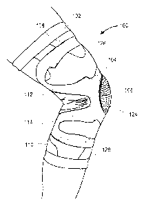
[0026] With reference now to FIG. 1A, one example of a knee brace 100 is
illustrated.
FIG. lA shows a lateral side perspective view of the knee brace 100 on a
wearer's right leg. The
knee brace 100 includes a flexible fabric base or substrate 102 and an
elastomeric member 104.
As shown in FIG. 1A, the elastomeric member 104 includes a curvilinear portion
106 extending
around the lateral side of the patella. As illustrated in FIG. 1A, the
curvilinear portion 106 is
continuous along the length of the knee joint on the lateral side of the
patella. By such a
configuration, the elastomeric member 104 can help to unload in the frontal
plane a medial or
lateral knee compartment, and/or resist extension of the knee on the lateral
side. In some
embodiments, the first elastomeric member 104 or portions thereof (e.g., the
curvilinear portion
106) can extend through an arc of, for example, less than 180 degrees, greater
than 180 degrees,
less than 320 degrees, greater than 320 degrees, between about 180 and 320
degrees, between
about 200 and 300 degrees, or between about 220 and 280 degrees around the
wearer's patella, or
- 5 -
,
within a range defined by any of these numbers. The elastomeric member 104
also includes a
thigh portion 108 and a calf portion 110, which extend generally horizontally
around the thigh and
the calf, respectively. The thigh portion 108 and the calf portion 110 can be
adapted to provide
compression across the bone/tendon junctures above and below the knee joint.
The elastomeric
member 104 also includes a connecting portion 112, which extends upward and
posterior from the
curvilinear portion 106 to connect with a posterior end of the thigh portion
108, and a connecting
portion 114, which extends downward and posterior from the curvilinear portion
106 to connect
with a posterior end of the calf portion 110.
[0027] FIG. 1B is a medial side perspective view of the knee brace
100, and illustrates that
the curvilinear portion 106 is discontinuous about the medial side of the
patella. Such a
discontinuity can facilitate or promote extension of the knee on the medial
side. FIG. 1B also
shows a connecting portion 116, which extends upward from the curvilinear
portion 106 to connect
with an anterior end of the thigh portion 108, and a connecting portion 118,
which extends
downward from the curvilinear portion 106 to connect with an anterior end of
the calf portion 110.
The elastomeric member 104 can include an enlarged portion 120 at or near the
juncture of the
connecting portion 116 with the thigh portion 108. The enlarged portion 120
may be disposed at
or near the region of the vastus medialis oblique (VM0) muscle. In some
embodiments, the brace
100 can include an additional elastomeric member 122 on the medial side of the
patella, spaced
apart from the elastomeric member 104.
[0028] The fabric base 102 can include a fabric, such as a knit or
otherwise stretchy fabric,
to provide compression around the joint. In some embodiments, the fabric base
102 can include a
non-stretchy fabric. Alternatively or in addition, the fabric base 102 can
include regions with one
or more different degrees of stretchiness (e.g., different types of knit;
different moduli of
elasticity), allowing the brace 100 to provide different levels of compression
to different
anatomical regions about the joint. For example, as illustrated in FIGS. IA
and 1B, the fabric base
102 can include a first region 124 having a relatively low elastic modulus,
for example in the
region of the patella, to allow freedom of movement of the patella and avoid
unwanted
compression of the patella against the other structures of the knee joint. The
fabric base 102 can
also include a second region 126 having a relatively higher level of
compression, for example in
the region immediately above and below the patella. The fabric base can also
include a third region
- 6 -
CA 2938568 2018-01-16
CA 02938568 2016-08-02
WO 2015/117132 PCT/US2015/014256
128 having a third and even higher level of compression, for example in the
regions encircling the
thigh and the calf.
[0029] FIG. 2A is a plan view of the outer surface of a left knee brace 200
having all the
same features as the right brace 100, in which like reference numbers reflect
like parts. In FIG.
2A, the details of the regions of varying compression are omitted to better
illustrate the
configuration of the elastomeric members 204 and 222, including, for example,
the curvilinear
portion 206, the thigh portion 208, and the calf portion 210 of the member
204. In FIG. 2A, the
brace 200 is cut open along a seam 230 and laid flat.
[0030] FIG. 2B is a plan view of the outer surface of the knee brace 200,
also cut open
along the seam 230 and laid flat, with the details of the first region 224
(having a first and lower
level of compression), second region 226 (having a second and higher level of
compression), and
third regions 228 (having a middle level of compression, between that of the
first and second
regions 224, 226). Also illustrated in FIG. 2C is a marker 232, which
indicates the front midline
of the brace, directly above the patella, which can be used by a wearer to
assist in proper
positioning of the brace 200.
[0031] FIG. 2C is a cross-sectional view of the knee brace 200, taken along
line 2C-2C of
FIG. 2B. FIG. 2C shows the elastomeric member 204 disposed on outer surface of
the fabric
substrate 202. The section 2C-2C cuts through the second region 226 and the
third region 228.
FIG. 2D is another plan view of the knee brace 200, shown with the elastomeric
material 204
removed to better illustrate the configuration of the first region 224, the
second region 226, and
the third region 228.
[0032] FIG. 2E is a plan view of the inner surface of the knee brace 200,
shown cut open
and laid flat, with the details of the regions of varying compression omitted.
In some embodiments,
as illustrated in FIG. 2E, the knee brace 200 can include on its inner surface
one or more
elastomeric members 234a, 234b. In the embodiment illustrated in FIG. 2E, the
elastomeric
members 234a, 234b are disposed on either side of the patellar region, and are
configured as mirror
images of one another. The elastomeric members 234a, 234b can be disposed so
as to assist the
wearer in properly positioning the brace 200, and also to facilitate proper
patellar tracking. The
elastomeric members 234a, 234b can have a tacky surface, to help the brace 200
stay in place on
the skin when worn. As illustrated in FIG. 2E, in some embodiments, the
elastomeric members
- 7 -
CA 02938568 2016-08-02
WO 2015/117132 PCT/US2015/014256
234a, 234b can include one or more horizontally-extending bars 238 to reduce
the risk of migration
of the brace 200 during wear. In some embodiments, the elastomeric members
234a, 234b can
have a dimpled, striated, or otherwise textured surface, which can assist in
proprioception. The
knee brace can also include one or more elastomeric members 236a, 236b
disposed, respectively,
so as to at least partly encircle the thigh and calf. The elastomeric members
236a, 236b can also
have a tacky surface to help the brace stay in place on the skin when worn.
[0033] The knee braces 100 and 200 illustrated, respectively, in FIGS. 1
and 2A-2E, and
other embodiments incorporating one or more features discussed herein can be
used to help reduce
pain, prevent injury, and promote rehabilitation in patients suffering from
meniscus and/or
cartilage damage, anterior knee pain, tendonitis, osteoarthritis or early
stage osteoarthritis of the
knee joint and knee cap.
[0034] The provision of one or more elastomeric members on a surface of a
flexible fabric
substrate in a support brace can serve to strategically reinforce or add to
any compression provided
by the substrate itself, in a specific design targeted to support certain
joint or limb structures,
facilitate or resist specific movements of the joint, and/or subtly off-load
certain joint structures
(e.g., to increase the space between certain structures in the joint). For
example, in a knee brace
according to an embodiment, one or more elastomeric members can be oriented in
three points of
leverage in the frontal plane, so as to reduce loads on the medial and/or
lateral compartments of
the knee joint. Additionally or alternatively, one or more elastomeric members
can include one or
more circumferential bands either partly or completely surrounding the joint
or limb (e.g.,
extending about or more than halfway around the joint or limb), proximal
and/or distal of the joint.
Such circumferential bands can act as alternative termination points at the
muscle/tendon juncture,
thereby reducing forces on the joint. Additionally or alternatively, one or
more elastomeric
members can include bars or other longitudinally-extending sections crossing
the joint and
positioned so as to assist or resist extension or flexion in desired
anatomical locations. For
example, in one embodiment comprising a knee brace, longitudinally-extending
bars can be
provided on the anterior side of the knee and configured to assist extension
and resist flexion of
the knee, thus easing ambulation efforts. In another embodiment comprising a
knee brace, one or
more elastomeric members can be disposed so as to laterally support the
patella and thereby resist
patellar subluxation.
- 8 -
CA 02938568 2016-08-02
WO 2015/117132 PCT/US2015/014256
[0035] With reference now to FIG. 3, a process 300 for manufacturing a
support brace is
illustrated. At a block 302, a flexible fabric substrate or base layer is
provided. In some
embodiments, the base layer can comprise a comfortable, stretchable, and
breathable material,
such as a fabric made with circular or flat knitting. The base layer can be
adapted to provide both
compression and warmth to the joint or limb when worn. The base layer can
comprise, for
example, a blend of bamboo fiber (e.g. carbonized bamboo), cotton, nylon,
polyester,
polypropylene, wool, and/or spandex. The base layer can be configured with a 2-
way stretch or a
4-way stretch. The base layer can be provided with regions of differing levels
of compression in
any suitable fashion, for example by forming certain regions with a different
type of fabric, a
different type of knitting, or both. Further, the base layer can be provided
with any suitable overall
form to fit the joint or limb for which the brace is designed. For example, in
some embodiments,
such as an embodiment adapted for a knee, calf, forearm, or elbow, the base
layer can have the
form of a tubular sleeve, or a wrap-around configured to closely surround the
joint or limb (e.g.,
with hook-and-loop fasteners, laces, hooks, zippers, or other types of
closures, optionally allowing
an adjustable fit). In some embodiments, the base layer can be produced as an
uninterrupted tube,
which is cut and laid open to facilitate deposition of an elastomeric material
thereon, and then
stitched or otherwise joined back together before being provided to the
wearer.
[0036] At a block 304, a first elastomeric member can be applied to a
surface of the flexible
fabric substrate. The elastomeric member can be applied to an outer surface or
an inner surface of
the substrate. The elastomeric member can be any suitable elastomer, such as,
for example,
polyurethane, polyvinyl chloride, SANTOPRENE thermoplastic vulcanizate,
silicone, or any
other suitable thermoset or thermoplastic elastomer or combination of
elastomers. The elastomer
can be applied to the substrate in any suitable manner, for example using an
adhesive (e.g., a
pressure-sensitive adhesive), melting, stitching, depositing, injection
molding, printing (e.g., silk
screening), welding, being cast in place, or any other method adapted to
securely bond the
elastomer to the substrate. In one example of a welding process, the elastomer
can be cast into the
desired shape and thickness, separately from the base layer, and can then be
welded onto the base
layer. In one example of a printing process, an elastomer such as silicone can
be applied through
a screen and mask in a desired shape and then allowed to set for a suitable
time to release any
trapped air bubbles. The elastomer can then be reapplied, perhaps multiple
times, until the desired
- 9 -
CA 02938568 2016-08-02
WO 2015/117132 PCT/US2015/014256
thickness is achieved. In another example of a printing process, an elastomer
can be applied into a
form or stencil having the desired shape, allowed to set, and then reapplied
(if necessary) to the
desired thickness. In some embodiments, the elastomer can be applied to the
substrate by injection
molding. In such an embodiment, the elastomer can be applied with a constant
thickness, or
alternatively in varying thicknesses, optionally in a single processing step.
Any regions of varying
thickness can be gently graduated or sharply delineated. In embodiments, the
application
technique and type of elastomer can preferably be resistant to delamination or
other degradation
due to wear and tear (e.g. washing and drying, exposure to sweat, sunscreen,
and dirt).
[0037] The elastomeric member(s) can have any suitable thickness. For
example, the
elastomeric member(s) disposed on the outer surface of the base layer can have
a thickness ranging
between about 0.3 mm to 5 mm, or between about 0.5 mm to 5 mm. Also for
example, the
elastomeric member(s) disposed on the inner surface of the base layer can have
a thickness ranging
between about 0.3 mm to 3 mm, or between about 0.5 mm to 3 mm. As mentioned
above, the
thickness of the elastomeric member(s) can be uniform across each elastomeric
member, or can be
variable throughout the pattern of each elastomeric member. For example, in a
knee brace, an
elastomeric member disposed on the outer surface of the base layer can be
thicker in a region
where additional compression is desired, such as in the regions crossing the
thigh and/or calf, and
can be thinner in a region where more flexibility is desired, such as in the
region where the knee
bends. The elastomeric member(s) can be disposed in any suitable pattern
adapted to support the
joint or limb and minimize discomfort associated with any target pain
condition (i.e., osteoarthritis,
anterior knee pain, patellofemoral pain, or another joint pain condition of
the knee or any other
joint or anatomical region of the body).
[0038] FIGURE 4 is a plan view of the outer surface of another example of
a support brace
400 configured in accordance with an embodiment, being adapted to be worn on
the forearm,
shown cut open along two seams 430, 432 and laid flat. In some embodiments,
the brace 400 can
be adapted to help alleviate pain from, for example, golfer's elbow or tennis
elbow. The brace 400
includes a flexible fabric base 402 having a proximal region 420 adapted to be
positioned near the
wearer's elbow and a distal region 422 adapted to be positioned closer to the
wearer's hand. The
brace 400 also includes an elastomeric member 404 with a focal portion 406.
The focal portion
406 can have a V-shaped configuration, as shown in FIG. 4, or a curved shape,
with the apex of
- 10 -
CA 02938568 2016-08-02
WO 2015/117132 PCT/US2015/014256
the V shape or curve configured to be placed at the site of pain and apply
pressure thereto. For
example, in the case of golfer's elbow, the focal portion 406 can be placed at
the inside of the
forearm, and in the case of tennis elbow, the focal portion 406 can be placed
at the outside of the
forearm. The elastomeric member can also include one or more wing portions 408
extending away
from the focal portion 406, in such a way as to divert pain away from the
focal region 406. In
some embodiments, as illustrated in FIG. 4, the wing portions 408 can include
both proximally-
extending portions 410 (extending, for example, in generally the same
direction as the legs of the
V-shape) as well as distally-extending portions 412. The elastomeric member
404 can be
configured to provide differential pressure at different positions around the
forearm and divert
pressure from the site of pain. In some embodiments, the elastomeric member
404 can include
regions of varying thickness, to provide even more variability of compression
at different locations
around the forearm.
[0039] In some embodiments, the fabric base 402 can include regions with
different
degrees of stretchiness (e.g., different types of knit; different moduli of
elasticity), also facilitating
the provision of different levels of compression to different regions about
the forearm. For
example, as illustrated in FIG. 4, the fabric base 402 can include a first
region 424 having a
relatively low elastic modulus, and a second region 426 having a relatively
higher level of
compression.
[0040] FIGURE 5 is a plan view of the outer surface of another example of a
support brace
500 configured in accordance with an embodiment, being adapted to be worn on
the ankle, and
shown cut open along various seams 530, 532, 534 and laid flat. In some
embodiments, the brace
500 can be adapted to support a sprained or injured ankle. In some
embodiments, the brace 500
can be adapted to inhibit or resist inversion and/or eversion of the foot. The
brace 500 includes a
flexible fabric base 502 having a proximal region 520 adapted to be positioned
around the wearer's
lower calf, a distal region 522 adapted to encircle the wearer's forefoot
and/or midfoot, and a heel
region 523 adapted to encircle the wearer's heel. The brace 500 also includes
an elastomeric
member 504, which can comprise a lateral portion 506 and a medial portion 508.
The lateral and
medial portions 506, 508 can be mirror images of one another, as shown in FIG.
5, or can be
configured differently from one another. Further, the lateral and medial
portions 506, 508 can be
separate from one another, as shown in FIG. 5, or can be continuous with or
otherwise connected
-11-
CA 02938568 2016-08-02
WO 2015/117132 PCT/US2015/014256
to one another. In the embodiment illustrated in FIG. 5, the elastomeric
member 504 comprises
two support members 510 configured to extend along the upper part of the
wearer's foot, generally
between the forefoot and/or midfoot and the ankle. As shown in FIG. 5, each of
the support
members 510 includes a generally V-shaped portion, with the apex 512 of the V
shape being
disposed near the forefoot and the legs of the V shape extending back toward
the heel and up
toward the top of the ankle when the support 500 is worn. The apex 512 can
include a filled in,
webbed, or otherwise reinforced portion 514. The elastomeric member 504 can be
configured to
provide differential pressure at different positions around the foot and/or
ankle and support the
foot and ankle. In some embodiments, the elastomeric member 504 can include
regions of varying
thickness, to provide more or less compression at different locations around
the foot and/or ankle,
to allow for a better fit inside a shoe, and/or to interact with features in a
shoe to provide or enhance
stability.
[0041] In some embodiments, the fabric base 502 can include regions with
different
degrees of stretchiness (e.g., different types of knit; different moduli of
elasticity), also facilitating
the provision of different levels of compression to different regions about
the foot and/or ankle.
For example, as illustrated in FIG. 5, the fabric base 502 can include a first
region 524 having a
relatively low elastic modulus, and a second region 526 having a relatively
higher level of
compression.
[0042] FIGURE 6 is a plan view of the outer surface of another example of a
support brace
600 configured in accordance with an embodiment, being adapted to be worn on
the calf, and
shown cut open along two seams 630, 632 and laid flat. In some embodiments,
the brace 600 can
be adapted to support or divert pain in a strained or injured calf, for
example, to divert pain from
shin splints. The brace 600 includes a flexible fabric base 602 having a
proximal region 620
adapted to be positioned around the wearer's upper calf, and a distal region
622 adapted to encircle
the wearer's lower calf. The brace 600 also includes an elastomeric member
604, which can
comprise a lateral portion 606 and a medial portion 608. The lateral and
medial portions 606, 608
can be mirror images of one another, as shown in FIG. 6, or can be configured
differently from
one another. Further, the lateral and medial portions 606, 608 can be
connected to one another, as
shown in FIG. 6, or can be separate from one another. In the embodiment
illustrated in FIG. 6, the
lateral and medial portions 606, 608 each include a cradle portion 610 which
cooperates with the
- 12 -
CA 02938568 2016-08-02
WO 2015/117132 PCT/US2015/014256
other to cradle and support the calf muscle along the length of the calf and
reduce shearing of
muscle tissue. The elastomeric member 604 also includes a support member 612
which is
configured to extend across and support the Achilles tendon when the brace 600
is worn. The
elastomeric member 604 can be configured to provide differential pressure at
different positions
around the calf and support the structures of the calf and/or ankle,
including, for example, the calf
muscle and the Achilles tendon. In some embodiments, the elastomeric member
604 can include
regions of varying thickness, to provide even more variability of compression
at different locations
around the calf and/or ankle. For example, thicker regions can be provided in
the elastomeric
member 704 to provide additional compression and support to maintain position
of the brace when
worn (e.g., to inhibit slippage of the brace down the leg or around the leg).
[0043] In some embodiments, the fabric base 602 can include regions with
different
degrees of stretchiness (e.g., different types of knit; different moduli of
elasticity), also facilitating
the provision of different levels of compression to different regions about
the foot and/or ankle.
For example, as illustrated in FIG. 6, the fabric base 602 can include a first
region 624 having a
relatively low elastic modulus, and a second region 626 having a relatively
higher level of
compression.
[0044] FIGURE 7 is a plan view of the outer surface of another example of a
support brace
700 configured in accordance with an embodiment, being adapted to be worn on
the elbow, and
shown cut open along two seams 730, 732 and laid flat. In some embodiments,
the brace 700 can
be adapted to support or divert pain in a strained or injured arm, for
example, to divert pain from
golfer's elbow or tennis elbow. The brace 700 includes a flexible fabric base
702 having a
proximal region 720 adapted to be positioned around the wearer's upper arm,
and a distal region
722 adapted to encircle the wearer's forearm. The brace 700 also includes an
elastomeric member
704, which can comprise a first portion 706 and a second portion 708, each
extending generally
along the length of the wearer's arm. The first and second portions 706, 708
can be mirror images
of one another, as shown in FIG. 7, or can be configured differently from one
another. Further,
the first and second portions 706, 708 can be separate from one another, as
shown in FIG. 7, or
can be connected to one another. In the embodiment illustrated in FIG. 7, the
first and second
portions 706, 708 can be configured to extend along opposite sides of the
wearer's elbow so as to
assist extension of the elbow joint and so as to provide shock absorption. The
portions 706, 708
- 13 -
CA 02938568 2016-08-02
WO 2015/117132 PCT/US2015/014256
can each include one or more enlarged regions, such as regions 712, 714, which
may be disposed
proximal and/or distal of the elbow. The enlarged regions 712, 714 can be
configured to apply
additional pressure at pain points. The elastomeric member 704 can also
include one or more wing
portions 716, 718 extending away from one or more of the enlarged regions 712,
714 (or from
other regions of the portions 706, 708), in such a way as to divert pain away
from those regions.
The elastomeric member 704 can be configured to provide differential pressure
at different
positions around the arm and support the structures of the arm and/or elbow.
In some
embodiments, the elastomeric member 704 can include regions of varying
thickness, to provide
even more variability of compression at different locations around the arm
and/or elbow.
[0045] In some embodiments, the fabric base 702 can include regions with
different
degrees of stretchiness (e.g., different types of knit; different moduli of
elasticity), also facilitating
the provision of different levels of compression to different regions about
the arm and/or elbow.
For example, as illustrated in FIG. 7. the fabric base 702 can include a first
region 724 having a
relatively low elastic modulus, and a second region 726 having a relatively
higher level of
compression.
[0046] FIGURE 8 is a plan view of the outer surface of yet another example
of a support
brace 800 configured in accordance with an embodiment, being adapted to be
worn on the knee,
and shown cut open along a seam 830 and laid flat. In some embodiments, the
brace 800 can be
adapted to support an injured or otherwise painful knee, for example, to
offload the knee joint and
reduce pain from osteoarthritis. The brace 800 includes a flexible fabric base
802 having a
proximal region 820 adapted to be positioned around the lower thigh, and a
distal region 822
adapted to encircle the wearer's upper calf. The brace 800 also includes an
elastomeric member
804. The elastomeric member 804 includes a curvilinear portion 806 configured
to extend around
the lateral side of the patella when the brace 800 is worn. As illustrated in
FIG. 8, the curvilinear
portion 806 is continuous along the length of the knee joint on the lateral
side of the patella. By
such a configuration, the elastomeric member 804 can help to resist extension
of the knee on the
lateral side. In some embodiments, the elastomeric member 804 or portions
thereof (e.g., the
curvilinear portion 806) can extend through an arc of between about 180 and
320 degrees about
the wearer's patella, or through any other suitable range of degrees. The
elastomeric member 804
also includes a thigh portion 808 which is configured to extend generally
horizontally around a
- 14 -
CA 02938568 2016-08-02
WO 2015/117132 PCT/US2015/014256
portion of the wearer's thigh. The thigh portion 808 can be adapted to provide
compression across
the bone/tendon junctures above the knee joint. The elastomeric member 804 can
also include one
or more wing portions 812, 814 which extend from the curvilinear portion 806
and which are
configured to reinforce the pressure applied by the curvilinear portion 806 to
the lateral side of the
patella. It can be seen in FIG. 8 that the curvilinear portion 806 is
discontinuous about the medial
side of the patella. Such a discontinuity can facilitate or promote extension
of the knee on the
medial side. The elastomeric member 804 can include an enlarged portion 816
disposed below
the patella, so as to apply pressure to the patellar tendon. In some
embodiments, the brace 100 can
include an additional elastomeric member 823 on the medial side of the
patella, spaced apart from
the first elastomeric member 804. In some embodiments, the elastomeric
member(s) 804 and/or
823 can include regions of varying thickness, to provide even more variability
of compression at
different locations around the arm and/or elbow.
[0047] In some embodiments, the fabric base 802 can include regions with
different
degrees of stretchiness (e.g., different types of knit; different moduli of
elasticity), also facilitating
the provision of different levels of compression to different regions about
the arm and/or elbow.
For example, as illustrated in FIG. 8, the fabric base 802 can include a first
region 824 having a
relatively low elastic modulus, and a second region 826 having a relatively
higher level of
compression.
[0048] The various embodiments of support braces and techniques described
above thus
provide a number of ways to provide variable compression to a joint or limb,
in a low-profile and
lightweight brace. Of course, it is to be understood that not necessarily all
such objectives or
advantages may be achieved in accordance with any particular embodiment using
the systems
described herein. Thus, for example, those skilled in the art will recognize
that the systems may
be developed in a manner that achieves or optimizes one advantage or group of
advantages as
taught herein without necessarily achieving other objectives or advantages as
may be taught or
suggested herein.
[0049] Further, although this invention has been disclosed in the context
of certain
preferred embodiments and examples, it will be understood by those skilled in
the art that the
present invention extends beyond the specifically disclosed embodiments to
other alternative
embodiments and/or uses of the invention and obvious modifications and
equivalents thereof. In
- 15 -
CA 02938568 2016-08-02
WO 2015/117132 PCT/US2015/014256
particular, while the present support brace has been described in the context
of a particularly
configured knee brace, the skilled artisan will appreciate, in view of the
present disclosure, that
certain advantages, features and aspects of the support brace may be realized
in a variety of other
applications, many of which have been noted above. For example, while
particularly useful for
knee brace applications, such as the illustrated knee brace application, the
skilled artisan can
readily adopt the principles and advantages described herein to a variety of
other applications,
including wrist braces, elbow braces, shoulder braces, and ankle braces, as
well as to any type of
compression garment, such as compression shirts, vests, sleeves, pants,
shorts, or socks.
[0050] Additionally, it is contemplated that various aspects and features
of the invention
described can be practiced separately, combined together, or substituted for
one another, and that
a variety of combination and subcombinations of the features and aspects can
be made and still
fall within the scope of the invention. Thus, it is intended that the scope of
the present invention
herein disclosed should not be limited by the particular disclosed embodiments
described above,
but should be determined only by a fair reading of the claims that follow.
- 16 -