Note: Descriptions are shown in the official language in which they were submitted.
CA 029 618 2016-08-12
WO 2015/124631 PCT/EP2015/053420
1
MEDICAL DEVICE FOR A CARDIAC VALVE IMPLANT
Field of the Invention
This invention pertains in general to the field of
cardiac valve replacement and repair. More particularly the
invention relates to a medical device for delivering and
retrieving a catheter deliverable cardiac valve implant, a
catheter deliverable cardiac valve implant, and a kit
comprising such delivery and retrieval device and implant,
such as an annuloplasty ring or helix.
Background of the Invention
Diseased mitral and tricuspid valves frequently need
replacement or repair. The mitral and tricuspid valve
leaflets or supporting chordae may degenerate and weaken or
the annulus may dilate leading to valve leak. Mitral and
tricuspid valve replacement and repair are frequently
performed with aid of an annuloplasty ring, used to reduce
the diameter of the annulus, or modify the geometry of the
annulus in any other way, or aid as a generally supporting
structure during the valve replacement or repair procedure.
Such annuloplasty rings or other annuloplasty implants or
cardiac valve implants in general such as replacement
valves, are put into position by various tools.
W02012/027500 discloses an annuloplasty ring that is
ejected out of a catheter by means of a pusher tool. It is
also disclosed that the annuloplasty ring is attached to
the delivery system by a wire that can be pulled to direct
the tip of the implant.
A problem with prior art delivery devices is lack of
steerability or maneuverability of the implant, thereby
increasing the amount of manipulation of the implant both
during the positioning phase and during repositioning to
get the implant in the correct position, which may lead to
a more complicated and time consuming procedure. During
CA 029 618 2016-08-12
WO 2015/124631 PCT/EP2015/053420
2
heart surgery, a premium is placed on reducing the amount
of time used to replace and repair valves as the heart is
frequently arrested and without perfusion.
A problem with prior art devices is also the time
consuming attachment or detachment of the annuloplasty
device, also referred to as the cardiac valve implant, or
simply implant below, to the delivery or retrieval device,
e.g. by using sutures. It would therefore be very useful to
have a medical device for holding the implant to be
positioned that can be quickly attached or detached to such
implant. If repositioning of the cardiac valve implant
becomes necessary it is also critical that the retrieval
device can engage the implant easily and quickly.
A further problem with prior art devices is less-
than-optimal engagement mechanisms between the implant and
the delivery wire that does not provides sufficient
reliability and/or requires exact, i.e. time consuming,
navigation and manipulation before final securement is
achieved.
The above problems may have dire consequences for the
patient and the health care system. Patient risk is
increased.
Hence, an improved medical device for delivering and
retrieving a cardiac valve implant would be advantageous
and in particular allowing for increased maneuverability,
reducing the time of lengthy surgery procedures, cost-
effectiveness, and increased patient safety. Also, a kit
comprising such device and an annuloplasty implant would be
advantageous.
Summary of the Invention
Accordingly, embodiments of the present invention
preferably seeks to mitigate, alleviate or eliminate one or
more deficiencies, disadvantages or issues in the art, such
as the above-identified, singly or in any combination by
providing a device according to the appended patent claims.
CA 029 618 2016-08-12
WO 2015/124631 PCT/EP2015/053420
3
According to a first aspect of the invention a medical
implant delivery and retrieval device is provided
comprising a sheath, a wire having a distal end and being
movable in a lumen of the sheath in a longitudinal
direction of the sheath. The distal end comprises a locking
structure for receiving and interlock with a complementary
mating surface of a medical implant, wherein the locking
structure comprises a first locking surface aligned in a
first radial direction to lock rotational movement of the
implant, when received in the locking structure, around the
longitudinal direction. The wire comprises a pivotable
locking portion having an open and a closed position, the
locking portion has a locking structure with a recess
locking movement of the implant, when received in the
locking structure, in the longitudinal direction, when the
locking portion is in the closed position.
According to a second aspect of the invention a medical
implant delivery and retrieval device is provided
comprising a sheath, a wire having a distal end and being
movable in a lumen of said sheath in a longitudinal
direction of said sheath, said distal end comprising a
locking structure for receiving and interlock with a
complementary mating surface of a medical implant, wherein
said locking structure comprises a locking surface aligned
in a radial direction to lock movement of said implant,
when received in said locking structure, transverse to said
longitudinal direction, wherein said locking surface is
curved in a radial direction.
According to a third aspect of the invention a kit is
provided comprising a medical implant delivery and
retrieval device according to the first aspect of the
invention, and an annuloplasty implant such as an
annuloplasty ring or helix, wherein the annuloplasty
implant comprises a complementary mating surface at an end
portion thereof for interlocking with a locking structure
of the medical implant delivery and retrieval device.
CA 029 618 2016-08-12
WO 2015/124631 PCT/EP2015/053420
4
According to a fourth aspect of the invention an
annuloplasty implant such as an annuloplasty ring or helix
is provided comprising a complementary mating surface at an
end portion thereof for interlocking with a locking
structure of a medical implant delivery and retrieval
device extending along a longitudinal direction. The mating
surface comprises a first locking surface aligned in a
first radial direction to lock rotational movement of the
implant, when received in the locking structure, around the
longitudinal direction. The mating surface comprises a
recess for locking movement of the implant, when received
in the locking structure, in the longitudinal direction.
Further embodiments of the invention are defined in the
dependent claims, wherein features for the second and
subsequent aspects of the invention are as for the first
aspect mutatis mutandis.
Some embodiments of the invention provide for
increased steerability or maneuverability of the implant.
Some embodiments of the invention provide for less
time consuming positioning of an implant at a target site
in the heart.
Some embodiments of the invention provide for less
time consuming attachment and detachment of an implant to a
medical device for efficient positioning and repositioning
of such implant at the annulus.
Some embodiments of the invention provide for
increased accuracy in positioning an implant at the annulus
and thereby reducing the risk of complications.
Some embodiments of the invention also provide for a
reduced risk of damaging the cardiac valve implant during a
repair or replacement procedure.
Some embodiments of the invention provide for better
ability to retrieve and reposition an implant.
It should be emphasized that the term
"comprises/comprising" when used in this specification is
taken to specify the presence of stated features, integers,
steps or components but does not preclude the presence or
CA 029 618 2016-08-12
WO 2015/124631 PCT/EP2015/053420
addition of one or more other features, integers, steps,
components or groups thereof.
Brief Description of the Drawings
5 These and other aspects, features and advantages of
which embodiments of the invention are capable of will be
apparent and elucidated from the following description of
embodiments of the present invention, reference being made
to the accompanying drawings, in which
Fig. 1 is an illustration of a medical device
according to an embodiment of the invention;
Figs. 2a-b are illustrations of a cardiac valve
implant according to embodiments of the invention, to be
positioned with a medical device according in Fig. 1;
Figs. 3a-b are illustrations of the cardiac valve
implant in Fig. 2 held in place with a medical device in
Fig. 1 according to embodiments of the invention;
Figs. 4a-f are illustrations of cross-sectional views
from an axial perspective of the medical device in Figs. 1
and 3 according to an embodiment of the invention;
Fig. 5 is an illustration of a medical device
according to an embodiment of the invention;
Figs. 6a-b are illustrations of a medical device and
implant according to embodiments of the invention;
Figs. 7a-b are illustrations of a medical device and
implant according to embodiments of the invention; and
Fig. 8 are illustrations of a medical device and
implant according to embodiments of the invention.
Description of embodiments
Specific embodiments of the invention will now be
described with reference to the accompanying drawings.
This invention may, however, be embodied in many different
forms and should not be construed as limited to the
embodiments set forth herein; rather, these embodiments are
provided so that this disclosure will be thorough and
CA 02939618 2016-08-12
WO 2015/124631 PCT/EP2015/053420
6
complete, and will fully convey the scope of the invention
to those skilled in the art. The terminology used in the
detailed description of the embodiments illustrated in the
accompanying drawings is not intended to be limiting of the
invention. In the drawings, like numbers refer to like
elements.
The following description focuses on an embodiment of
the present invention applicable to cardiac valve implants
such as annuloplasty rings. However, it will be appreciated
that the invention is not limited to this application but
may be applied to many other annuloplasty implants and
cardiac valve implants including for example replacement
valves, and other medical implantable devices.
Fig. 1 shows a medical implant delivery and retrieval
device 100 comprising a sheath 101, a wire 102 having a
distal end 103 and being movable in a lumen 104 of the
sheath 101 in a longitudinal direction 105 of the sheath.
The distal end 103 comprises a locking structure 107 for
receiving and interlock with a complementary mating surface
108 of a medical implant 200, such as shown in Figs. 2a-b.
The locking structure 107 comprises a first locking surface
109 aligned in a first radial direction (R) (indicated by
dashed arrow in Fig. 1) to lock rotational movement of the
implant 200, when received in the locking structure 107,
around the longitudinal direction 105, i.e. around the
longitudinal axis 105. The locking structure 107 comprises
a second locking surface 110 aligned to face a second
radial direction (R'), different from the first radial
direction (R), to lock movement of the implant 200, when
received in the locking structure 107, transverse to the
longitudinal direction 105. The second locking surface 110
thereby prevents movement of an implant 200 in a transverse
direction, such as in the second radial direction (R')
while the first locking surface 109 hinders the implant
from rotating around axis 105. The implant 200 have a
complementary mating surface 108 comprising first 209 and
second 210 locking surfaces that are positioned opposite,
CA 029 618 2016-08-12
WO 2015/124631 PCT/EP2015/053420
7
i.e. parallel with, first 109 and second 110 locking
surfaces of the device 100. By having two locking surfaces
109, 110, in facing different radial directions, the
implant 200 can be effectively held in place by the device
100 without dislocating when handling of the implant. For
example, torque can effectively be transmitted from the
wire 102 to the implant 200, due to the first locking
surface 109, while the implant 200 can be kept securely in
the central position relative the longitudinal axis 105,
i.e. co-axially positioned relative axis 105 due to the
second locking surface 110 fixating the implant 200 in the
transverse direction relative longitudinal axis 105, such
as in the radial direction. This provides for improved
maneuverability of the implant 200 since it is kept in a
well-defined secure position relative wire 102 without
undesired movement relative the latter. The second locking
surface 110 provides for fixating the position in several
directions transverse to the longitudinal axis 105, i.e.
any transverse direction which has an angle towards the
second locking surface 110, i.e. not parallel to the second
locking surface 110. The second locking surface 110
provides for secure retrieval of the implant 200 if
repositioning or any other adjustments becomes necessary
during the procedure, since the position of the implant in
the radial direction can be controlled, e.g. in the
direction (R') or any other transverse direction with a
vector component in a radial direction to the longitudinal
axis 105. By securing the position in the radial direction,
the implant 200 can be easily withdrawn into sheath 101,
for removing the implant or just keeping the implant in the
longitudinally locked position as described further below.
In this example, if the position of the implant 200 is not
secured in a second radial direction, as provided by the
second locking surface 110, it will be more difficult or
impossible to withdraw the implant 200 into the sheath 101.
It should be noted that the first locking surface 109,
besides from preventing rotational movement of the implant
CA 029 618 2016-08-12
WO 2015/124631 PCT/EP2015/053420
8
200, also stops movement of the implant 200 in a radial
direction, different from the (second) radial direction in
which the second locking surface 110 stops movement. A
radial direction in this disclosure should be construed as
directions having any angle of 0-360 degrees around the
longitudinal axis 105. For example, if the first locking
surface 109 is aligned to face a radial direction (R) of 0
degrees, then the second locking surface may be aligned to
have a radial direction (R') of 90 degrees as exemplified
in Fig. 1.
The locking structure 107 may comprise a recess 106
adapted to interlock with the complementary mating surface
108 to lock longitudinal movement of the implant 200, when
received in the locking structure 107, along the
longitudinal direction 105. Figs. 3a-b shows a side view of
the device 100 when interlocked with the implant 200.
Recess 106 mates with a corresponding protrusion of the
complementary mating surface 108 to fixate the position
along the longitudinal axis 105. This further provides for
improving control of the positioning of the implant 200 in
the device 100 in order to accurately deliver, manipulate,
and possibly retrieve the implant 200 during a procedure.
The recess 106 allows the implant 200 to be drawn into the
sheath 101. The locking structure 107 may thus be arranged
to receive the complementary mating surface 108 when the
locking structure extends outside the sheath 101, and to
interlock with the complementary surface 108 and fixate the
position of the implant 200 relative the locking structure
107 when the locking structure is retracted within the
sheath 101. Hence, when in the withdrawn position, the
sheath 101 restricts movement of the implant 200 in a
radial direction in which the implant was received into the
locking structure 107 in the extended position.
The first (R) and second (R') radial directions may be
substantially perpendicular. This may provide for a more
optimal locking engagement with the implant 200, as the
first and second locking surfaces 109, 110, thereby
CA 029 618 2016-08-12
WO 2015/124631 PCT/EP2015/053420
9
complements each other in restricting movement in any
radial vector component which is not parallel to any of the
surfaces. Even if non-perpendicular locking surfaces 109,
110, would also cover all angles of movement, a
perpendicular arrangement may make the connection between
the locking structure 107 and the complementary mating
surface 108 of the implant 200 easier. In Fig. 3a the
second radial direction (R') is perpendicular to both the
first radial direction (R) and the longitudinal axis 105.
The second locking surface 110 may however also form an
angle relative the longitudinal axis (not shown), e.g. so
that the surface 110 is part of a tapered distal portion of
the locking structure 107. If the distal portion is tapered
towards the implant 200 it may allow for easier guiding of
the implant 200 into the distal portion of the locking
structure 107, while at the same time providing for locking
transverse movement when interlocked as described above.
Alternatively, or in addition, the second radial direction
(R') may have any angle relative the first radial direction
(R). Figs. 4a-f shows a cross-sectional view of the distal
end 103 i.e. perpendicular to the view in Figs. 3a-b. The
wire 102 has a circular profile in the examples. Fig. 4a
illustrates the locking structure in Figs. 1 and 3a-b,
where the first radial direction (R) is perpendicular to
the second radial direction (R'). In Fig. 4a the second
locking surface 110 is angled towards the first radial
direction (R), i.e. forming a distal portion that tapers
towards the first radial direction (R). This may provide
for easier engagement with the implant 200 since the
tapered portion may guide the implant into the final
interlocked position along the first radial direction (R).
The locking structure 107 may be open radially outwards
to receive the complementary mating surface 108 in a radial
direction. As seen in e.g. Fig. 3a, this provides for
convenient interlocking with the implant 200 since the
implant can be approached from the side and guided radially
inwards.
CA 029 618 2016-08-12
WO 2015/124631 PCT/EP2015/053420
The first and/or said second locking surface 109, 110,
may be substantially flat. Hence, while the locking
structure 107 provides for controlled fixation of the
implant 200 the mating surfaces of the locking structure
5 107 and the implant 108 have a minimum of connecting
portions that must be aligned, that also makes interlocking
easier, and particularly of subsequent retrieval of the
implant 200 is necessary.
Alternatively, or in addition, the first and/or said
10 second locking surface 109, 110, may be curved or comprise
a curved portion. The advantage of having a curved surface
is that the implant may be smoothly guided into the correct
position, by tracking the curved surface, as described
further below. This may be advantageous if retrieval of the
implant is required and the surrounding anatomy is moving
due to the beating heart. The curved surface allows a
certain off-set in relation to the final position of the
implant when making first contact with the implant to be
retrieved with the wire 102, which is appreciated due to
the movement of the implant in relation to the wire, both
due to the beating heart and the manipulation of the wire
by the surgeon. The curved surface will guide the implant
into the final secured positioned by a sliding movement.
The curved locking surface is advantageously arranged to
receive the entire portion of the implant that is in
contact with the distal wire 102 in the final locked
position. I.e. avoiding portions of the complementary
locking surfaces of the wire and the implant that are not
contributing to the guiding of the implant to the final
position, will optimize the ability to guide the implant
and also to achieve the most secure and stable position
once the implant has arrived at the final position. The
entire surface of the distal end of the wire that is in
contact with the implant may thus be curved. Prior art
devices may have curved portions of the wire, but are
intended only as an opening through which a neck portion of
the implant may pass, i.e. no complementary locking
CA 029 618 2016-08-12
WO 2015/124631 PCT/EP2015/053420
11
surfaces. Further, the bulk of the implant that is actually
in contact with the wire in the final locked position is
merely resting on a flat surface that has no ability to
guide the implant.
The first or second locking surface may be curved in
the radial direction, e.g. as illustrated in Fig. 4f. This
provides for a centering ability in order to guide the
implant to the correct co-axial position with the wire.
Prior art devices have several sharp protrusions that are
difficult to navigate to. Further, as mentioned above,
since the curved locking surface is advantageously arranged
to receive the entire portion of the implant that is in
contact with the distal wire 102 in the final locked
position, such protrusions are not required for the present
device according to the invention, due to the entire
receiving surface contributing to the guiding, i.e. the
radius of curvature - e.g. in the radial direction - of the
locking surface of the present invention is much larger
than that of the prior art devices having sharp protrusions
each with small radius of curvature, and therefore the
present invention can accommodate a much larger off-set in
relation to the final locked position - when making the
initial contact to the implant with the wire - and still be
able to guide the implant to the correct position.
Fig. 4f illustrates a locking surface that has a
sinusoidal shape, however it may also be possible to have
any concave or convex shape, or a combination thereof. The
implant 200 will in this example have a corresponding
complementary curved shape. The surface of the curved
portion has a normal direction (perpendicular to the
tangent of the curve) that points in varying radial
directions. For example, a first radial direction (R) that
is directed in the vertical plane is indicated in Fig. 4f
at a first point, at the center of the upwardly concave
portion of the sinusoidal shape. The curved surface will
stop rotational movement since it extends in a radially
transverse direction, i.e. with a varying radial distance
CA 029 618 2016-08-12
WO 2015/124631 PCT/EP2015/053420
12
to the longitudinal axis 105, that will lock rotational
movement of an implant 200 having a corresponding surface.
Simultaneously, the curved shape will also stop the implant
200 from sliding in a longitudinally transverse direction
such as along a direction A' indicated in Fig. 4f since the
curved surface also has a normal in a second radial
direction (R'), different from the first radial direction
(R) that will mate with the corresponding surface of the
implant 200 and thereby prevent such transversal movement.
This may provide for easier connection to the implant 200
since the curved surface can stop both rotation and
transverse/radial movement.
As shown in e.g. Fig. 4f the first locking surface 109
may be continuous with the second locking surface 110. The
implant 200 can be easier to capture and retrieve if there
is a smooth path for the implant to follow when being
positioned in the interlocked state. A continuous locking
surface may lock in several directions while allowing an
implant to slide into position. The first and second
locking surfaces 109, 110, may be overlapping in the
longitudinal direction 105. This provides for a simplified
locking structure 108 that may be easier to use and
manufacture. The first and second locking surfaces 109, 110
may thus be provided as a single surface, such as shown in
e.g. Fig. 4f.
The first and second locking surfaces 109, 110, may
also be displaced a distance (D) in relation to each other
in the longitudinal direction 105, as shown in Fig. 1. This
may provide for better stability in the longitudinal
direction 105 since the implant 200 is locked at each
locking surface 109, 110, along the longitudinal direction
105. It may thus require a larger force to accidentally
angle the implant relative the longitudinal direction 105.
The second locking surface 110 may be a recess 111 in
the first locking surface 109, such as shown in Fig. 4c.
The recess 111 will have a surface facing a second radial
direction (R') different from a first radial direction (R).
CA 029 618 2016-08-12
WO 2015/124631 PCT/EP2015/053420
13
Accordingly, the recess 111 will be effective in stopping
rotational movement and also movement transverse to the
longitudinal direction 105, when interlocking with a
corresponding mating surface of the implant 200, i.e. a
protrusion. Alternatively or in addition the second locking
surface 110 may also be protrusion 112 in the first locking
surface 109, as shown in Fig 4d or 4e. In Fig. 4e, the
second locking surface 110 is illustrated as a partly
cylindrical surface, that will stop the implant from moving
in a transverse, e.g. radial direction relative
longitudinal axis 105, i.e. to the left and right in the
figure in the horizontal plane. It should be noted that
movement in the vertical plane is hindered in the downward
direction by the first and/or second locking surface
109,110, and movement in the upward direction in the Figs.
4a-f is stopped by the sheath 101 when the locking
structure 107 is withdrawn into the sheath 101. Returning
to Fig. 4e, the protrusion having a vertical surface facing
the first radial direction (R) will prevent rotational
movement of the implant 200.
The wire 102 may comprise a pivotable locking portion
113 having a closed and an open position, such as
illustrated in Figs. 6a and 6b respectively. The closed
position of the pivotable locking portion 113 locks
movement of the implant 200, when received in the locking
structure 107, in a radial direction. The radial direction
may be the first radial direction (R) as illustrated in
Figs. 6a-b. Since the first locking surface 109 faces the
first radial direction (R), it may be desirable to fixate
the position of the implant 200 in the direction of the
normal to the first locking surface 109. This allows the
implant 200 to be fixated in all direction without having
to retract the locking structure 107 inside the sheath 101.
Further, the pivotable locking portion 113 may grab the
implant 200 if it's going to be retrieved. This may
facilitate engagement of the implant and locking the
implant 200 into the correct position before retracting the
CA 029 618 2016-08-12
WO 2015/124631 PCT/EP2015/053420
14
implant inside the sheath 101, or to get a stable hold of
the implant before it is repositioned at the target site.
The pivotable locking portion 113 may also be arranged to
lock the position in the second radial direction (R') or in
any other radial direction. The pivotable locking portion
113 may be mounted to rotate around a pivoting axis 114 at
the wire 102, and may be engaged with a separate locking
wire (not shown) to be moved between the closed and the
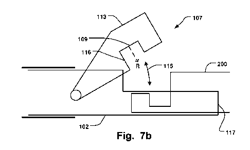
open position with an angle 115. Figs. 7a-b shows an
alternative configuration where the locking portion 113 has
a locking structure 107 with a recess 116 with a first
locking surface 109, and also a second locking surface 110,
that engages with a complementary mating surface 108 of the
implant 200. Hence, instead of having the locking surface
107 at the distal end of the wire, it may be provided at
the pivotable locking portion 113. The distal end of the
wire 102 that receives the implant 200 may have a recess,
such as a partly cylindrical portion 117, that receives a
corresponding cylindrical portion of the implant 200. This
may allow the implant 200 to easily engage with the wire
before locked into position by the pivotable locking
portion 113. The cylindrical portion 117 extends in the
longitudinal direction 105, and it may be shaped to conform
to a corresponding complementary shaped portion of the
implant 200. This provides for a secure fit between the
cylindrical portion 117 and the implant, so while the
implant may slide easily into the cylindrical portion it is
also provided for a secure positioning of the implant on
the distal end of the wire 102. E.g. dislocation of the
implant in the radial directions are prevented by the side
walls of the cylindrical portion. Such side walls are also
illustrated in Fig. 4e. Stabilization and positioning of
the implant at the distal end of the wire is achieved even
if excluding the rectangular element in Fig. 4e. Having
only smooth concave side walls, such as a partly tubular
portion, at the distal end, may facilitate the capturing of
the implant with the wire 102 since the implant may glide
CA 029 618 2016-08-12
WO 2015/124631 PCT/EP2015/053420
smoothly into position. Prior art devices has complicated
interlocking patterns that makes such coupling more
difficult. When the implant has slided into position, the
wire 102 may either be withdrawn for securement into the
5 sheath, and/or a pivoting locking portion 113 may close
over the distal end to fixate the implant. The advantageous
effects provided by having concave surfaces at the distal
end of the wire 102 are thus provided for both types of
interlocking mechanism, i.e. for withdrawal into the sheath
10 as seen in e.g. Fig. 3b, and for the pivoting locking
portion as seen in e.g. 7b. Such concave portion is
illustrated also in Fig. 4f, see locking surface 109, where
non-concentrical positioning of the surface 109 in relation
to the symmetrical (rotational) axis in the cross-section
15 view of the wire 102 is shown. I.e. the rotational axis
extends in the longitudinal direction. Such non-
concentrical arrangement provides for locking of rotational
movement of the implant while maintaining the ease of
implant capture since it can glide smoothly into position
due to the concave or partly circular surface 109. As
further seen in Fig. 4f, the distal end of the wire may
also have a partly circular surface such as a convex
portion, see locking surface 110, which allows smooth
guiding of the implant into the correct position. In the
example in Fig. 4f, the convex surface 110 and concave
surface 109 are in continuous connection with each other,
e.g. a sinusoidal shape as described above. As mentioned,
prior art devices has complicated interlocking patterns
that does not allow such smooth guiding of the implant into
the correct position at the wire 102. When having a
pivotable locking portion 113 it is not necessary to have
non-concentrical concave or convex surface, since the
locking portion 113 may have a locking structure 107 that
stops rotational movement of the implant. The locking
structure 107 can also stop longitudinal movement by having
e.g. a recess 116.
CA 029 618 2016-08-12
WO 2015/124631 PCT/EP2015/053420
16
Fig. 7b shows an arrangement where the second locking
surface 110 has been omitted. The first locking surface 109
of the pivotable locking portion mates with the implant 200
to fixate the position in the longitudinal direction 105,
and to stop rotational movement of the implant. Thus the
locking structure 107 comprises a recess 116, having the
first locking surface 109 which interlocks with the implant
200. Thus the implant 200 can be fixated without having to
interlock with a locking structure of the wire 102, since
the locking structure is provided in the pivoting locking
portion 113. This allows for maintaining a small profile or
cross-section of the delivery device since the wire 102
itself does not need a locking structure, and the implant
can thereby be align co-axially with the wire 102 in the
initial approach, e.g. during a retrieval procedure. Prior
art devices requires the implant to be lifted - i.e. moved
in the radial direction - for positioning into the
interlocking structure of the wire 102. The surrounding
anatomy may not allow such movement. The pivoting locking
portion 113 may be moved only slightly in the radial
direction and still interlock with the implant with the
recess 116. Having the recess 116 in the pivoting locking
portion also allows for more easy advancement of the
implant into the final locked position, since the pivoting
portion exerts a force moving towards the closed position
that pushes the recess 116 over the implant 200. The wire
102 may have a recess, such as a partly cylindrical portion
117, which simultaneously hinders movement of the implant
in a direction transverse to the longitudinal direction
105, e.g. in a direction perpendicular to the longitudinal
direction and the first radial direction (R). This may
allow easy fixation of the implant while maintaining
stability.
The locking surface 109 may be curved in a radial
direction. This allows the implant 200 to slide into the
correct co-axial position with the wire 102, i.e. centering
CA 029 618 2016-08-12
WO 2015/124631
PCT/EP2015/053420
17
is achieved, without the requirement of having other
locking surfaces of the wire in order to achieve centering.
The medical implant delivery and retrieval device 100
may comprise a retrieval element 118 (now shown) connecting
the locking structure 107 and the implant 200 when the
implant is disconnected from the locking structure 107. The
retrieval element 118 may hence serve as a security wire
that can be engaged to retract the implant towards the
locking structure 107 if desired. This may allow for easier
navigation of the implant 200 towards the locking structure
107 and improving the security of the procedure.
Alternatively or in addition, the locking structure 107
may comprise an element 119 (not shown) for attracting the
implant 200 with a force, such as a magnet. Also, the
magnet force may be switchable to an off state that may
ease detachment of the implant 200 from the locking
structure. The implant may also be pushed away from the
magnet with a pusher (not shown) that is movable within a
lumen of the locking structure 107 and exiting and
extending beyond a distal end thereof, in order to again
disengage the implant 200 after being captured with the
magnet. Insertion of such pusher in the locking structure
may disengage the first and/or second locking surfaces from
the implant 200.
Figs. 8a-c illustrates a sheath 101 that is steerable
or shaped to allow for an improved delivery and/or
retrieval angle of the implant 200, so that it can be more
easily and accurately positioned. The sheath 101 may have a
delivery configuration where it extends along a 3-
dimensional path to position its distal end at a defined
angle. Thus, the sheath 101 may assume a desired curve
shape to optimize the positioning of the implant such as an
annuloplasty ring or helix. Fig. 8a show a partly circular
configuration of the sheath in a top-down view, and Fig. 8b
show a side view of the sheath 101. The resulting angle
from which the implant 200 can be delivered is flat and
close to parallel with respect to the valve, which allows
CA 029 618 2016-08-12
WO 2015/124631 PCT/EP2015/053420
18
for accurate positioning and easy insertion of the implant
200 when it exits the sheath 101. The implant 200 may be
shaped from a flexible alloy such as Nitinol, and it is
pre-shaped by heat treatment to assume a desired shape when
exiting the sheath or catheter 101. In addition the implant
200 may comprise an atraumatic tip at its distal end, such
as a partly spherical portion, to avoid damaging the
tissue.
A kit is disclosed according to one embodiment
comprising a medical implant delivery and retrieval device
100, and an annuloplasty implant 200 such as an
annuloplasty ring or helix, wherein the annuloplasty
implant 200 comprises the complementary mating surface 108
at an end portion thereof for interlocking with the locking
structure 107 the medical implant delivery and retrieval
device 100.
An annuloplasty implant 200 is disclosed according to
one embodiment, see Figs. 2a-b, such as an annuloplasty
ring or helix comprising complementary mating surface 108
at an end portion thereof for interlocking with a locking
structure 107 of a medical implant delivery and retrieval
device 100 extending along a longitudinal direction 105.
The mating surface 108 comprises a first locking surface
209 aligned in a first radial direction (R) to lock
rotational movement of the implant 200, when received in
the locking structure 107, around the longitudinal
direction 105. The mating surface 108 comprises a recess
216 for locking movement of the implant, when received in
the locking structure, in the longitudinal direction 105.
This effectively provides control of the implant 200 when
received and interlocked with the delivery device 100.
Prior art implants suffer from less control and less secure
fixation in the delivery device. The recessed surface 216
may comprise the first locking surface 209.
The mating surface 108 may also comprise a second
locking surface 210 aligned to face a second radial
direction (R'), different from the first radial direction
CA 029 618 2016-08-12
WO 2015/124631 PCT/EP2015/053420
19
(R), to lock movement of the implant 200, when received in
the locking structure 107, transverse to the longitudinal
direction 105. Thus, even when not interlocked with the
delivery device 100, e.g. by withdrawing the implant inito
the sheath 101 or closing the pivoting locking portion 113,
such second locking surface will stop movement transverse
to the longitudinal direction, e.g. in the radial
direction. The recessed surface 216 may comprise the second
locking surface 210. Thus locking in the rotational,
longitudinal, and radial directions is provided by having
such mating surface 108, e.g. a recess 216 as described.
Prior art implant provides less secure fixation in all
these directions, or have more complex structures that are
difficult to manufacture. The complementary mating surface
108 may be shaped to mirror any shape such as described
above for the locking portion 107 of the device 100.
The first or second locking surface may be curved in a
radial direction. This provides for the advantageous
effects described above where the implant may be guided
into the correct position in the wire - having the
complementary curved surface - by a sliding motion along
the curved surface. This allows easier capturing and
fixation of the implant 200.
The present invention has been described above with
reference to specific embodiments. However, other
embodiments than the above described are equally possible
within the scope of the invention. The different features
and steps of the invention may be combined in other
combinations than those described. The scope of the
invention is only limited by the appended patent claims.
More generally, those skilled in the art will readily
appreciate that all parameters, dimensions, materials, and
configurations described herein are meant to be exemplary
and that the actual parameters, dimensions, materials,
and/or configurations will depend upon the specific
application or applications for which the teachings of the
present invention is/are used.