Note: Descriptions are shown in the official language in which they were submitted.
CA 02939875 2016-08-24
METHOD AND SYSTEM FOR GENERATING
SULFUR SEEDS IN A MOVING LIQUID
[0001]
STATEMENT REGARDING FEDERALLY SPONSORED RESEARCH OR
DEVELOPMENT
[0002] N/A
REFERENCE TO MICROFICHE APPENDIX
[0003] N/A
BACKGROUND OF THE INVENTION
[0004] 1. Field of the Invention
[00051 This invention relates to the field of converting molten sulfur (or
sulphur) into sulfur
seeds using a moving liquid.
[0006] 2. Description of the Related Art
[0007] Sulfur is an important industrial commodity, most commonly produced
in molten
liquid form as a byproduct from oil and gas refining. Much of the liquid
sulfur is solidified into
various "forms," such as granules, pastilles or prills for ease in
transportation and use. The
various forms are commercially produced by different processes. Granules are
produced by
enlarging "seeds" in a granulating drum; pastilles are formed by laying sulfur
drops onto a
continuous stainless steel belt; and prills are produced by dropping liquid
sulfur into a bath of
cooling water. Whereas pastilles and prills are produced by solidifying single
sulfur droplets, the
production of granules requires a "seed" particle to initiate the enlargement
process.
1
CA 02939875 2016-08-24
=
[0008] A criteria for evaluating sulfur product was established by the
Sulphur Development
Institute of Canada (SUDIC). The shape and particle size distribution of
sulfur forms under the
criteria is generally spherical with the diameter between 2 mm to 6 mm. Sulfur
forms qualify as
"premium product" or "standard product" depending on shape, particle size
distribution,
moisture content, and friability. Sulfur granules and pastilles meet the
premium product
specification in all respects. Wet prills do not meet the premium product
specification with
respect to moisture, and are considered "standard product." A sulfur seed is
understood in the
industry to be a sulfur particle that requires further enlargement to become a
sulfur granule and
obtain maximum commercial value. A sulfur seed is generally considered to be
smaller than 2
mm in diameter.
[0009] The three commercial forming processes also differ in the manner in
which heat is
removed to effect sulfur fusion and cooling of solid particles. In drum
granulation, sulfur is
cooled by transferring heat to the atmosphere inside the drum, the temperature
of which is
moderated by evaporation of water droplets sprayed into the drum. Pastilles
are cooled by
spraying water to the underside of the stainless steel belt, which in turn is
cooled by evaporation
in a cooling tower. Wet prills are cooled by transferring heat to the water
bath which in turn is
cooled by evaporation in a cooling tower.
[00010] U.S. Pat. No. 4,213,924 (Shirley) proposes a method for producing
sulfur granules in a
rotary drum having lifting flights to elevate the seeds that then fall from
the flights as curtains
which are then coated with a spray of liquid sulfur. The discharged product
from the drum is
screened, and seeds that have not been adequately enlarged are returned on
conveyors and either
cooled or heated before being recycled into the input end of the drum. The
'924 Shirley patent
also proposes crushing oversized product discharged from the granulating drum
and recycling
2
CA 02939875 2016-08-24
the crushings to the drum as seed or recycle material. A disadvantage with
crushing is that dust
is created that may become released into the environment. The dust may be
explosive and/or a
health hazard. Also, the crushings are not uniform in size or spherical in
shape.
[00011] In the past, fans have been proposed to force circulation of air
through the falling
curtains for enhanced cooling. A cooler sulfur product tends to be less
friable and less
susceptible to "caking" or "agglomerating" in storage. However, the fans may
become
unbalanced from the sulfur that accumulates on the blades.
[00012] U.S. Pat. No. 4,272,234 (Tse) proposes the production of sulfur seeds
in a granulating
drum by raising the temperature of the rotating bed of sulfur particles for a
short period of time.
The sulfur sprayed on the falling particles in a particular zone of the drum
is proposed to not
immediately solidify but remain soft or plastic on the particles' surface, and
when the particles
are tumbled in the bed, the abrading action of the other particles are
proposed to break off small
pieces of the soft coating having a diameter in the range of about 0.1 to
about 1.0 mm.
[00013] U.S. Pat. No. 4,507,335 (Mathur) proposes the generation of sulfur
seed particles
inside a granulating drum in certain controlled conditions in which liquid
sulfur droplets found in
the outer edges of a thin, flat spray plume solidify into sef.ds prior to
contacting the falling
curtain of solid sulfur particles. U.S. Pat. No. 5,435,945 (De Paoli et al.)
proposes creating sulfur
seeds within a granulating drum by intersecting the molten sulfur spray with a
water spray or by
creating a spray of sulfur droplets that are allowed to solidify in the
atmosphere within the
granulating drum.
[00014] A disadvantage of producing seeds in a granule enlargement drum is
that the
conditions required in the drum for optimum granule production are not the
same conditions
3
CA 02939875 2016-08-24
required for optimum seed production. It generally takes a skilled technician
to monitor and
operate the system.
[00015] U.S. Pat. No. 7,638,076 (Koten) proposes inter alia, passing molten
sulfur through a
nested strainer, a drip tray with a heating channel, an injection conduit for
delivery of a cooled
zone of water to create solid prills, and thereafter moving the prills through
a stationary curved
screen and a vibrating screen.
[00016] A need exists for a method and system to more efficiently create
sulfur seeds to be
used for enlargement into sulfur granules. It would be desirable to control
the size distribution
and production rate of seeds in a manner that corresponds directly to
enlargement requirements
to enable sulfur granules to be produced in a one pass continuous enlargement
process through a
granulating drum at a reasonably high production rate, thereby substantially
eliminating the need
for screening the drum output and recycling undersized product with conveyors
back to the drum
input end. A need also exists to improve the rate at which granules are cooled
in the drum in
order to realize improved product quality and higher production rates.
BRIEF SUMMARY OF THE INVENTION
[00017] Sulfur seeds may be produced by spraying liquid molten sulfur from a
sulfur spray
nozzle into a moving stream of liquid, such as water or other cooling media.
The spray nozzle
may spray the molten sulfur in the same direction as the flow of the moving
liquid. In one
embodiment, some of the sulfur may pass through the liquid and some of the
sulfur may be
entrained in and transported by the stream of liquid. The sulfur droplets that
pass through the
stream of liquid may fall to a cooling tank. In another embodiment, all of the
sulfur remains in
the stream of liquid. The sulfur droplets that are entrained in the stream of
liquid may be carried
by the liquid to the cooling tank. The cooling tank may be a spiral dewaterer
tank with an angled
4
CA 02939875 2016-08-24
bottom and a screw conveyor, in which instance the screw conveyor may
transport the seeds
from the bottom of the tank to a granulating drum used to enlarge the seeds
into sulfur granules.
In one embodiment, a spreading trough may be positioned at a higher elevation
than the cooling
tank to present a wide stream of liquid for the sulfur spray to contact so
that the stream is not in a
container at the time of contact with the sulfur spray. The water may be
supplied to the
spreading trough from the wet scrubber.
[00018] An opening may be made in the bottom surface of the screw conveyor
housing of the
spiral dewaterer tank for liquid to drain from the screw conveyor as it moves
sulfur seeds from
the tank to the granulating drum. In one embodiment, the opening may be
substantially the same
length as the screw conveyor housing. A screen may be disposed across the
opening, and a drain
trough attached to the screw conveyor housing to capture any liquid and solids
that move
through the screen. The screen size may be selected to minimize the number of
solids passing
through it. The drain trough may be angled to assist in transporting its
contents back to the spiral
dewaterer tank. In one embodiment, a pipe may transport the contents of the
drain trough to the
spiral dewaterer tank. In one embodiment, a liquid such as water may be
supplied to the drain
trough to ensure that solids passing through the screen into the trough are
moved to the spiral
dewaterer tank. The water may be supplied from a wash line diverted from the
pipe connecting
the spiral dewaterer tank to the wet scrubber.
BRIEF DESCRIPTION OF THE DRAWINGS
[00019] A better understanding can be obtained with the following detailed
descriptions of the
various disclosed embodiments in the drawings, which are given by way of
illustration only, and
thus are not limiting, and wherein:
CA 02939875 2016-08-24
[00020] FIG. 1 is a schematic view of an exemplary system layout of sulfur
seed generating
spray nozzles with a cooling tank having a screw conveyor disposed with a
sulfur granulating
system, including a granulating drum, and a wet scrubber with cyclone, an air
fan, a belt
conveyor, and air, liquid sulfur, and water lines.
[00021] FIG. 2A is an isometric view of a sulfur seed generating system with a
plurality of
sulfur seed generating nozzles positioned with two sulfur seed header
conduits, a spiral
dewatering cooling tank with its top cover removed, and an internal screw
conveyor.
[00022] FIG. 2B is a plan view of FIG. 2A.
[00023] FIG. 2C is an end view of FIG. 2A.
[00024] FIG. 2D is an elevational view of FIG. 2A.
[00025] FIG. 2E is an isometric view of ten sulfur seed generating nozzles
attached with hoses
to two sulfur seed header conduits.
[00026] FIG, 2F is a detail view of a sulfur seed nozzle of FIG. 2E.
[00027] FIG. 3A is an isometric view of a sulfur seed generating system
disposed with a
granulating drum system.
[00028] FIG. 3B is a plan view of FIG. 3A.
[00029] FIG. 3C is an end view of FIG. 3A.
[00030] FIG. 3D is an elevational view of FIG. 3A.
[00031] FIG. 4A is an isometric view of a portion of the inside of a
granulating drum having a
plurality of sets of segmented lifting flights, some of which are not aligned,
and rib members
attached between the inside surface of the drum and the flights.
[00032] FIG. 4B is similar to FIG. 4A but with one set of segmented lifting
flights adjacent to
the retaining ring at one end of the drum.
6
CA 02939875 2016-08-24
[00033] FIG. 4C is a detail view of a portion of the lifting flights and rib
members in FIG. 4B.
[00034] FIG. 4D is an isometric detail view of three sets of rib members, with
each rib member
set supporting a set of three lifting flights, and one set of lifting flights
parallel with the drum
rotational axis and two of the three sets of lifting flight not parallel with
the drum rotational axis.
[00035] FIG. 5 is a schematic cross-sectional detail view through a
granulating drum of the gap
between the lifting flights and the drum created by the rib members allowing
for more of the
finer grained particles to get needed enlargement from the sulfur spray nozzle
and more of the
coarser grained particles to move through the gap and avoid enlarging sulfur
spray,
[00036] FIG. 6 is an isometric view of a portion of the inside of a
granulating drum having a
plurality of sets of segmented lifting flights some of which are not aligned,
rib members attached
between the inside surface of the drum and the flights, a liquid sulfur header
line (nozzles not
shown), and a water header line with a plurality of water nozzles.
[00037] FIG. 7 is a schematic partial cut away section elevational view of an
alternative
embodiment seed input end of a granulating drum having no lifting flights in
that segment of the
drum and a membrane attached with membrane attachment strips to the inside
surface of the
drum adjacent the retaining ring.
[00038] FIG. 7A is a cross-sectional view of the drum of FIG. 7 showing the
membrane
attached with the drum interior surface with the attachment strips and sulfur
seeds falling into a
seed bed.
[00039] FIG. 8 is an isometric view of a spiral dewaterer cooling tank with a
drain trough
attached with the screw conveyor housing, and a wash line diverted from a pipe
below the screw
conveyor housing and attached at one end of the drain trough.
[00040] FIG. 9 is a plan view of FIG. 8.
7
CA 02939875 2016-08-24
[00041] FIG. 9A is a section view along line 9A-9A of FIG. 9.
[00042] FIG. 9B is a section view along line 9B-9B of FIG. 9.
[00043] FIG. 9C is a section view along line 9C-9C of FIG. 9.
[00044] FIG. 10 is a detail view of detail area 10A of FIG. 8.
[00045] FIG. 11 is an elevational view of FIG. 8.
[00046] FIG. 11A is a sectional view along line 11A-11A of FIG. 11.
[00047] FIG. 12 is a schematic elevational view of a sulfur spray in which
some of the sulfur is
entrained in the liquid flowing from a trough, and some of the sulfur passes
through the liquid.
[00048] FIG. 13 is a schematic elevational view of a sulfur spray in which all
of the sulfur is
entrained in the liquid flowing from a trough.
DETAILED DESCRIPTION OF THE INVENTION
[00049] In FIG. 1, a sulfur seed generating system 5 comprises sulfur seed
generating nozzles
2 (shown in detail in FIGS. 2E and 2F) and a cooling or a forming tank 4. The
cooling tank 4
may be a spiral dewaterer tank with an angled bottom surface and a screw
conveyor or auger 20,
as shown in FIGS. 2A to 2D. Other cooling tank configurations are also
contemplated. As
shown in FIG. 1, liquid sulfur is pumped through a liquid sulfur supply line
14 with a liquid
sulfur pump 22. The liquid sulfur may be diverted from the line 14 to a seed
sulfur line 26 for
delivery to tank 4 through sulfur seed nozzles 2 in spray (or droplet) form.
The cooling tank 4
contains a liquid, such as water, to cool and solidify the molten sulfur
spray. Other liquids,
fluids or coolants are contemplated. Sulfur seeds formed by the interaction of
the sulfur spray
with the liquid settle in the tank 4. The sulfur seeds produced by the system
5 may be spherical
in shape, typically between 0.1 and 2 mm in diameter and require further
enlargement to satisfy
SUDIC size specifications in order to obtain maximum commercial value.
8
CA 02939875 2016-08-24
[00050] Seeds produced in tank 4 may be transported to a granulating drum 6 by
a screw
conveyor or auger 20 or other transport means, such as a conveyor belt or a
drag chain. The
auger 20 may extend above the level of the cooling medium in tank 4 to allow
entrained cooling
medium to drain back to the tank 4. Dewatering of the seeds may minimize the
potential for
seeds to agglomerate together in the drum 6.
[00051] The sulfur line 14 provides sulfur to the drum 6 for enlarging the
sulfur seeds into
granules. An air line 16 provides air to the drum 6, where the air may be
drawn first through
cooling tank cover 76, positioned above tank 4, so as to collect any vapors
that may evolve from
the cooling liquid surface. A water line 18 connects to water pump 24 and a
water filter 40 to
provide water to the drum 6.
[00052] The sulfur supply line 14 may contain measurement devices (27, 28, 32)
and an
ON/OFF valve 30. The measurement devices, sensors or indicators (27, 28, 32)
may measure
temperature, pressure, and/or flow rate. The measurement device 32 located
downstream of the
intersection of the sulfur seed line 26 with the supply line 14 may monitor
for over-pressure and
under-pressure conditions that may cause a system shutdown. For all
measurement devices,
sensors or indicators in FIG. 1, even though a single device may be shown, the
single device may
be representative of more than one device, such as separate devices to measure
temperature,
pressure, flow rate, and/or other conditions. The output of all measurement
devices shown in
FIG. 1 may be interrogated by a control system, such as a computer, processor,
control logic or
microprocessor (not shown). The control system may display the measured value,
modulate the
process control valves and pumps, start up the system, and shut down the
system. The sulfur
supply line 14 and the sulfur seed line 26 may be steam jacketed to keep the
liquid sulfur in the
liquid state for transmission. Steam may be supplied to the jackets by steam
line 34. Condensate
9
CA 02939875 2016-08-24
produced as a result of heat transfer from the steam may be passed to
condensate line 34A via
steam trap 34B of conventional design.
[00053] The sulfur pump 22 insures that seed generating nozzles 2, which are
disposed with
the tank 4 and therefore outside of the drum 6, and sulfur granule enlargement
nozzles (not
shown) inside of the drum 6, are supplied with the needed sulfur flow rate.
The sulfur pump 22
may be a positive displacement gear type pump typically equipped with a
temperature sensor and
a pressure safety valve. Other types of pumps are also contemplated. The
sulfur flow rate to the
drum may be measured by a measuring device 28, and the flow rate in the seed
line 26 may be
the difference between the flow rate measured by the device 27 and the flow
rate measured by
the device 28. The liquid sulfur flow rate to the drum may be controlled by
varying the speed of
the sulfur pump motor using a variable-frequency drive (VFD). The speed may be
set by the
control system in accordance with a flow rate provided by flow measuring
device 27.
[00054] The liquid sulfur pressure in sulfur supply line 14 may be sufficient
so that a pressure
boost by the sulfur pump 22 is not necessary. The pump 22 may be bypassed with
a loop and the
pump 22 turned off by the control system if the sulfur flow rate is met but
the sulfur pump motor
amperes remain below a set value for a given period of time. When the pump 22
is in the OFF
condition, the sulfur flow rate in the seed line 26 may be controlled by a
flow control valve 180
in the seed line 26, and the flow rate to the drum 6 may be controlled by a
flow control valve 181
in the supply line 14 downstream of the intersection with the seed line 26.
The control system
may turn the pump 22 to the ON condition if the sulfur flow rate remains below
one or more pre-
determined set points for a given period of time. With the pump ON, the
control of the sulfur
flow rate to the seed nozzles 2 outside the drum 6 and granule nozzles inside
the drum 6 is
affected by the sulfur pump VFD.
CA 02939875 2016-08-24
[000551 The granulating drum 6 enlarges seeds received from the cooling tank 4
to granules by
building up the seed diameters with numerous coats of solidified liquid
sulfur. The drum 6 may
be sloped at an angle such that the elevation of the discharge end is lower
than the inlet end. The
slope angle may be from 0 to 5 degrees, although other angles are also
contemplated. The flow,
temperature, and pressure of the liquid sulfur to the drum 6 may be monitored
and controlled.
Sulfur pressure may serve as a diagnostic tool. Liquid sulfur temperature and
sulfur granule
temperature may assist the control system to determine the required cooling
water flow rate to
the drum 6 and the corresponding volume of effluent expelled by an exhaust fan
36. The drum 6
may be rotated with a VFD motor so as to allow the operator to vary the
rotational speed of the
drum. Drum torque values may be provided by motor ampere readings to inform
the operator of
any significant change in load. The drum 6 may be instrumented with a speed
switch, which
shuts down the system in the event that drum 6 stops rotating.
[00056] A belt conveyor 10 transports the finished granules to downstream
storage and
handling facilities. The conveyor 10 may be equipped with one or more
measurement devices,
including a motion detector, misalignment detector, and a manual pull cord.
The system may be
shut down based upon signals from any of the belt conveyor measurement
devices. The
temperature of the sulfur granules on the conveyor 10 may be monitored with a
measurement
device 182, which may be an Infrared (ER) instrument. Granule temperature may
be received in
the control system to control the flow rates of water to the drum 6 and
effluent extracted by the
fan 36.
[00057] Water supply line 18 supplies cooling water to the drum 6. Water
delivered to the
drum 6 is sprayed through water nozzles to effect the required cooling by
evaporation. A seed
water line 38 diverts from the supply line 18 and supplies make-up water to
the cooling tank 4,
11
CA 02939875 2016-08-24
The water pump 24 may be a multi-stage centrifugal pump capable of high
discharge pressure.
A recycle loop with a pressure safety valve from the pump discharge to pump
suction may be
utilized to protect the line 18 from overpressure. Other types of pumps are
also contemplated. A
flow measurement device 183 on the pump discharge side may provide the
system's water
requirements. Measurement devices (184, 185) in the line 18 may be used to
measure pressure,
temperature, and/or flow rate, for monitoring and control purposes. Make-up
water to the tank 4
through the water line 38 may be needed to compensate for evaporation of
warmed process water
in a wet scrubber 8 and water exported to the drum 6 with the seeds. Make-up
water may be
modulated by control valve 180A in line 38 in response to the water level
measured by a level
measurement device 187 in the pump section of the cooling tank 4. A
measurement device 188
may be located in the line 26 to monitor pressure and temperature for
diagnostic and/or control
purposes.
[00058] The required water flow to the drum 6 may be determined from several
inputs and
compared to the flow measured by a measurement device 183 on the discharge
side of the water
pump 24 in the water supply line 18. The output of measurement device 183 may
be used by the
control system to control the position of flow valve 186 in the water supply
line 18, confirm
water flow into the drum 6, and as permissive to start the drum 6. The water
flow rate to the
drum 6 may be closely estimated in relationship to the heat released by the
sulfur solidification
process. The computed water flow rate may be subject to error since the water
introduced into
the drum 6 as entrained moisture in the seed stream may not be measured. In
this case, the flow
valve in the line 18 may be manually trimmed if needed.
[00059] Air supplied through the air supply line 16 is drawn into the drum 6
and becomes
progressively hotter and more humid as it migrates through the drum as a
result of heat transfer
12
CA 02939875 2016-08-24
from granules to water spray which results in the production of water vapor.
The wet scrubber 8
of conventional design and operation captures and removes sulfur dust and
sulfur mist present in
the drum effluent moving out of the drum in the drum effluent line 58. Process
water in the
cooling tank 4 flowing over a cooling tank weir 46 may be pumped through the
wet scrubber line
12 with a wet scrubber supply pump 44 to the wet scrubber 8. A measurement
device 48 in the
line 12 may provide temperature, pressure, and/or flow rate measurements.
[00060] The process water with sulfur dust particles collected in cyclone 64
of wet scrubber 8
flows through a line 52 to a cooling tank supply pump 42, which pumps the
slurry back to the
cooling tank 4 where the dust particles become entrained in seed sulfur
droplets. The sulfur dust
in the cooling tank may be captured by contact with molten sulfur droplets
streaming down the
cooling liquid column such that the dust particles become incorporated into
the droplet, thereby
being converted to a substantially spherical seed. It is also contemplated
that the dust particles
may be settled out in some other tank or system. The balance between water to
and from the wet
scrubber 8 may be maintained by controlling the water level at the bottom of
the cyclone 64. A
measurement device 50 in a cyclone slurry output line 52 may monitor water
level. The water
level may be maintained by VFD control of the pump 42 motor speed. A
measurement device
54 in the line 52 on the discharge side of the pump 42 may measure temperature
and pressure. It
is anticipated that all of the heat transferred to the fluid in tank 4 as a
result of seed generation
may be rejected by evaporation in the wet scrubber such that the temperature
of the fluid in the
line 52 may be cooler than the temperature of the fluid in the line 12. The
line 52 may include a
heat exchanger (not shown) to further cool the fluid returning to the tank 4.
Heat absorbed by
the heat exchanger may be rejected using a suitable cooling device such as a
cooling tower or
aerial cooler.
13
CA 02939875 2016-08-24
[000611 A measurement device 56 in the drum effluent line 58 to the wet
scrubber 8 may
measure temperature. A measurement device 60 in a cyclone air output line 62
connected with
the fan 36 may measure temperature. The differential pressure across the wet
scrubber 8 may
also be measured. The fan 36 moves air through the system at a flow rate
controlled by a VFD
on the fan motor. The fan 36 may be protected by a vibration switch. The
effluent flow rate
required to maintain a desired sulfur product temperature may depend on
several parameters,
including ambient dry bulb temperature, ambient humidity, liquid sulfur
temperature, liquid
sulfur flow rate, sulfur product temperature, water flow rate and temperature,
and drum effluent
temperature and humidity. The humidity of the drum effluent may be derived
from the several
inputs because direct measurement may be unreliable at high temperature and
humidity
conditions, The fan 36 VFD may be manually trimmed to accommodate any
uncertainty in the
determined humidity.
[00062] Turning to FIGS, 2A to 2D, the seed generating system 5 is shown with
the cooling
tank 4. In this embodiment, the cooling tank 4 is a spiral dewaterer tank with
a screw conveyor
or auger 20. Spiral dewaterer tanks are available from Metso Corporation of
Helsinki, Finland,
among others. The tank 4 is disposed on tank support structure or skid 80A for
ease of
transportation to a different location and set up for quick operation. The
tank 4 is filled with a
cooling liquid 72, such as water. Other liquids, fluids and coolants are
contemplated. The liquid
72 temperature may be 65 C to 75 C, or approximately 70 C, although other
temperatures are
also contemplated. The height of weir 46 in the tank 4 may be adjusted to
change the depth of
the water column for the seed droplets to solidify in the tank. It is
contemplated that water will
overflow the weir 46 since the water may be continuously circulated.
14
CA 02939875 2016-08-24
[00063] The tank cover or hood 76 (shown in FIG. 3A) positioned above tank 4
has been
removed. First and second sulfur seed header conduits (70A, 70B) disposed with
the tank 4 are
in fluid communication with sulfur seed spraying nozzles 2, and are shown in
detail in FIGS. 2E
and 2F. Returning to FIGS. 2A to 2D, it is contemplated that the tank 4 may be
deep enough so
that sulfur seed droplets may be solidified by the time the droplets reach the
floor of the tank.
The tank depth may be 96 inches (2.4 m) at the deep end and 31 inches (.8 m)
at the shallow end;
the tank width may be 78 inches (2 m) at the wide end and 24 inches (.6 m) at
the narrow end,
although other depths and widths are also contemplated.
[00064] The cyclone slurry output line 52 shown in FIG. 1 transports a water
and sulfur
particle mixture from the drum 6 and the wet scrubber 8 into the tank 4 as
shown in FIGS. 2A,
2B and 2D. The tank 4 may be used both to generate seeds from sulfur delivered
by the nozzles
2 and to remove sulfur dust received from the line 52 in the manner described
above with FIG. 1.
It is also contemplated that the sulfur dust removal process and the seed
generation process may
be separated. The liquid flow in the tank 4 is generally from the right side
to the left side as the
tank is viewed in FIGS. 2A and 2D. In FIG. 2B, the sulfur seed nozzles 2 are
attached in fluid
communication with a first sulfur seed header conduit 70A and a second sulfur
seed header
conduit 70B. In Fla 2D, the sulfur seed supply line 26 from FIG. 1 is shown
for connection
with the second header conduit 70B.
[00065] In FIG. 2E, ten sulfur seed nozzles 2 are attached with the first
header 70A and the
second header 70B with ten sulfur seed tubings or hoses 74. The tubing 74 may
be insulated.
Other attachment means are also contemplated, including attaching the nozzles
2 directly with
the header conduits (70A, 70B). A header input conduit 71 may be in fluid
communication with
the sulfur seed supply line 26 of FIG. 1. The nozzles 2 may be aimed or
disposed at a certain
CA 02939875 2016-08-24
angle from horizontal toward the liquid 72 in the tank 4, such as 45 down
from horizontal,
although other angles are also contemplated. The nozzles 2 may be rotated to
different angles.
The nozzles 2 may be disposed at a certain distance from the liquid 72 in the
tank 4. The
distance may be 12 inches (30.5 cm), although other distances are also
contemplated. The
nozzles may be spaced approximately 12.4 inches (314 mm) apart, although other
spacing is also
contemplated. The nozzles 2 may be conventional fluid spray nozzles such as
are available from
Spraying Systems Company of Carol Stream, Illinois, among others.
[00066] The orifice size and spray angle of the nozzles 2 may be
selected/configured for
optimum seed production. It is contemplated that the equivalent diameter of
the orifice may be
4.4 mm, although other equivalent orifice diameters are contemplated, such as
from 1.4 to 5.8
mm. It is contemplated that the spray angle may be 65 , although other angles
are contemplated
from 25 to 90 . The contemplated nozzle 2 may correspond with a 6550 flat fan
nozzle
available from Spraying Systems Company, although other types and
manufacturers are also
contemplated. The sulfur pressure under which nozzle 2 operates will vary in
accordance with
the number, type, and size of nozzles 2 that are required to realize the
required flow rate. A
spray pressure from 5 psi to 200 psi is contemplated.
[00067] The nozzles 2 may be selected with a flat fan spray (tapered, even,
and/or deflected), a
conical spray including hollow cone and/or full cone, and/or a deflected
spray, although other
spray types are also contemplated. Different spray tips may be installed to
change the spray
pattern and droplet size distribution. It is also contemplated that the
nozzles 2 attached with the
headers (70A, 70B) may each have different orifices, spray angles, angles
aimed from horizontal,
and/or other characteristics. Although ten sulfur seed nozzles 2 are shown in
FIG. 2E, it is
16
CA 02939875 2016-08-24
contemplated that other numbers of the nozzles 2 may be used, such as from
four to sixteen
nozzles 2.
[00068] The pressure and/or flow rate of the sulfur moving through the sulfur
seed nozzles
may be adjusted by the control system to increase or decrease the particle
size and amount of
sulfur seeds produced. The nozzle orifice size, spray angle, and/or other
characteristics may also
be selected to change the seed size and production rate.
[00069] It is contemplated that ten (10) sulfur seed nozzles such as shown in
FIG. 2E may be
used with 314 mm (12.4 inch) spacing and a 45 angle downward from horizontal.
Other
configurations and distances are also contemplated. Each seed nozzle may have
a flat fan pattern
with a 65 spray angle, a 4.4 mm equivalent orifice, and 45 psi liquid sulfur
pressure. Other
configurations, pressures and sizes are also contemplated. A model 6550 nozzle
from Spraying
Systems Company gives a contemplated spray angle and size. It is contemplated
that seeds
produced with a 6550 flat fan nozzle oriented at 45 downward from horizontal
and liquid sulfur
pressure of 15 psi may produce about 97.7% of seeds by weight that are smaller
than 2.36 mm,
and about 98.4% of seeds by weight that are larger than 0.3 mm, so that 96% of
the seeds may be
between 2.36 and 0.3 mm. It is contemplated that at 45 psi liquid sulfur
pressure, the size
distribution may shift to 98% of seeds by weight less than 2.0 mm and 98% of
seeds by weight
larger than 0.15 mm, so that 96% of seeds may be between 2.0 and 0.15 mm.
Other distributions
and sizes are also contemplated.
[00070] The sulfur nozzles used to enlarge seed in the drum may produce a flat
spray pattern
having a tapered or even edge. A plurality of sulfur nozzles may be used on a
spray header or
manifold such that the spray pattern of adjacent nozzles may overlap in order
to provide uniform
coverage across the falling curtains in the axial direction. The spray pattern
may have spray
17
CA 02939875 2016-08-24
angles from 15 to 1100. A nozzle producing a flat even spray pattern may
provide a uniform
spatial density of droplets throughout the entire flat spay pattern. It may
have spray angles from
15 to 110 . The thin rectangular spray pattern may provide uniform coverage
with minimal
overlap between adjacent nozzles. A flat even spray pattern may be produced by
a deflected
type nozzle. The spray pattern of medium sized drops is formed by liquid
flowing from a round
orifice over the deflector surface. The spray angles may be from 15 to 150 .
The nozzle may
have a large free passage design though the round orifice that reduces
clogging. The narrow
spray angles provide higher impact, while the wide angle versions produce a
lower impact.
[00071] In FIGS. 3A to 3D, the cooling tank 4 is in fluid communication with
the granulating
drum 6; the wet scrubber 8 and the cyclone 64 are in fluid communication with
the drum 6; and
the fan 36 is in fluid communication with the cyclone 64. The tank 4 is
disposed on the tank
support structure Or skid 80A, drum 6 is disposed on the drum support
structure or skid 80B, and
the cyclone 64 and the wet scrubber 8 are disposed on the cyclone support
structure or skid 80C,
all for ease of transportation to a different location or quick set up for
operation. A cooling tank
top cover 76 is disposed with the tank 4 so that the sulfur seed nozzles 2 are
not visible. The
screw conveyor 20 may move seeds to the drum 6 having a first plenum or breach
78A and a
second plenum or breach 78B. The drum effluent line 58 in FIG. I moves the
air, water vapor
and sulfur particle mixture to the wet scrubber 8, which captures and removes
the sulfur dust to
the fluid exiting the wet scrubber in line 52. The drum 6 may have a diameter
of approximately
feet (3 m) and a length of approximately 30 feet (9 m), although other sizes
are contemplated.
Sulfur granules discharged from drum 6 drop onto belt conveyor 10 shown in
FIGS. 3A, 3B and
3C (conveyor 10 is not labeled in FIGs 3A, 3B, or 3C).
18
CA 02939875 2016-08-24
[00072] Turning to FIG. 4A, the drum 6 is shown without the first plenum 78A.
A first
retaining ring 82 minimizes spillage from the drum 6, and another similar
second retaining ring
may be positioned at the opposite end of the drum 6. The first retaining ring
82 may have a
height of five inches (12.7 cm), although other heights are contemplated. A
first set of lifting
flights 88 is disposed with an interior surface 98 of the drum 6. First set
rib members (84A, 84B)
may be disposed between the first flights 88 and the drum interior surface 98.
There may be a
plurality of segmented sets of the first set rib members (84A, 84B) disposed
around the interior
surface 98 of the drum 6. The sets of rib members (84A, 84B) are segmented in
that each set is
shorter than the circumference of the interior surface of the drum. Each rib
member (84A, 84B)
may have a curved length equaling approximately 1/4 of the inside
circumference of the drum 6,
such as covering 900 of the 360 circumference. However, other lengths are
also contemplated.
The segmentation of the rib members allows for easy assembly, maintenance and
transport.
[000731 Each segmented set of rib members (84A, 84B) may support a plurality
of flights 88,
such as from 1 to 20, with 14 being the preferred amount. The rib member 84A
may be attached
with the drum 6 at least at two locations, such as at a first connection point
85A and a second
connection point 85B. As shown in FIG. 4A, the rib member 84A is preferably
attached with
drum 6 at four locations: first connection point 85A, second connection point
85B, third
connection point 85C, and a fourth connection point (hidden from view by
flight 88A). It is
contemplated that each connection point, such as first connection point 85A
and second
connection point 85B, may have a bolt welded to the interior surface of drum 6
extending
radially into the drum 6 and passing through a hole in the rib member (84A,
84B). A nut may be
used to secure the rib member (84A, MB) with the drum at each connection point
(85A, 85B).
19
CA 02939875 2016-08-24
[00074] FIGS. 4B and 4C show the connection points of the rib members with the
drum
interior surface. FIG. 4B is similar to FIG. 4A except that first flights 88
of a drum 6A are
positioned with one end adjacent to a first retaining ring 82A. The retaining
rings (82, 82A) may
have heights at least as large as the heights of the flights (88, 90, 92, 94,
96). A rib member 84A
in FIG. 4B is connected with the interior surface of the drum 6A at a first
connection point
(hidden from view behind flight 88B), a second connection point 85B, a third
connection point
85C, and a fourth connection point 85D. As shown in FIG. 4C, the second
connection point 85B
of rib member MA has two holes 85B1 and two holes 85B2. Bolts (not shown) are
centered on
reference line 87 through holes 85B2. Bolts (not shown) are also positioned
through the two
holes 93B in the rib member 84B and the two holes 95A in a rib member 86A
along a reference
line 87. The first set of lifting flights 88 is not in alignment with the
second set of lifting flights
90. The two holes 95B in the rib member 86A allow for alignment of the first
set of lifting
flights 88 with the second set of lifting flights 90 by moving rib member 86A
so that holes 95B
are positioned along the reference line 87 and bolts are positioned through
the holes 95B rather
than the holes 95A.
[000751 A third connection point 85C of rib member 84A has two holes 85C1 and
two holes
85C2. Bolts (not shown) are centered on reference line 89 through holes 85C2.
Bolts (not
shown) are also positioned through the two holes 83B in rib member 84B and the
two holes 91A
in rib member 86A along reference line 89. Again, the two holes 91B in rib
member 86A allow
for alignment of the first set of lifting flights 88 with the second set of
lifting flights 90 by
moving rib member 86A so that holes 9111 are positioned along reference line
89 and bolts are
positioned through holes 91B rather than holes 91A. All other rib members and
flights may be
similarly disposed with the drum 6.
CA 02939875 2016-08-24
[00076] As shown in FIG. 4C, each rib member (84A, 84B, 864) may have two
pairs of holes
at each connection point, such as two holes 85B1 and two holes 85B2 at second
connection point
85B of rib member 84A, to allow for the staggering of adjacent flight
segments. The rib
members may have a pair of matching holes spaced apart by half the distance
between adjacent
flights of a flight segment. A staggered configuration may be effected by
attaching the ribs to
the bolts on the drum wall using alternating hole pairs, e.g. the top pair for
the first set of flights,
the bottom pair for the second set of flights, the top pair for the third set
of flights, and so on. A
non-staggered alignment may be obtained by aligning the top pair (or bottom
pair) of holes in all
the flight segments with the bolts. There may be more than one bolt and nut
used at each
connection point, such as connection points 85A and 85B. Other connections are
also
contemplated.
[000771 Returning to FIG. 4A, it is contemplated that flights 88 may be welded
to the rib
members (844, 84B), although other connections are also contemplated. It is
also contemplated
that there may be no rib members (844, 84B), and that the first flights 88 may
be attached
directly with the interior surface 98 of the drum 6. As can now be understood,
the rib members
(844, 84B) allow for ease in handling and/or replacement of the first flights
88. As shown with
FIG. 5 and discussed therewith in detail below, the thickness of rib members
(84A, 848)
advantageously provides a gap between the first flights 88 and the surface 98
through which
larger seeds and/or granules may move as the drum 6 rotates.
[00078] In FIG. 4A, a second set of lifting flights 90 is also disposed with
the interior surface
98 of the drum 6. Second set rib members (86A, 86B) may be disposed between
the second
flights 90 and the drum 6 in a similar configuration as the first set rib
members (84A, 84B). It is
also contemplated that there may be no rib members (86A, 86B), and that second
flights 90 may
21
CA 02939875 2016-08-24
be attached directly with the interior surface 98 of the drum 6. A third set
of flights 92, a fourth
set of flights 94, and a fifth set of flights 96 are also shown attached with
respective rib members
in a similar manner. The flights (88, 90, 92, 94, 96) are not continuous
through the length of the
drum 6 but are segmented as they are all shorter than the length of the drum
6.
[00079] The flights (88, 90, 92, 94, 96) may be 4 feet (1.216 m) in length,
although other
lengths are also contemplated. The flights (88, 90, 92, 94, 96) are not
aligned, but are offset
from each other. It is also contemplated that one or more sets of flights (88,
90, 92, 94, 96) may
be aligned, such as the first flights 88, the third flights 92, and all other
odd number of flights.
The even numbers of sets of flights may also be in alignment. Although the
sets of rib members,
such as the first rib members (84A, 84B) and the second rib members (86A,
86B), may have the
same thickness, it is also contemplated that different sets of rib members may
have different
thicknesses. The non-aligned or staggered flights may advantageously increase
air circulation
and cooling in the drum.
[00080] The flights (88, 90, 92, 94, 96) are disposed with the drum interior
surface 98 on lines
parallel with the longitudinal or rotational axis of the drum 6, such as the
first flight 88 attached
with the first rib members (84A, 84B) at respective locations (104A, 104B).
It is also
contemplated that one or more sets of flights (88, 90, 92, 94, 96) may be
disposed with the drum
interior surface 98 on lines not parallel with the longitudinal axis of the
drum 6, such as shown in
FIG. 4D.
[00081] In FIG. 4D, first set of rib members (206A, 206B), second set of rib
members (208A,
208B), and third set of rib members (210A, 210B) are attached with an interior
surface 212 of a
granulation enlargement drum, such as drum 6. First set of flights 222 are
attached with first set
of rib members (206A, 206B), second set of flights 224 are attached with
second set of rib
22
CA 02939875 2016-08-24
members (208A, 208B), and third set of flights 226 are attached with third set
of rib members
(210A, 210B). Only three sets of rib members and flights are shown in FIG. 4D
for clarity,
although more sets of rib members and flights are contemplated. In relative
relation to each
other, first flights 222 are positioned closest toward the input end of the
drum, and third flights
226 are positioned closest to the output end of the drum.
[00082] Reference lines (200A, 200B, 200C) are shown for illustrative purposes
and are
parallel with the drum rotational axis. First set of flights 222 are attached
with first set of rib
members (206A, 206B) on lines coincident with or parallel to reference lines
(200A, 200B,
200C), Second set of flights 224 are attached with second set of rib members
(208A, 208B) on
lines not parallel with reference lines (200A, 200B, 200C). Using second
flight 224A with
second flight centerline 216 for illustrative purposes, second flight
centerline 216 is disposed at
angle 214 from reference line 200B. Likewise, the other second flights 224 may
be disposed at
angle 214 from their nearest reference line (200A, 200B, 200C). Similarly,
third set of flights
226 are attached with third set of rib members (210A, 210B) on lines not
parallel with reference
lines (200A, 200B, 200C). Using third flight 226A with third flight centerline
218 for
illustrative purposes, third flight centerline 218 is disposed at angle 220
from reference line
200B. it is contemplated that angle 220 may be greater than angle 214.
Although only three sets
of flights are shown, it is contemplated that there may be more sets of
flights, with each
successive flight from the input end toward the output end of the drum
disposed at an larger
angle from the reference line. As can now be understood, a lifting flight may
be disposed in a
plane that only intersects the drum axis at one location.
[00083] The angled flight attachment lines may allow for progressively faster
movement of the
particles from the input end of the drum 6 to the output end utilizing a screw
type action. The
23
CA 02939875 2016-08-24
angled flight attachment lines may change the distance that sulfur granules
advance down the
drum for each drum rotation. It is contemplated that the angle of attachment
may get
progressively larger from the input end to the output end of the drum 6. This
may maintain a
constant height of the granule bed in the drum in the axial direction, without
which the depth of
seeds and granules in the bed at the bottom of the drum sometimes may
significantly exceed the
height of the flights. This condition prevents the flights from lifting the
majority of the seeds and
granules into the airspace where they may be effectively cooled.
[00084] The angled or screwed flights may advantageously increase the exposure
of hot seeds
and granules to the cooling atmosphere by minimizing the height of the bed of
seeds and
granules in the drum. The cooler product tends to be less friable and less
susceptible to "caking"
or "agglomerating" in storage. The spiral flights move more granule volume as
more volume is
produced. This keeps the bed depth at a constant height (slightly above the
flights) all the way
down the drum. The result is that virtually all granules are kept in
circulation to the curtains
where they are effectively cooled. Without volumetric acceleration, the extra
volume may
simply increase the bed depth so more of the bed simply tumbles without being
lifted, making
cooling less effective.
[00085] Returning to FIG. 4A, height 100 of first flights 88 may be the same
as or different
from height 102 of second flights 90 or any other of the flights. it is
contemplated that the flights
(88, 90, 92, 94, 96) may be 5 inches (12.7 cm) in height, although other
heights are also
contemplated. It is also contemplated that one or more of the flight sets may
have angled heights
so that their height is not constant across the length of the flights. The
angled flights may allow
progressively larger volume of particles to be lifted into the airspace from
the input end of the
drum 6 to the output end. As the bulk volume of granules increases in the
axial direction, the
24
CA 02939875 2016-08-24
deeper flights volume is lifted into the airspace at that particular point
where it can be cooled. It
is contemplated that the angles may get progressively larger from the input
end to the output end
of the drum. It is also contemplated that a flight may not be contained in a
single plane, such as
being curved or bent. It is contemplated that all of the described embodiments
of the flights and
rib members may be used in any combination or permutation. By varying the
configuration of
the flights, it is possible to maintain a level amount of sulfur granules
along the bottom of the
drum 6 as the drum 6 rotates.
[00086] Turning to FIG. 5, the lifting flights (99, 99A, 99B, 99C, 99D) are
spaced apart from
the drum 6 by the thickness of rib members (not shown), providing a gap 132
between the flights
(99, 99A, 99B, 99C, 99D) and the drum 6 interior surface. It is contemplated
that the rib
thickness may be in a range from 1/4 inch (.64 cm) to 2 inches (5.1 cm),
although other
thicknesses and gaps 132 are also contemplated. As the drum 6 rotates
clockwise, the flights
(99, 99A, 99B, 99C, 99D) elevate seeds and granules from a bed 134. There may
be a natural
stratification of granules in the bed 134 through a thickness 146, with course
particles found near
the exposed surface and grading to fines adjacent to the drum interior
surface. It is contemplated
that the flight 99A first fills with coarse granules sliding down the bed 134.
The course granules
may slide to the approaching flight 99A, which then fills with progressively
smaller granules and
seeds. The height 130 of flights (99, 99A, 9913, 99C, 99D) limits their
lifting capability to an
outer boundary line 144. Pre-emergent flight 99B may have coarse grains near
the gap 132, and
finer grains near the outer boundary line 144.
[00087] The flight 99C may have coarse grains 148 fall though the gap 132 as
the flight 99C
begins to discharge so that a majority of coarse grains 148 may not be exposed
to a sulfur spray
142 from a spray nozzle 140 attached with a sulfur header conduit 138 in the
drum 6. This is
CA 02939875 2016-08-24
advantageous because it allows for more efficient enlargement of the smaller
particles, which
need more enlargement than the larger particles. Finer grained particles 150
from the flight 99D
may discharge into falling curtains 136 toward the sulfur spray nozzle 140 and
are the most
likely to be sprayed. Fine particles such as a particle 152 may be in the
falling curtain 136
closest to the spray nozzle 140. The falling curtain 136 closest to the nozzle
140 may consist
mostly of small grains.
[00088] Turning to FIG. 6, a drum sulfur header line 120 and a drum water line
116 are
disposed in the interior of the granulating drum 6B. The sulfur supply line 14
from FIG. 1 may
be in fluid communication with the drum sulfur header line 120, and the water
supply line 18
from FIG. 1 may be in fluid communication with the drum water line 116. The
drum sulfur line
120 has a plurality of sulfur spray nozzles for spraying and enlarging sulfur
seeds that are not
shown. The spray nozzles may be spaced approximately 8 inches (20 cm) apart,
although other
spacing is also contemplated. It is contemplated that the drum sulfur spray
nozzles may be
aimed substantially horizontally, although other angles are also contemplated.
[00089] The drum sulfur line 120 may have the capability to rotate to allow
spray to be
directed downward, upward, or horizontally into the falling curtains. This in
particular facilitates
the use of a deflected spray sulfur nozzle. The drum sulfur line 120 may be
steam jacketed. The
drum sulfur line 120 may be disposed approximately 1 foot (30.5 cm) from the
nearest location
of the drum 6B interior surface, although other positions are also
contemplated. The drum sulfur
line 120 may be 30 feet (9.1 m) long inside the 30 foot long drum 6B with
additional one foot
extensions outside of the drum at both ends to attach to a supporting
structure. Other dimensions
are also contemplated.
26
CA 02939875 2016-08-24
[00090] The drum water line has a plurality of water spray nozzles 118. It is
contemplated that
the water nozzles 118 may be angled downward, such as 450 from horizontal,
although other
angles are also contemplated. Similar to FIGS. 4A and 4C, exemplary sets of
flights 122 and rib
members (110A, 110B) are shown, with the flights 122 having lengths 126 and
heights 124, and
a rib member 110A attached with the drum 6B at a first connection point 112A,
a second
connection point 112B, a third connection point 112C, and a fourth connection
point 112D.
[00091] In FIG. 7, an alternative embodiment is shown for a seed input end 176
of a
granulating drum 160. Flights 162 may begin at a distance 164 from the seed
input end 176 of
the drum 160, so that there may be no flights in distance 164. The distance
164 may be
approximately two feet (.6 m) to four feet (1.2 in), although other distances
are also
contemplated. A retaining ring 166 may be at a drum end 176. As best shown in
FIG. 7A, a
membrane 170 may be attached to the interior surface of drum 160 in the
distance 164 with
membrane attachment strips 168. The membrane 170 may be a flexible silicone
based
membrane, although other types of materials for the membrane 170 are also
contemplated. The
membrane attachment strips may be conventional dimensional steel such as
channel stock. It is
contemplated that wet seeds may enter the drum end 176 and be in a tumbling
seed bed 172, in
which seeds may be held together by moisture. As the drum 160 rotates,
dislodged seed clumps
may fall, such as in curtains 174, to the bed 172. As can now be understood,
the membrane 170
allows for seeds that may have a tendency to clump from moisture to
potentially be separated
and dried before being elevated by lifting flights 162. Normal airflow without
water spray
through this zone may dry out the seeds before entering the normal flighted
section of the drum
160.
27
CA 02939875 2016-08-24
[00092] The embodiments described above may allow control of the size
distribution and
production rate of seeds, produced outside the granulating drum, that enable a
one pass
enlargement cycle through the drum (no seed recycle) at a high production rate
(1500 tonne per
day or more). This capability may eliminate the need for an output screen and
underside recycle
conveyor (lower capex and opex). The system may provide for an increase in
unit production
rate and improved product quality enabled by improved cooling of granules
(i.e. enhanced
exposure of granules to the sweep air that itself is kept cool by water
evaporation). This may be
achieved by non-aligned or staggered lifting flights. This may provide for a
more tortuous path
for airflow around the falling curtains.
[00093] A drum revolutions per minute (RPM) may be selected such that the
falling curtains
fill approximately 75% or more of the granulating drum volume. Flights
attached with rib
members or attached directly to the drum on lines not parallel with the drum
rotational axis
provide for a "screwed flights" design to move the bed to the discharge end at
a progressively
faster rate, corresponding to sulfur mass introduced as spray, so that the
amount of granules
tumbling in the bed and not being cooled may be kept to a minimum. A
substantially constant
product temperature may be maintained in respect to changes in key operating
variables, such as
sulfur production rate, the temperature of the liquid sulfur and the sulfur
product, and ambient
temperature and humidity, among others. This may be achieved by adjusting the
airflow rate
through the drum by varying the speed of the fan. The fan speed may be
determined by the
control system or processor using inputs from the various instruments.
[00094] There may be improved control of the particle size distribution of the
product by
incorporating a gap between the flights and the drum shell that allows
preferential spraying of
the finer granules and seeds as a result of discharging the coarse granules in
the curtains most
28
CA 02939875 2016-08-24
distal from the sulfur spray nozzles. Since the seed particles may be wet,
there is a possibility
that the seeds may stick to and clog up lifting flights that originate at the
seed input end of the
drum. This may be mitigated by removing the flights in the first two to four
feet of the drum and
installing a flexible membrane around the inside wall of the drum. The
membrane, which may
be non-rubber, may flex as it rotates to the top of the drum, allowing the
clumps to fall back into
the bed. Normal airflow without water spray through this zone may dry out the
seeds before
entering the normal flighted section of the drum.
[00095] The system shown schematically in FIG. I may be disposed on support
structures or
skids for ease of construction or transportation, such as support structures
(80A, 80B, 80C) in
FIGS. 2A-2D, 3A-3D, and 4A-4B. The system may substantially eliminate the
conveyors and
other structures of the prior art extending from the output end of the drum to
the input end of the
drum that are required for the recycling of undersized sulfur particles back
through the drum.
Further, the modular nature of the system allows for easy set up and
operation. Also, the
production of sulfur seeds externally to the drum 6 may allow for the use of
lower pressures in
the drum 6, and better optimization of granule production. The separation of
the seed production
from the granule production also may allow for better optimization of seed
production.
Although the preferred use of the method and system is for sulfur (or
sulphur), it is also
contemplated that the method and system, and any of the embodiments and
components, may be
used for converting other molten liquids to solid seeds or granules, such as
asphalt. Although the
exemplary embodiment of the method and system passes the molten sulfur through
water, other
fluids or cooling medium besides water, as known in the art, but novel when
used herein, are
contemplated and may be used.
29
CA 02939875 2016-08-24
[00096] Turning to FIGS. 8-11A, the seed generating system 300 is similar to
the seed
generating system 5 in FIGS. 2A to 2D, with the differences described in
detail below. Seed
generating system 300 may be used in the system of FIG. 1. Similar to the seed
generating
system 5 of FIGS. 2A-2D, seed generating system 300 of FIGS. 8-11A has a
cooling tank 304, a
screw conveyor or auger 314, and a screw conveyor housing 302. The screw
conveyor housing
302 extends outwardly from the cooling tank 304 and encloses a portion of the
screw conveyor
314. Unlike the seed generating system 5 of FIGS. 2A-2D, the seed generating
system 300 of
FIGS. 8-11A has an opening on the bottom side of the screw conveyor housing
302 that is
covered with screen 316, which is best shown in FIG. 11A. Screen 316 may be a
wedge-wire
screen with 1 mm openings, although other screens and openings are also
contemplated. Drain
trough 306 is attached with screw conveyor housing 302 around the opening.
[00097] The opening may run substantially the same distance as the drain
trough 306, although
other opening sizes are also contemplated. As can now be understood, the water
or other liquid
that is transported by the auger 314 with the sulfur seeds through the screw
conveyor housing
302 may drain through the screen 316 to the drain trough 306. The drain trough
306 is on an
incline since it follows the screw conveyor housing 302. A drain trough pipe
308 may be
attached at one end of the drain trough 306 to transport the water and solids
back to the cooling
tank 304. As shown in FIG. 8, drain trough pipe 308 may enter tank 304 at tank
port 318. The
draining of the water from the screw conveyor housing 302 through the screen
316 assists in
controlling the moisture content of the sulfur seeds transported by the auger
314.
[00098] Some solid sulfur particles may fall through the screen 316 to the
drain trough 306.
As best shown in FIG. 10, wash line 310 may divert water or other liquid from
line 312 and
transport it to the high end 320 of the drain trough 306. Line 312 may be the
wet scrubber line
CA 02939875 2016-08-24
12 shown in FIG. 1 that runs from the seed generating system (5, 300) to the
wet scrubber 8.
Other sources of water are also contemplated. The water or other liquid from
wash line 310
enters the upper end 320 of the drain trough 306 and flushes or washes the
solid particles that
have fallen through the screen 316 to the cooling tank 304.
[00099] A valve 358 may be included in line 310 to regulate the flow rate of
water. Sight glass
360 may be included in line 308 to monitor the flow rate of water back to tank
304. The amount
of water that may drain from seed depends on the distance travelled over
screen 316, which
distance may be controlled by varying the water level in tank 304 as effected
by adjusting the
elevation of weir 362. As seen in FIG. ii, a short drain distance corresponds
to a high level in
the tank (level A) while a long drain distance corresponds to a low level in
the tank (level B). It
is contemplated that level A may be 2 feet higher than level B. A plurality of
drain ports may be
located in drain trough 306 for use in conjunction with the water level in
tank 304. As seen in
FIG. 11, the greatest drain distance is obtained using drain port 364 in
conjunction with the
lowest level B of water in tank 304. Similarly, the least drain distance is
obtained when drain
port 366 may be connected to line 308 in conjunction with the highest level A
of water in tank
304.
[000100] Turning to FIG. 12, a sulfur seed nozzle 332 is positioned over
moving stream of
liquid or water 336 in a tank (not shown). The sulfur spray seed nozzle 332
can be of a flat fan
type but other spray nozzles with different spray patterns are contemplated.
The water 342 may
be transported from the wet scrubber through pipe 344 (which in one embodiment
is extends
below the water level), which may be the cyclone slurry output line 52 in FIG.
1. Other sources
of water or liquid are also contemplated. The water 342 from the wet scrubber
flows from pipe
344 into spreader pan 368 having an inclined chute 330, which allows a wide
stream of water
31
CA 02939875 2016-08-24
336 to be presented to the sulfur spray 334. The spreader pan 368 allows for
the even flow across
the width of the flume. The sulfur spray 334 is in the same direction as the
flow of the stream of
water 336. In this embodiment, some of the sulfur passes through the water,
and sulfur droplets
340 are created, which may fall to a cooling tank, such as the cooling tank
304 in FIG. 8. Some
of the sulfur is entrained in the water and sulfur droplets 338 are created,
which may be
transported by the stream of water 336 to a cooling tank, such as the cooling
tank 304 in FIG. 8.
Sulfur droplets 338 in the moving stream 336 may be finer than sulfur droplets
340. It is
contemplated that spray nozzle 332 may be anywhere from 3 inches (7.6 cm) to 2
feet (80.3 cm)
from the nearest location of the stream of liquid 336, with the preferred
distance around 1 foot
(30.5 cm). Other distances are also contemplated. The spray nozzle 332 may
spray at a
relatively shallow angle from horizontal. The chute 330 may be approximately 1
foot (30.5 cm)
wide, although other distances are also contemplated. For all embodiments, it
is also
contemplated that the spray nozzle may be below the stream of liquid, and that
the sulfur spray
may not be in the same direction as the flow of moving liquid. However, it may
be advantageous
to spray the sulfur in the same direction as the moving liquid to minimize the
relative velocity
between the two.
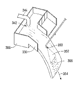
[0001011 In FIG. 13, sulfur seed nozzle 350 is positioned over moving stream
of liquid or water
354. The water is transported from the wet scrubber through pipe 344, which
may be the
cyclone slurry output line 52 in FIG. 1. Other sources of water or liquid are
also contemplated.
The water 342 from the wet scrubber flows from pipe 344 into spreader pan 368
having an
inclined chute 330, which allows a wide stream of water 354 to be presented to
the sulfur spray
352. The sulfur spray 352 is in the same direction as the flow of the stream
of water 354. Unlike
in FIG. 12, in FIG. 13 all of the sulfur is entrained in the water, and sulfur
droplets 356 are
32
CA 02939875 2016-08-24
created, which may be transported by the stream of water 354 to a cooling
tank, such as the
cooling tank 304 in FIG. 8. Sulfur droplets 356 may be courser than the sulfur
droplets 338
entrained in the moving stream of water in FIG. 12. It is contemplated that
spray nozzle 350
may be anywhere from 3 inches (7.6 cm) to 2 feet (80.3 cm) from the nearest
location of the
stream of liquid 354, with the preferred distance around 1 foot (30.5 cm),
although other
distances are also contemplated. The spray nozzle 350 may spray at a
relatively shallow angle
from horizontal. The spreading trough 330 may be approximately 1 foot (30.5
cm) wide,
although other distances are also contemplated.
[000102] The foregoing disclosure and description of the invention are
illustrative and
explanatory thereof, and various changes in the details of the illustrated
apparatus and system,
and the construction and the method of operation may be made without departing
from the spirit
of the invention.
33