Note: Descriptions are shown in the official language in which they were submitted.
CA 02940085 2016-11-25
Docket: 11253-035 1
METHOD AND DEVICE FOR DETERMINING NAVIGATION DATA
Field of the invention:
The invention concerns a method for determining navigation data and a device
for
carrying out the method.
Background of the invention:
For navigation, in particular in aviation, increased demands are made on the
integrity
of track and positional angle information. This integrity is achieved by
reliable yaw
attitude reference systems and by redundant equipment such as multiple
installations
and emergency instruments.
To increase the accuracy hybrid systems are used that couple an inertial
navigation
platform and a satellite navigation system via a Kalman filter.
In addition to the accuracy of a specific parameter also its integrity has an
important
role in aviation. The integrity of the satellite navigation system alone is,
however, not
sufficient for all applications in aviation. This is in particular then the
case, if the
satellite navigation system influences the determination of position. If the
satellite
navigation system is also used in the redundant equipment, the integrity of
the
satellite navigation system determines substantially the integrity of the
whole
navigation system. The integrity of satellite navigation system is, however,
limited from
below. Hence, also the integrity of hybrid systems in a single or in multiple
implementations is limited.
Integrity denotes the probability according to which the error of a
measurement value,
such as e.g. the position, does not exceed a predetermined threshold.
For example, integrity may be determined by the maximally allowed error rate
during a
reference unit. Here, an erroneous measurement is a measurement, whose
measurement values deviates by more than a tolerance value from a reference
value.
The reference value may be the actual value or a value of the measured
quantity based
on previous measurements.
CA 02940085 2016-11-25
Docket: 11253-035 2
The reference unit in respect to which the error rate is determined may be
each unit
that is suitable for measurements of position or track changes. The reference
unit may
for example be a time unit, such as e.g. minutes, hours or days. Then, the
error rate is
determined by dividing the number of transgressions of the predetermined error
bound
(i.e. the number of erroneous measurements) by the selected time unit. The
error rate
is then indicated for example as the number of errors per hour. The reference
unit may
also be a length unit, such as e.g. meter, kilometer, nautical miles. The
integrity may
then for example be indicated as the number of errors (i.e. number of
transgressions of
the error bound) per nautical mile. The reference unit may also be an
indication of
degrees with respect to latitude and longitude on Earth's surface, such as
e.g. degree,
angular minute, or arc second. The integrity is then for example indicated as
number
of errors per angular minute.
A high integrity is achieved, if the number of erroneous measurements is very
low, for
example if erroneous measurements occur considerably more rarely than once in
thousand years (this corresponds to an integrity of approximately 10-7/hour).
For aviation and seafaring in particular the integrity of the role angle and
the pitch
angle (positional or orientation angles) as well as of the track angle is of
importance,
as these describe the orientation of watercrafts or aircrafts in space. If,
for example
the role angle of a watercraft becomes too large, it is endangered to
overturn. In
addition, in driving a curve, the radius of the driven (or aviated) curve may
be
estimated from the role angle. If the pitch angle is determined wrongly during
approach for landing of an aircraft, a safe landing is endangered.
An erroneous measurement of track or positional angles is present, if a
measurement
value of one of the angles deviates by more than a tolerance value from the
respective
reference value. The reference value may be the actual value of the angle or a
value of
the angle that is interpolated from data measured so far.
According to the position and maneuver of the vehicle the requirements to the
frequency of occurrence of allowed erroneous measurements and hence to the
integrity
may be differently severe. For a watercraft in quiet water on open sea, an
aircraft
connected firmly to the watercraft or standing on earth, or an aircraft that
is in great
height the requirements to the integrity are lower than for a watercraft in
heavy sea or
close to coast or for an aircraft during approach for landing.
CA 02940085 2016-11-25
Docket: 11253-035 3
Typical tolerance values in aviation are 4 to 5 for deviating of positional
angle
measurement values from the respective reference values and of about 10 for
deviations of track angle measurement values from the respective reference
values.
Using these tolerance values navigation systems of aircrafts with high
integrity should
ensure that the probability for transgression of the tolerance values for the
positional
angle measurements is smaller than 10-9 per hour (i.e. less than 10-9
erroneous
positional angle measurements per hour or about one erroneous measurement in
100.000 years) or for track angle measurements less than 10-7 per hour (i.e.
less than
10-7 erroneous track angle measurements per hour or about one erroneous
measurement in 1.000 years).
In order to guarantee a high accuracy of the angular measurements in
conventional
systems, hybrid navigation platforms are used that couple inertial navigation
platforms
with satellite navigation systems via Kalman filters.
Measurement values of the inertial navigation platform are generated in this
process
by acceleration sensors and rotation rate sensors. As rotation rate sensors
mechanic
gyroscopes, fiber optic rotation rate sensors, laser gyroscopes or micro
electromechanical rotation rate sensors may be used. Nowadays often
micromechanical
sensors are used as acceleration sensors. Here, during system initialization
reference
is made to Earth's rotation rate and the direction of gravitation, in
particular for
determining the track angle. The horizontal component of Earth's rotation rate
that
has to be determined for this process becomes, however, smaller with
increasing
geographical latitude, i.e. towards the pols track determination becomes
increasingly
less accurate.
The satellite navigation system may be the global position system (GPS) or any
other
satellite navigation system, such as Galileo, GLONASS or Compass. The
satellite
navigation system determines the position and the velocity of vehicles by
means of
distance measurements to at least four satellites in earth orbit. In "weakly
coupled
systems" the position and velocity provided by the satellite navigation system
is used
in a Kalman filter as measurement. In "strongly coupled systems", in contrast,
the
distances and their changes to the single satellites are used as measurements
in the
Kalman filter. This allows recognizing and excluding of erroneous satellites
and an
estimation of error rates and the integrity by exclusion of redundant
measurements.
However, this requires in comparison with a "weakly coupled system" a
considerably
larger amount of data processing.
CA 02940085 2016-11-25
Docket: 11253-035 4
Inertial navigation platforms and the satellite navigation systems transmit
the
measurement values determined by them to the Kalman filter. Based on the
previously
obtained satellite measurement values, the Kalman filter estimates corrections
for the
present orientation/position of the vehicle. To achieve this effect the hybrid
navigation
platform must, however, be exposed to accelerated movements.
Due to this coupling of an absolute positioning system as constituted by the
satellite
navigation system with a relative system as constituted by an inertial
navigation
platform, quickly converging and very accurate orientation and position data
can be
generated by means of the Kalman filter for dynamical movements of the vehicle
continued over a certain time, which exceed the accuracy of purely inertial
navigation
platforms considerably. In particular, a very accurate determination of the
track angle
is possible, as the position data do not depend on the geographical latitude,
on which
the navigation platform is located, in contrast to the measurement values of
purely
inertial navigation platforms.
However, in this process it is problematic that the obtained highly precise
orientation,
track, and position accuracies have only the integrity of the satellite
navigation system
and that for example the orientation/positional angles cannot be determined
with the
sufficiently high integrity for aviation of 10-9/h. With 10-4 per hour
(without additional
integrity surveillance on ground, such as e.g. SVAS ("Satellite Based
Augmentation
System"), GBAS ("Ground Based Augmentation System")) and with 10-7 per hour
(with
ground surveillance) the integrity of weakly coupled hybrid systems is below
the
requirements of aviation.
It is, hence, not possible to initialize hybrid navigation platforms by means
of weakly
coupled satellite navigation system data such that a high integrity can be
achieved, as
the insufficiently high integrity of the satellite navigation system is
transferred into the
hybrid navigation platform. Hence, for an aircraft starting e.g. from a
watercraft no
sufficiently high integrity can be obtained by a conventional hybrid
navigation
platform.
Summary of the invention;
The invention is therefore concerned with the object to indicate a method and
a device
for determining navigation data that ensure a high integrity.
CA 02940085 2016-11-25
Docket: 11253-035 5
The invention is directed to a method for determining navigation data. The
method
comprises the steps of:
determining positional angle measurement values with a first navigation
device;
and
initializing a second navigation device with the positional angle measurement
values determined by the first navigation device.
In this process, the first navigation device and the second navigation device
are
provided from a sensor unit with rotation rate and acceleration measurement
values
for the determining of the positional angle measurement values. Further, in
the first
navigation device erroneous measurements of positional angle measurement
values
occur with a probability that is smaller than a predetermined positional angle
error
= rate. In contrast, in the second navigation device erroneous measurements
of the
positional angle measurement values occur with a probability that is larger
than the
predetermined positional angle error rate. Here, an erroneous measurement of
the
positional angle measurement value is present, if one of the determined
positional
angle measurement values deviates by more than a predetermined positional
angle
tolerance value from a respective positional angle reference value.
The invention is directed to a device for determining navigation data. The
device
comprises a first navigation device for determining positional angle
measurement
values, a second navigation device for determining positional angle
measurement
values, and a sensor unit that provides rotation rate and acceleration
measurement
values for determining the positional angle measurement values to the first
navigation
device and the second navigation device. In this process, the second
navigation device
is initialized with positional angle measurement values determined by the
first
navigation device. Further, in the first navigation device erroneous
measurements of
positional angle measurement values occur with a probability that is smaller
than a
predetermined positional angle error rate. In contrast, in the second
navigation device
erroneous measurements of positional angle measurement values occur with a
probability that is larger than the predetermined positional angle error rate.
Here, an
erroneous measurement of the positional angle measurement value is present, if
one of
the determined positional angle measurement values deviates by more than a
predetermined positional angle tolerance value from a respective positional
angle
reference value.
CA 02940085 2016-11-25
Docket: 11253-035 6
This guarantees that the second navigation device is initialized with
measurement
values that satisfy higher integrity requirements than the second navigation
device can
=
provide itself.
Therefore, the high integrity of the first navigation device can be combined
with
advantageous characteristics (e.g. high measurement accuracy of position and
orientation data) of the second navigation device. For example, the first
navigation
device may be an inertial navigation platform as described above and the
second
navigation device may be a hybrid navigation platform as described above.
In a scenario according to the invention a helicopter is located on a ship.
The aim is to
provide after an initialization and orientation phase of the hybrid system
track and
positional angles with the required accuracy and integrity.
The proposed system comprises thereto a purely inertial navigation platform
and a
hybrid navigation platform.
First, the inertial system carries out a classical gyro compass alignment. To
this end,
the system should only carry out such accelerated movements that are mean
value free
if considered over the period of alignment. The inertial navigation platform
is then
initialized after completion of the dynamic gyro compass alignment with the
track/positional angles obtained in this process. Because of the movement, the
achieved accuracy is, however, not sufficient for navigation operation and the
system
is operated as track/position reference.
Alternatively, the heading alignment (i.e. the track determination) may also
be carried
out by means of a magnetic sensor (i.e. a compass) or by means of input of the
present
heading by the pilot. The accuracy and integrity of the heading initialized by
this
alternative method must be in compliance with the integrity requirements of
the
application. However, because of the limited accuracy, this method is also not
suitable
to allow operation of the system in navigation mode.
The hybrid navigation platform is initialized by the track/positional angles
of the
inertial navigation platform. This ensures that the linear error model
implemented in
the Kalman filter can be used.
CA 02940085 2016-11-25
Docket: 11253-035 7
At the time of initializing accuracy and integrity of hybrid and inertial
platform are the
same.
By means of accelerated movements occurring after the initialization or
alignment due
to ship maneuvers or aircraft movements the Kalman filter is able to estimate
the
system errors by using the GPS measurements and to apply them as corrections.
This
leads to a quick improvement of the accuracy of track/positional angles of the
hybrid
platform. If the estimated accuracies reach specified values, the
track/positional
angles of the hybrid platform are set valid. Now highly precise
track/positional angles
are available, that have, however, due to using the GPS measurements a
decreased
integrity with respect to the initial state and that are hence not in
compliance with the
requirements.
To use the high precisions obtained in the hybrid system for the inertial
navigation
platform with high integrity the following approach is taken:
If the differences between hybrid and inertial track/positional angles are not
larger
than the allowed thresholds that are fixed for the integrity, the integrity at
the time of
comparing can be considered as ensured for the hybrid track/positional angles
influenced by the GPS measurements. In this case, the inertial platform can be
re-
initialized with the highly precise track/positional angles of the hybrid
platform. After
this re-initialization highly precise track/positional angles are available to
the inertial
platform with the required integrity and the system can be transferred from
operation
as track/position reference system to the navigation mode.
Brief description of the drawings:
Based on embodiments the invention will be explained in what follows with
reference
to the figures. It show
FIG. 1A and 1B schematically navigation of watercrafts and aircrafts,
FIG. 2A to 2C schematically the positional and track angles of a
vehicle,
FIG. 3 schematically a device for determining navigation data according to
an embodiment,
CA 02940085 2016-11-25
Docket: 11253-035 8
FIG. 4 a schematic process flow of a method for
determining navigation
data according to an embodiment.
Elements or element groups corresponding to each other are designated in the
figures
by the same reference signs.
FIG. 1A shows a watercraft 110. The watercraft 110 may be any ship of any
size. The
watercraft may for example be a sport boat, a fisher boat, a yacht, a cruiser,
a frigate,
a battle ship or an aircraft carrier.
Detailed description of preferred embodiments:
= On the watercraft 110 an aircraft 120 may be present. The aircraft 120
may for
example be a helicopter, an airplane or a rocket. According to an embodiment
the
watercraft 110 is a yacht and the aircraft 120 a helicopter.
The watercraft 110 navigates along a course 130. For determining the course
130 the
watercraft comprises various navigation systems. By means of these navigation
systems the watercraft 110 can determine its position (longitude and
latitude), its
orientation with respect to the North Pole (track angle), its inclination to
the side (role
angle), its frontward inclination (pitch angle) and its velocity.
The aircraft 120 is firmly connected to the watercraft 110 and has therefore
the same
position data. As navigation on water has to satisfy other requirements than
navigation in air it is, however, necessary to provide the aircraft 120 during
take-off
from the watercraft 110 with navigation data that satisfy the requirements of
aviation.
FIG. 1B shows the aircraft 120 on its course 130 after it has been separated
from the
watercraft 110. The aircraft 120 may according to a different embodiment also
have
started from a different place than the watercraft 110, for example from
ground or
from the surface of the water. According to an embodiment the aircraft 120 is
an
airplane.
The navigation data that are available to the aircraft 120 typically have to
comply with
strict requirements. In particular, the integrity of measurements that are
carried out
by navigation systems on board of the aircraft 120 must be sufficiently high
in order to
CA 02940085 2016-11-25
Docket: 11253-035 9
avoid an erroneous determination of position/ orientation and hence dangerous
situations.
As explained above for aviation and seafaring in particular the integrity of
role angle
and pitch angle (positional angles) as well as of the track angle is of
importance, as
these describe the orientation of the aircraft or watercraft 110, 120 in
space.
Positional angles and track angles are illustrated in FIGs. 2A to 2C.
FIG. 2A illustrates the role angle r by means of a watercraft 210. The role
angle r is a
positional angle and describes the rotation of the transverse axis of the
watercraft with
respect to the horizontal. The role angle has positive sign, if the starboard
side (right,
if viewed in front direction) of the watercraft is inclined towards the water.
Here, the
rotation axis, which is perpendicular to the plane in which the role angle is
measured,
is inclined by the pitch angle with respect to the horizontal plane, i.e. the
role angle
measurement plane is not a vertical plane. The role angle r may be different
from zero
by maneuvers of the watercraft 210, due to uneven loads on the watercraft 210
or due
to movement of the water 250.
FIG. 2B illustrates as further positional angle the pitch angle n. The pitch
angle
describes the rotation of the longitudinal axis of the watercraft with respect
to the
horizontal. The measurement plane of the pitch angle is the plane that
contains the
longitudinal axis of the watercraft and is perpendicular to the horizontal
plane, it is
hence a vertical plane. If the longitudinal axis of the watercraft viewed in
front
direction is above the horizontal plane, a positive pitch angle will be
obtained. As for
the role angle r the pitch angle n may be different from zero due to maneuvers
of the
watercraft 210, due to uneven loads on the watercraft 210 or due to movements
of the
water 250.
The positional angles of an aircraft are determined in analogous manner to the
positional angles of the watercraft 210. For an aircraft the positional angles
are
determined substantially by maneuvers of the aircraft, but they may also
depend on
loads on the aircraft, on the density of air layers, and on occurring winds.
FIG. 2C illustrates the track angle k of the watercraft 210. The track angle k
is the
angle between the projection of the longitudinal axis of the watercraft
carried out in
the pitch measurement plane onto the horizontal plane and the geographic north
CA 02940085 2016-11-25
Docket: 11253-035 10
direction defined in this plane. The track angle k is positive in eastward
directions.
The track angle of an aircraft is determined analogously to the track angle of
the
watercraft 210.
As described above it is not possible to initialize hybrid navigation
platforms by means
of data of weakly coupled satellite navigation system, such that a high
integrity for
determining of positional and track angles can be achieved, as the
insufficiently high
integrity of the satellite navigation system is transferred into the hybrid
navigation
platforms. Therefore, in particular for an aircraft starting from a
watercraft, no
sufficiently high integrity can be provided by means of a conventional hybrid
navigation platform.
FIG. 3 shows schematically a device according to an embodiment that is
suitable to
solve this problem.
The device 300 comprises a first navigation device 310 and a second navigation
device
320. To both navigation devices inertial measurement data such as acceleration
data
or rotation rates are supplied by a common sensor unit 330. All components of
the
device 300 are located together on an aircraft.
The sensor unit 330 comprises three rotation rate sensors and three
acceleration
sensors. The rotation rate sensor may be a mechanical gyroscope, a fiber optic
rotation
rate sensor, a laser gyroscope, or a micromechanical rotation rate sensor. As
acceleration sensor a micromechanical sensor may be used.
The first navigation device 310 and the second navigation device 320 are
configured to
determine the track and positional angles of a vehicle. The vehicle may be a
watercraft,
an aircraft, or a land craft.
The first and the second navigation devices 310, 320 put out measurement
values of
the track and positional angles determined by them via a first output channel
334 and
a second output channel 337. The measurement values determined by the first
and the
second navigation devices 310, 320 may for example be displayed to a driver of
the
vehicle. Further, the first and the second navigation devices 310, 320 are
configured to
exchange measurement values by means of a data connection 332.
CA 02940085 2016-11-25
Docket: 11253-035 11
According to an embodiment the first navigation device comprises a first
navigation
platform that determines track and positional angle measurement values by
means of
measurement values captured by the sensor unit 330.
The second navigation device 320 comprises a second navigation platform 322, a
satellite navigation system 324 and a Kalman filter 326. The second navigation
platform 322 may determine measurement values of the track and positional
angles by
means of measurement values that are captured by the sensor unit 330.
The satellite navigation system 324 determines the position and velocity of
the vehicle
by means of distant measurements to at least four satellites in Earth's orbit.
The
satellite navigation system 324 may be the global positioning system (GPS) or
any
other satellite navigation system such as e.g. Galileo, GLONASS or Compass.
The second navigation platform 322 and the satellite navigation system 324
transmit
the measurement values for position and velocity determined by them to the
Kalman
filter 326. Based on the previously observed measurement values the Kalman
filter 326
estimates the momentarily present errors of track and positional angles,
position,
velocity as well as the errors of the rotation rate and acceleration sensors.
The
correction values deduced in this process are supplied to the second
navigation
platform 322 via the connection 336. The thus corrected measurement values of
the
second navigation platform are output via the second output channel 337.
The first navigation device 310 or the first navigation platform,
respectively,
determines track and positional angle measurement values for the vehicle. In
this
process, the first navigation device 310 has an integrity that is larger than
a
predetermined positional angle integrity, i.e. erroneous measurements of the
positional
angle measurement values determined by the first navigation device 310 occur
with a
probability that is smaller than a predetermined positional angle error rate.
The
predetermined positional angle error rate may be 10-9 per hour in this
process.
The second navigation device 320 determines independently from the first
navigation
device 310 positional angle measurement values for the vehicle based on the
initialization with the positional angle measurement values of the first
navigation
device 310. Here, due to the measurement data of the satellite navigation
system 324
and due to the Kalman filter 326 the accuracy of the measurement data
increases
continuously. Simultaneously, the integrity of the second navigation device
320
CA 02940085 2016-11-25
Docket: 11253-035 12
decreases due to the influence of the measurement values of the satellite
navigation
system 324.
The second navigation device 320 has therefore a lower integrity than the
first
navigation device 310. The second navigation device 320 generates erroneous
measurements of the positional angle measurement values with the probability
that is
larger than the predetermined positional angle error rate.
Erroneous measurements of the positional angle measurement values occur, if
one of
the positional angle measurement values deviates by more than a predetermined
positional angle tolerance value from a positional angle reference value. The
positional
angle reference value may be the actual value of the positional angle or may
be a value
of the positional angle estimated and interpolated from previous measurement
values.
The positional angle tolerance value may be adapted according to the
situation. For
example, the positional angle tolerance value during approach for landing or
during
start of an aircraft may be lower than during the flight in great heights. The
positional
angle tolerance value may also be predetermined and/or constant. The
positional angle
tolerance value may be between 4 and 5 .
The first navigation device 310 may determine also track angle measurement
values for
the vehicle. The first navigation device 310 may determine the track angle
measurement values by means of the first navigation platform. The first
navigation
device 310 may determine the track angle measurement values before or after
determining the positional angle measurement values or also simultaneously
with
determining the positional angle values.
The first navigation device 310 has in this process an integrity that is
larger than a
predetermined track angle integrity, i.e. erroneous measurements of the track
angle
measurement values determined by the first navigation device 310 occur with a
probability that is smaller than a predetermined track angle error rate. The
predetermined track angle error rate may be 10-7 per hour in this process.
Erroneous measurements of the track angle measurement values occur, if the
track
= 35 angle measurement value deviates by more than a predetermined track
angle tolerance
value from a track angle reference value. The track angle reference value may
be the
actual value of the track angle.
CA 02940085 2016-11-25
=
Docket: 11253-035 13
The track angle tolerance value may be adapted according to the situation. For
example, the track angle tolerance value during free flight may be larger than
during
approach for landing. The track angle tolerance value may also be
predetermined
and/or constant and may be e.g. 100.
The track angle measurement value of the first navigation device 310 may also
be
initialized with a magnetic sensor such as for example a magnetic compass. The
track
angle measurement values may also be initialized by hand. The predetermined
track
angle error must not be exceeded in this process.
Via the data connection 332 the positional angle measurement values and the
track
angle measurement value are transferred to the second navigation device 320.
The
second navigation device 320 is then initialized with these measurement
values. This
guarantees that the second navigation device 320 is initialized with
measurement
values that satisfy the higher integrity requirements that cannot be provided
by the
second navigation device 320 itself.
After the second navigation device 320 has been initialized with the
measurement
values of the first navigation device 310, the second navigation device 320
determines
track and positional angle measurement values. To this end, the vehicle,
preferably an
aircraft, on which the second navigation device 320 is located, must be
acceleratedly
moved to excite the error estimation of the Kalman filter 326. The accelerated
movement may be provided by maneuvers of the ship on which the aircraft is
stationary located or by aircraft movements of the started aircraft.
While track and positional angle measurement values are determined by the
first
navigation device 310 also the second navigation device 320 determines track
and
positional angle measurement values. The convergence of the Kalman filter 326
is
recognizable by means of the variance of the estimated errors. If the
estimated
accuracies of the errors are below predefined thresholds, a stable state is
achieved and
the positional angle measurement values and the track angle measurement values
of
the second navigation device 320 are set to be valid.
To allow re-initialization of the first navigation device 310 under use of the
now more
precise track and positional angle measurement values of the second navigation
device
320 the determined angular measurement values of the first and the second
navigation
devices 310, 320 are compared. In order to guarantee a high quality of the
position
CA 02940085 2016-11-25
Docket: 11253-035 14
determination as well as also a high integrity of the positional and track
angles, a re-
initialization of the first navigation device 310 and a transfer of the first
navigation
device 310 into the navigation mode based on the measurement values determined
by
the second navigation device 320 is only allowed, if the deviation of the
angular
measurement values determined by the first and the second sensor devices 310,
320 is
within the angular tolerance values defined by the integrity requirements.
This allows transferring of the high integrity of the first sensor device 310
to the highly
precise measurement values of the second navigation device 320 at the time of
this
check or monitoring. The more precise measurement values of the second
navigation
device 320 are therefore suitable for re-initialization of the first
navigation device 310
without losing its high integrity.
According to an embodiment a device located on the aircraft 120 and consisting
of a
first navigation device 310 and a second navigation device 320 is started
after starting
the aircraft 120 as illustrated in FIG. 1A, which is located on the watercraft
110. The
second navigation device 320 imports the positional angle measurement values
from
the first navigation device 310.
While the first navigation device 310 determines angular measurement values
for the
first time, the aircraft 120 and the watercraft 110 are in rest and not
exposed to
accelerations. The device 300 located on the aircraft may, however, also be
exposed to
such accelerations that cancel in the temporal mean. This could for example be
movements of the watercraft 110 that are caused by the sea.
After transferring the measurement values of the first navigation device 310
to the
second navigation device 320 and initializing of the second navigation device
320 with
these measurement values, the aircraft 120 can start. In this process, the
track and
positional angle determination is initially carried out by means of the first
navigation
device 310 that determines further angular measurement values, while the
second
navigation device 320 determines continuously track and positional angle
measurement values.
The angular measurement values determined in this process by the first and the
second navigation devices 310, 320 are compared to check the validity of the
positional
and track angle measurement values of the second navigation device 320. In
order to
guarantee a high quality of the position determination as well as also a high
integrity,
CA 02940085 2016-11-25
Docket: 11253-035 15
navigation of the aircraft 120 based on the measurement values determined by
the
second device 320 is only then allowed, if the deviation of the angular
measurement
values determined by the first and the second navigation devices 310, 320 is
within
the angular tolerance values defined by the integrity requirements. The
positional
angle tolerance values may e.g. be between 4 and 5 . The track angle
tolerance value
may be e.g. 10 . Also other tolerance values may be set.
After full functioning of the second navigation device 320 is ensured due to
agreement
of the positional angle measurement values determined from the first
navigation device
310 and the second navigation device 320 within the positional angle tolerance
values,
the first navigation device 310 is re-initialized with the measurement values
of the
second navigation device 320 via the data connection 332.
For further provision of track angle and positional angles for critical
functions of the
aircraft 120 in the air, the measurement values of the first navigation device
310 are
used after re-initialization by means of the measurement values of the second
navigation device. The second navigation device 320 continuous to determine
measurement values, which may be used e.g. for navigation that is less
critical than
the track angle and the positional angles.
According to a further embodiment the functions of the first and the second
navigation
platforms as well as of the Kalman filter 326 are carried out by a computer
processor
such as for example a CPU. Here, the functions of the first and the second
navigation
platform may be implemented by the same software or hardware. Then, the first
and
the second navigation platform are the same. This leads to reduction of
elements and
hence to saving space and costs.
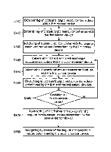
FIG. 4 illustrates a process flow of a method for determining navigation data
according
to an embodiment.
In step S400 positional angle measurement values and track angle measurement
values are determined with a first navigation device 310. The track angle
measurement
values may also be determined with the first navigation device 310 by a gyro
compassing method or a magnetic sensor such as a magnetic compass, or even
manually.
CA 02940085 2016-11-25
Docket: 11253-035 16
In step S420 a second navigation device 320 is initialized with the angular
measurement values determined by the first navigation device 310.
In this process, the first navigation device 310 has an integrity that is
larger than a
predetermined positional angle integrity, i.e. erroneous measurements of the
positional
angle measurement values determined by the first navigation device 310 occur
with a
probability that is smaller than a predetermined positional angle error rate.
The
predetermined positional angle error rate may be 10-9 per hour in this
process. The
second navigation device 320 has a lower integrity than the first navigation
device 310.
The second navigation device 320 generates erroneous measurements of the
positional
angle measurement values with a probability that is larger than the
predetermined
positional angle error rate.
Erroneous measurements of the positional angle measurement values occur, if
one of
the positional angle measurement values deviates by more than a predetermined
positional angle tolerance value from a positional angle reference value. The
positional
angle reference value may be the actual value of the positional angle or a
value of the
positional angle estimated and interpolated from previous measurement values.
The positional angle tolerance value may be adapted according to the situation
and be
e.g. between 4 and 5 .
In step S430 the second navigation device 320 determines continuously track
and
positional angle measurement values after it has been initialized. To this
end, it uses
the measurement values of a satellite navigation system in order to increase
the
accuracy.
In step S440 track and positional angle measurements are continuously
determined
with the first navigation device 310.
In step S450 the positional angles determined by the first and the second
navigation
devices 310, 320 are compared after the required accuracy of the second
navigation
device 320 (i.e. the Kalman filter 326 is fully operating) has been obtained.
In step S460 it is checked whether the deviation of the determined positional
angle
measurement values from each other is below the positional angle tolerance
value. If
this is not the case (N), steps S430 to S460 are repeated.
CA 02940085 2016-11-25
Docket: 11253-035 17
If the values of the deviations of the determined positional angle measurement
values
from each other are below the predetermined positional angle tolerance values
(J), the
first navigation device 310 is re-initialized with the track and positional
angle
measurement values determined by the second navigation device 320.
In step S480 track and positional angle determination and navigation is
carried out by
the re-initialized first navigation device 310 and measurement values for
critical
functions of the aircraft are provided. The second navigation device provides
further
track and positional angle measurement values for uncritical aircraft
functions.
By means of the method described above navigation data can be determined that
satisfy strict requirements on the integrity and the positional angle, track
angle and
position accuracy.