Note: Descriptions are shown in the official language in which they were submitted.
CA 02940146 2016-08-18
WO 2015/124892
PCT/GB2014/050511
METHOD FOR PREDICTING A FAULT IN A CABIN TEMPERATURE
CONTROL SYSTEM OF AN AIRCRAFT
BACKGROUND OF THE INVENTION
Contemporary aircraft have air-conditioning systems that take hot air from the
engines
of the aircraft for use within the aircraft including for use in a cabin of
the aircraft. A
cabin temperature control system may be utilized for controlling temperatures
within
the cabin. Currently, airlines and maintenance personnel wait until a fault or
problem
occurs with the cabin temperature control system and then attempt to identify
the
cause and fix it during either scheduled or, more likely, unscheduled
maintenance.
Fault occurrences are also recorded manually based on pilot discretion.
BRIEF DESCRIPTION OF EMBODIMENTS OF THE INVENTION
In one embodiment, the invention relates to a method of predicting a fault in
a cabin
temperature control system of an air-conditioning system of an aircraft
including
transmitting data related to a temperature, pressure, valve position, or
actuator
position of the cabin temperature control system, comparing the transmitted
data to a
reference value, predicting a fault in the cabin temperature control system
based on
the comparing, and providing an indication of the predicted fault.
BRIEF DESCRIPTION OF THE DRAWINGS
In the drawings:
Figure 1 is a perspective view of an aircraft and a ground system in which
embodiments of the invention may be implemented;
Figure 2 is a schematic view of a portion of an exemplary air-conditioning
system;
Figure 3 is a schematic view of a portion of an exemplary air-conditioning
system;
and
Figure 4 is a flowchart showing a method of predicting a fault in a cabin
temperature
control system according to an embodiment of the invention.
1
CA 02940146 2016-08-18
WO 2015/124892
PCT/GB2014/050511
DESCRIPTION OF EMBODIMENTS OF THE INVENTION
Figure 1 illustrates an aircraft 8 that may include an air-conditioning system
10, only a
portion of which has been illustrated for clarity purposes, and may execute
embodiments of the invention. As illustrated, the aircraft 8 may include
multiple
engines 12 coupled to a fuselage 14, a cockpit 16 positioned in the fuselage
14, and
wing assemblies 18 extending outward from the fuselage 14. While a commercial
aircraft has been illustrated, it is contemplated that embodiments of the
invention may
be used in any type of aircraft, for example, without limitation, fixed-wing,
rotating-
wing, rocket, personal aircraft, and military aircraft. Further, while two
engines 12
have been illustrated on each wing assembly 18, it will be understood that any
number
of engines 12 including a single engine 12 may be included.
The air-conditioning system 10 may form a portion of the environmental control
system of the aircraft 8 and may include a variety of subsystems. For example,
among others, a bleed air system 20, one or more air-conditioning packs 22,
and an air
distribution or cabin temperature control system 24 (Figure 3) may be included
in the
air-conditioning system 10. The bleed air system 20 may be connected to each
of the
engines 12 and air may be supplied to the air-conditioning system 10 by being
bled
from a compressor stage of each engine 12, upstream of the combustor. Various
bleed ports may be connected to various portions of the engine 12 to provide
highly
compressed air to the bleed air system 20. The temperature and pressure of
this bleed
air varies widely depending upon which compressor stage and the RPM of the
engine
12. The air-conditioning packs 22 and cabin temperature control system 24 will
be
described in more detail with respect to Figures 2 and 3 below.
A plurality of additional aircraft systems 30 that enable proper operation of
the
aircraft 8 may also be included in the aircraft 8. A number of sensors 32
related to the
air-conditioning system 10, its subsystems, and the additional aircraft
systems 30 may
also be included in the aircraft 8. It will be understood that any number of
sensors
may be included and that any suitable type of sensors may be included. The
sensors
32 may transmit various output signals and information.
2
CA 02940146 2016-08-18
WO 2015/124892
PCT/GB2014/050511
A controller 34 and a communication system having a wireless communication
link
35 may also be included in the aircraft 8. The controller 34 may be operably
coupled
to the air-conditioning system 10, the plurality of aircraft systems 30, as
well as the
sensors 32. The controller 34 may also be connected with other controllers of
the
aircraft 8. The controller 34 may include memory 36, the memory 36 may include
random access memory (RAM), read-only memory (ROM), flash memory, or one or
more different types of portable electronic memory, such as discs, DVDs, CD-
ROMs,
etc., or any suitable combination of these types of memory. The controller 34
may
include one or more processors 38, which may be running any suitable programs.
The
controller 34 may be a portion of an FMS or may be operably coupled to the
FMS.
A computer searchable database of information may be stored in the memory 36
and
accessible by the processor 38. The processor 38 may run a set of executable
instructions to display the database or access the database. Alternatively,
the
controller 34 may be operably coupled to a database of information. For
example,
such a database may be stored on an alternative computer or controller. It
will be
understood that the database may be any suitable database, including a single
database
having multiple sets of data, multiple discrete databases linked together, or
even a
simple table of data. It is contemplated that the database may incorporate a
number of
databases or that the database may actually be a number of separate databases.
The
database may store data that may include historical air-conditioning system
data for
the aircraft 8 and be related to a fleet of aircraft. The database may also
include
reference values including predetermined threshold values, historic values, or
aggregated values and data related to determining such values.
Alternatively, it is contemplated that the database may be separate from the
controller
34 but may be in communication with the controller 34 such that it may be
accessed
by the controller 34. For example, it is contemplated that the database may be
contained on a portable memory device and in such a case, the aircraft 8 may
include
a port for receiving the portable memory device and such a port would be in
electronic
communication with controller 34 such that controller 34 may be able to read
the
contents of the portable memory device. It is also contemplated that the
database may
be updated through the wireless communication link 35 and that in this manner,
real
3
CA 02940146 2016-08-18
WO 2015/124892
PCT/GB2014/050511
time information may be included in the database and may be accessed by the
controller 34.
Further, it is contemplated that such a database may be located off the
aircraft 8 at a
location such as an airline operation center, flight operations department
control, or
another location. The controller 34 may be operably coupled to a wireless
network
over which the database information may be provided to the controller 34.
While a commercial aircraft has been illustrated, it is contemplated that
portions of
the embodiments of the invention may be implemented anywhere including in a
computer or controller 60 at a ground system 62. Furthermore, the database(s)
as
described above may also be located in a destination server or a controller
60, which
may be located at and include the designated ground system 62. Alternatively,
the
database may be located at an alternative ground location. The ground system
62 may
communicate with other devices including the controller 34 and databases
located
remote from the controller 60 via a wireless communication link 64. The ground
system 62 may be any type of communicating ground system 62 such as an airline
control or flight operations department.
Figure 2 illustrates an exemplary schematic view of a cold air unit also known
as an
air-conditioning pack 22 having a main heat exchanger 70, a primary heat
exchanger
72, compressor 73, a flow control valve 74, a turbine 75, an anti-ice valve
76, a ram
air inlet flap actuator 77, and a controller 78, which may be located within
the cockpit
16 of the aircraft 8 and may be operably coupled to the controller 34.
Further, a
number of sensors 32 have been illustrated as being included within the air-
conditioning pack 22. The sensors 32 may output a variety of data including
data
related to temperatures of the air-conditioning pack 22, pressures of the air-
conditioning pack 22, or valve positions. For example, some of the sensors 32
may
output various parameters including binary flags for indicating valve settings
and/or
positions including for example the state of the valve (e.g. fully open, open,
in
transition, close, fully closed).
4
CA 02940146 2016-08-18
WO 2015/124892
PCT/GB2014/050511
It will be understood that any suitable components may be included in the air-
conditioning pack 22 such that it may act as a cooling device. The quantity of
bleed
air flowing to the air-conditioning pack 22 is regulated by the flow control
valve 74.
The bleed air enters the primary heat exchanger 72 where it is cooled by
either ram
air, expansion, or a combination of both. The cold air then enters the
compressor 73,
where it is re-pressurized, which reheats the air. A pass through the main
heat
exchanger 70 cools the air while maintaining the high pressure. The air then
passes
through the turbine 75, which expands the air to further reduce heat.
Figure 3 illustrates an exemplary diagram of a cabin temperature control
system 24
having a mixer unit 80, recirculation fans 82, a manifold 84, and nozzles 86
that
distribute air into zones 88 within the cabin 89 of the aircraft 8, as well as
a control
mechanism 90. As illustrated, exhaust air from the air-conditioning packs 22
may be
mixed in a mixer unit 80 with filtered air from the recirculation fans 82 and
fed into a
manifold 84. Air from the manifold 84 may be directed through ducts to
overhead
distribution nozzles 86 in the various zones 88 of the aircraft 8. Cabin
temperature
regulating valves also known as trim air valves (not shown) may be utilized to
control
the flow of air through the distribution nozzles 86. A control mechanism 90
may
control the temperature in each zone 88 as well as a variety of other aspects
of the
cabin temperature control system 24. It will be understood that the control
mechanism may be operably coupled to the controller 34. A number of sensors 32
may be included and may output signals related to various aspects of the cabin
temperature control system 24 including temperatures within the zones 88,
pressures
within the cabin temperature control system 24, temperatures of physical
portions of
the cabin temperature control system 24 including duct temperatures, etc.
It will be understood that the controller 34 and the controller 60 merely
represent two
exemplary embodiments that may be configured to implement embodiments or
portions of embodiments of the invention. During operation, either the
controller 34
and/or the controller 60 may predict a fault with the cabin temperature
control system
24. By way of non-limiting example, one or more sensors 32 may transmit data
relevant to various characteristics of the air-conditioning system 10. The
controller 34
and/or the controller 60 may utilize inputs from the control mechanisms,
sensors 32,
CA 02940146 2016-08-18
WO 2015/124892
PCT/GB2014/050511
aircraft systems 30, the database(s), and/or information from airline control
or flight
operations department to predict the fault with the cabin temperature control
system
24. Among other things, the controller 34 and/or the controller 60 may analyze
the
data over time to determine drifts, trends, steps, or spikes in the operation
of the air-
conditioning system 10. The controller 34 and/or the controller 60 may also
analyze
the sensor data and predict faults in the air-conditioning system 10 based
thereon.
Once a fault with the cabin temperature control system 24 has been predicted
an
indication may be provided on the aircraft 8 and/or at the ground system 62.
It is
contemplated that the predicting of the fault with the air-conditioning system
10 or a
subsystem thereof may be done during flight, may be done post flight, or may
be done
after any number of flights. The wireless communication link 35 and the
wireless
communication link 64 may both be utilized to transmit data such that the
fault may
be predicted by either the controller 34 and/or the controller 60.
One of the controller 34 and the controller 60 may include all or a portion of
a
computer program having an executable instruction set for predicting cabin
temperature control system fault in the aircraft 8. Such predicted faults may
include
improper operation of components as well as failure of components of the cabin
temperature control system 24. As used herein the term prediction refers to a
forward-looking determination that makes the fault known in advance of when
the
fault occurs and contrasts with detecting or diagnosing, which refers to a
determination after the fault has occurred. Along with predicting the
controller 34
and/or the controller 60 may detect the fault. Regardless of whether the
controller 34
and/or the controller 60 runs the program for predicting the fault, the
program may
include a computer program product that may include machine-readable media for
carrying or having machine-executable instructions or data structures stored
thereon.
It will be understood that details of environments that may implement
embodiments
of the invention are set forth in order to provide a thorough understanding of
the
technology described herein. It will be evident to one skilled in the art,
however, that
the exemplary embodiments may be practiced without these specific details. The
exemplary embodiments are described with reference to the drawings. These
drawings illustrate certain details of specific embodiments that implement a
module or
6
CA 02940146 2016-08-18
WO 2015/124892
PCT/GB2014/050511
method, or computer program product described herein. However, the drawings
should not be construed as imposing any limitations that may be present in the
drawings. The method and computer program product may be provided on any
machine-readable media for accomplishing their operations. The embodiments may
be implemented using an existing computer processor, or by a special purpose
computer processor incorporated for this or another purpose, or by a hardwired
system. Further, multiple computers or processors may be utilized including
that the
controller 34 and/or the controller 60 may be formed from multiple
controllers. It will
be understood that the controller predicting the fault may be any suitable
controller
including that the controller may include multiple controllers that
communicate with
each other.
As noted above, embodiments described herein may include a computer program
product comprising machine-readable media for carrying or having machine-
executable instructions or data structures stored thereon. Such machine-
readable
media may be any available media, which may be accessed by a general purpose
or
special purpose computer or other machine with a processor. By way of example,
such machine-readable media can comprise RAM, ROM, EPROM, EEPROM, CD-
ROM or other optical disk storage, magnetic disk storage or other magnetic
storage
devices, or any other medium that can be used to carry or store desired
program codes
in the form of machine-executable instructions or data structures and that can
be
accessed by a general purpose or special purpose computer or other machine
with a
processor. When information is transferred or provided over a network or
another
communication connection (either hardwired, wireless, or a combination of
hardwired
or wireless) to a machine, the machine properly views the connection as a
machine-
readable medium. Thus, any such connection is properly termed a machine-
readable
medium. Combinations of the above are also included within the scope of
machine-
readable media. Machine-executable instructions comprise, for example,
instructions
and data, which cause a general-purpose computer, special purpose computer, or
special purpose processing machines to perform a certain function or group of
functions.
7
CA 02940146 2016-08-18
WO 2015/124892
PCT/GB2014/050511
Embodiments will be described in the general context of method steps that may
be
implemented in one embodiment by a program product including machine-
executable
instructions, such as program codes for example, in the form of program
modules
executed by machines in networked environments. Generally, program modules
include routines, programs, objects, components, data structures, etc. that
have the
technical effect of performing particular tasks or implement particular
abstract data
types. Machine-executable instructions, associated data structures, and
program
modules represent examples of program codes for executing steps of the method
disclosed herein. The particular sequence of such executable instructions
or
associated data structures represent examples of corresponding acts for
implementing
the functions described in such steps.
Embodiments may be practiced in a networked environment using logical
connections
to one or more remote computers having processors. Logical connections may
include a local area network (LAN) and a wide area network (WAN) that are
presented here by way of example and not limitation. Such networking
environments
are commonplace in office-wide or enterprise-wide computer networks, intranets
and
the internet and may use a wide variety of different communication protocols.
Those
skilled in the art will appreciate that such network computing environments
will
typically encompass many types of computer system configurations, including
personal computers, hand-held devices, multiprocessor systems, microprocessor-
based or programmable consumer electronics, network PCs, minicomputers,
mainframe computers, and the like.
Embodiments may also be practiced in distributed computing environments where
tasks are performed by local and remote processing devices that are linked
(either by
hardwired links, wireless links, or by a combination of hardwired or wireless
links)
through a communication network. In a distributed computing environment,
program
modules may be located in both local and remote memory storage devices.
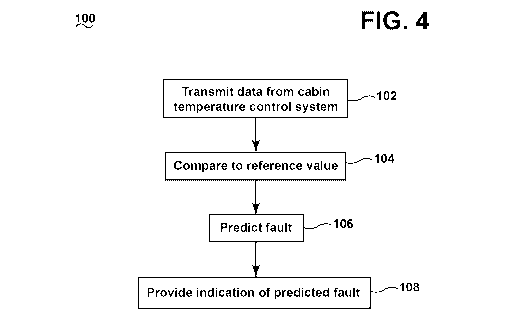
In accordance with an embodiment of the invention, Figure 4 illustrates a
method 100,
which may be used for predicting a fault in the cabin temperature control
system 24 of
the air-conditioning system 10; such a predicted fault may include a predicted
failure.
8
CA 02940146 2016-08-18
WO 2015/124892
PCT/GB2014/050511
The method 100 begins at 102 by transmitting from one or more sensors 32 data
related to the cabin temperature control system 24. More specifically, data
may be
transmitted from one or more sensors 32 outputting data related to
temperatures,
pressures or flow rates, valve positions, actuator positions, etc. for
components of the
cabin temperature control system 24. This may include sequentially and/or
simultaneously transmitting data from one or more of the sensors 32. The
transmitted
data may be received by any suitable device including a database or the
controller 34
and/or the controller 60.
The transmitting of data at 102 may define sensor output(s) relevant to one or
more
characteristics of the cabin temperature control system 24. It is contemplated
that the
senor output(s) may include raw data from which a variety of other information
may
be derived or otherwise extracted to define the sensor output. It will be
understood
that regardless of whether the sensor output is received directly or derived
from
received output, the output may still be considered sensor output. For
example, the
sensor output may be aggregated over time to define aggregated sensor data.
Aggregating the transmitted sensor output over time may include aggregating
the
transmitted sensor output over multiple phases of flight and/or over multiple
flights.
Such aggregated sensor data may include a median value, a maximum value, a
minimum value, etc. Such aggregated sensor data may be reset after a
maintenance
event.
At 104, the transmitted data or sensor output may be compared to a reference
value
for the transmitted data. The reference value may be any suitable reference
value
related to the transmitted data including that the reference value may be a
temperature
value, a pressure value, an acceptable valve, actuator position range, etc.
The
reference value for the transmitted data may also include a predetermined
threshold,
historical values, a value that has been determined during operation, etc.
Alternatively, the reference values may be stored in one of the database(s) as
described above.
In this manner, the sensor output may be compared to a predetermined threshold
for
the sensor output. Any suitable comparison may be made. For example, the
9
CA 02940146 2016-08-18
WO 2015/124892
PCT/GB2014/050511
comparison may include determining a difference between the sensor output and
the
predetermined threshold. By way of non-limiting example, the comparison may
include comparing a recent signal output to a historic value. Comparisons may
be
made on a per flight basis or the data may be processed over a series of
flights.
Comparisons may further measure a change in correlation between two parameters
including where the correlation exceeds a given threshold. In the case where
median
values are calculated for the transmitted data, the comparing at 104 may
include
comparing the median value to the predetermined threshold. Further still when
minimums and maximums for the transmitted data may be determined, the
comparing
at 104 may include comparing the minimums and/or maximums to the predetermined
thresholds.
At 106, a fault in the cabin temperature control system 24 may be predicted
based on
the comparison at 104. More specifically, a fault of a valve, sensor, or
controller in
the cabin temperature control system 24 may be predicted based on the
comparison at
104. For example, a fault in the cabin temperature control system 24 of the
air-
conditioning system 10 may be predicted when the comparison indicates that the
sensor data satisfies a predetermined threshold. The term "satisfies" the
threshold is
used herein to mean that the variation comparison satisfies the predetermined
threshold, such as being equal to, less than, or greater than the threshold
value. It will
be understood that such a determination may easily be altered to be satisfied
by a
positive/negative comparison or a true/false comparison. For example, a less
than
threshold value can easily be satisfied by applying a greater than test when
the data is
numerically inverted.
Any number of faults in the cabin temperature control system 24 of the air-
conditioning system 10 may be determined. By way of non-limiting example,
transmitting the data at 102 may include transmitting a cabin temperature
regulating
valve position. In such an instance, a fault may be predicted with the cabin
temperature regulating valve when the comparison indicates more air passes
through
the cabin temperature regulating valve over time or the comparison indicates
that its
position is increasing over time. Currently, such a fault may only be detected
through
increased occurrences of passenger/cabin staff reports of, typically, hot
cabin
CA 02940146 2016-08-18
WO 2015/124892
PCT/GB2014/050511
compartment temperatures, despite the set temperature being low. Only after
multiple
occurrences, where resets of the cabin temperature control system 24 have not
worked, does further investigation take place by maintenance personnel. Also,
the
mixing of air throughout the cabin 89 means that a fault with a cabin
temperature
regulating valve can go unnoticed as correctly conditioned air from other
zones 88
dilutes the impact.
Sensor faults may be determined by determining a high number of out of range
readings. It will be understood that any number of faults may be predicted
based on
any number of comparisons. These comparisons may also be used to provide
information relating to the severity of the fault.
In this manner, the transmitted data may undergo analysis in relation to
themselves
and to other parameters/features and this information may be used to determine
impending faults and/or degradation and provide associated information such as
severity and prognostic information by highlighting an impending failure of a
particular component. It will be understood that any suitable controller or
computer
may perform one or more portions of the method 100. For example, the
controller 34
and/or the controller 60 may compare the transmitted data, predict the fault,
and
provide the indication. The controller may utilize an algorithm to predict the
fault. In
implementation, the predetermined thresholds and comparisons may be converted
to
an algorithm to predict faults in the cabin temperature control system 24 of
the air-
conditioning system 10. Such an algorithm may be converted to a computer
program
comprising a set of executable instructions, which may be executed by the
controller
34 and/or the controller 60. Alternatively, the computer program may include a
model, which may be used to predict faults in the cabin temperature control
system
24. The model may be implemented in software as an algorithm, such as one or
more
mathematical algorithms.
At 108, the controller 34 and/or the controller 60 may provide an indication
of the
fault in the cabin temperature control system 24 predicted at 106. The
indication may
be provided in any suitable manner at any suitable location including in the
cockpit 16
and at the ground system 62. For example, the indication may be provided on a
11
CA 02940146 2016-08-18
WO 2015/124892
PCT/GB2014/050511
primary flight display (PFD) in a cockpit 16 of the aircraft 8. If the
controller 34 ran
the program, then the indication may be provided on the aircraft 8 and/or may
be
uploaded to the ground system 62. Alternatively, if the controller 60 ran the
program,
then the indication may be uploaded or otherwise relayed to the aircraft 8.
Alternatively, the indication may be relayed such that it may be provided at
another
location such as an airline control or flight operations department.
It will be understood that the method of predicting a fault in the cabin
temperature
control system 24 is flexible and the method illustrated is merely for
illustrative
purposes. For example, the sequence of steps depicted is for illustrative
purposes
only, and is not meant to limit the method 100 in any way, as it is understood
that the
steps may proceed in a different logical order or additional or intervening
steps may
be included without detracting from embodiments of the invention. For example,
it is
contemplated that predicting the fault at 106 may be based on multiple
comparisons at
104. For example, one type of sensor data may be transmitted multiple times
and the
comparisons may compare the data to a predetermined threshold such as a
control
limit. In this
manner, the multiple comparisons may be made over time.
Alternatively, the multiple comparisons may be made with multiple types of
sensor
data or from sensor data from across the aircraft. By way of non-limiting
example,
transmitting the data at 102 may include transmitting a cabin temperature
regulating
valve position and a temperature from at least one temperature sensor 32
operably
coupled to the air-conditioning system 10. The reference value that the
transmitted
temperature may be compared to may include a set temperature. The comparing at
104 may include determining a difference between the transmitted temperature
and
the set temperature and comparing that difference to a temperature reference
difference value. A fault with the cabin temperature regulating valve may be
predicted when the comparisons indicate the valve position is increasing and
the
difference satisfies the temperature reference value. More
specifically, the
comparisons may indicate increased duct temperatures and increased cabin
compartment temperatures for a particular zone 88 and such comparisons may be
used
to predict a fault with a particular cabin temperature regulating valve.
Furthermore, it
is contemplated that the temperature reference value may be determined by the
12
CA 02940146 2016-08-18
WO 2015/124892
PCT/GB2014/050511
controller 34 and/or the controller 60. More specifically, deltas between set
and
actual temperatures as well as deltas between adjacent zones may also be
determined.
Comparisons with such values may allow the abnormal behavior to be more
clearly
identified from the normal variation present in the operation of the system.
For
example, a cabin temperature identified as abnormally hot might be
rationalized/nullified if the corresponding set temperature is high or if the
adjacent
zones are similarly hot, due to, for example, extreme ambient temperatures. By
way of
a further non-limiting example, a pack outlet temperature, outside air
temperature, and
cabin set temperature may be transmitted at 102. In such an instance, a fault
with the
cabin temperature regulating valve may be predicted at 106 when the
comparisons at
104 indicate the valve position is increasing and the transmitted temperatures
are
within normal bounds. In this manner, the fault may be isolated to the cabin
temperature regulating valve.
By way of a further example, it is also contemplated that the transmitted data
may
include data from a plurality of flights, including the pre-flight and/or
cruise portions
of such plurality of flights. In such an instance, comparing the transmitted
data may
include comparing the data from the plurality of flights with related
predetermined
threshold(s). In this manner, multiple comparisons may be made utilizing the
data for
the plurality of flights. Further, predicting the fault may include predicting
the fault
when the comparisons indicate the predetermined thresholds are satisfied a
predetermined number of times and/or over a predetermined number of flights.
Beneficial effects of the above-described embodiments include that data
gathered by
the aircraft may be utilized to predict a fault in the cabin temperature
control system.
This allows such predicted faults to be corrected before they occur. For
example, a
leak in a duct can be indicated by a change in the temperature sensor data for
the duct
relative to past performance under the same or similar environmental
conditions.
Currently there is no manner to predict faults in the cabin temperature
control system
and unanticipated issues occurring during aircraft usage or even known issues,
which
require unplanned maintenance actions, lead to potential operational impacts
for an
airline. The above-described embodiments enable reduction of operational
impacts,
including a reduction in delays for passengers and in the level of unscheduled
13
CA 02940146 2016-08-18
WO 2015/124892
PCT/GB2014/050511
maintenance required as a result of air-conditioning system faults. The above-
described embodiments also help with planning of scheduled maintenance due to
prognostic information supplied. The above-described embodiments allow for
automatic predicting and alerting to users of faults. The above-embodiments
allow
accurate predictions to be made regarding faults in the cabin temperature
control
system and by predicting such problems, sufficient time may be allowed to make
repairs before such faults occur. This allows for cost savings by reducing
maintenance cost, rescheduling cost, and minimizing operational impacts
including
minimizing the time aircraft are grounded.
This written description uses examples to disclose the invention, including
the best
mode, and also to enable any person skilled in the art to practice the
invention,
including making and using any devices or systems and performing any
incorporated
methods. The patentable scope of the invention is defined by the claims, and
may
include other examples that occur to those skilled in the art. Such other
examples are
intended to be within the scope of the claims if they have structural elements
that do
not differ from the literal language of the claims, or if they include
equivalent
structural elements with insubstantial differences from the literal languages
of the
claims.
14