Note: Descriptions are shown in the official language in which they were submitted.
1
TITLE:
Scanning Meta-Material Antenna and Method of Scanning with a
Meta-Material Antenna
BACKGROUND:
Field:
[0002] Various antennas and systems of antennas can benefit from
meta-material construction. For example, avionics antennas including weather
antennas may benefit from being constructed of meta-materials.
Description of the Related Art:
[0003] Conventional weather antennas on aircraft typically include moving
mechanical components. For example, conventional avionics weather radars
use a mechanical gimbal mounted flat plate antenna.
[0004] These conventional weather radars are heavy due to the mechanical
mounting system. Moreover, conventional weather antennas are limited in
antenna gain, due to the use of individual slotted antenna elements having a
positive index ofrefraction.
[0005] E-Scan airborne radars conventionally include expensive flat plate
antenna arrays of active components, each active component driving an
individual antenna element. Due to the large number of active dements, these
radar systems may be less reliable than passive slotted antenna element
designs.
Date Recue/Date Received 2021-08-02
CA 02940292 2016-08-19
WO 2015/127060
PCT/US2015/016594
2
[0006] Additionally, such conventional radars are limited in antenna gain and
have a limited amount of variation of lateral and vertical scan angle, due to
limitations of the antenna element beam forming capability at large off-center
angles. These limitations are, in turn, due to the limited positive index of
refraction.
SUMMARY:
[0007] According to certain embodiments of the present invention, a method
can include electronically scanning, by an antenna of an aircraft, an
environment of the aircraft. The
electronically scanning can include
transmitting or receiving an electrical frequency over the antenna, wherein
the
antenna comprises a negative index of refraction meta-material. The
electronically scanning can also include applying an electric field to control
a
dielectric constant of the antenna.
[0008] In certain embodiments of the present invention, an apparatus can
include avionics circuitry configured to scan an environment of an aircraft in
which the avionics circuitry is installed. The apparatus can also include an
antenna comprising a negative index of refraction meta-material. The avionics
circuitry can be configured to apply an electric field to control a dielectric
constant of the antenna. The avionics circuitry can be configured to scan the
environment of the aircraft using the antenna.
[0009] A method, according to certain embodiments of the present invention,
can include electronically communicating, by an antenna of an aircraft, with a
remote device. The electronically communicating can include transmitting or
receiving an electrical frequency over the antenna, wherein the antenna
comprises a negative index of refraction meta-material. The electronically
communicating can also include applying an electric field to control a
dielectric
constant of the antenna. The electrical frequency can include an avionics
frequency.
CA 02940292 2016-08-19
WO 2015/127060
PCT/US2015/016594
3
BRIEF DESCRIPTION OF THE DRAWINGS:
[0010] For proper understanding of the invention, reference should be made to
the accompanying drawings, wherein:
[0011] Figure 1 illustrates a system according to certain embodiments of the
present invention.
[0012] Figure 2 illustrates another system according to certain embodiments of
the present invention.
[0013] Figure 3 illustrates a method according to certain embodiments of the
present invention.
[0014] Figure 4 illustrates another method according to certain embodiments of
the present invention.
DETAILED DESCRIPTION:
[0015] Certain embodiments of the present invention provide scanning
antennas that include meta-material (MM) flat conformal antenna structures
with a negative index of refraction. These flat conformal antenna structures
with a negative index of refraction can bend an electromagnetic (E-M) radio
frequency (RF) wave several times greater than the bending possible with
positive index of refraction antennas.
[0016] The antenna structure according to certain embodiments of the present
invention does not require arrays of active components in order to generate
and
steer the required RF beam width for the detection of weather. The MM RF
beam can be steered using an electric field applied to a substrate. The
applied
electric field can change the dielectric constant of the MM antenna. Thus, the
index of refraction can be modified to cause the antenna beam to point in a
desired direction. Thus, a relatively low-cost E-Scan avionics weather radar
with an antenna of the same size in existing airplanes today can be created.
Moreover, this antenna can have a smaller beam spot size than conventional
CA 02940292 2016-08-19
WO 2015/127060
PCT/US2015/016594
4
weather radars and consequently can provide higher weather resolution at
greater distances than conventional weather radars.
[0017] Further, the MM E-Scan weather radar of certain embodiments of the
present invention can laterally and vertically scan for weather at greater
angles
than conventional weather radars. Thus, such embodiments can provide the
flight crew with a better field of view of the weather.
[0018] The MM E-Scan antenna can have other advantages, such as being able
to instantaneously point in a desired direction, such as directly forward, to
provide a continuous scan for turbulence and windshear while still providing a
normal full field of view of the weather, even when the aircraft is turning.
This
instantaneous pointing feature can also provide a way to communicate with the
ground or other aircraft with a time slotted type of communication link, such
as
a time division duplex (TDD), time division simplex (TDS), frequency division
and/or multiplexed access, phase, amplitude modulation (AM), or other forms
of communication modulated radio frequency (RF) communication link, at or
near the weather radar frequency.
[0019] The MM antenna can also be electrically tuned such that multiple
frequencies of operation within the normal C-Band or X-Band frequency
bandwidth, for example between about 7.0 to 11.2 GHz or 8.0 to 2.0 GHz, can
be used to provide a faster scan of the weather full field of view. Multiple
frequency transmission can be performed by, for example, transmitting several
pulses in one direction at different frequencies and receiving each of these
pulses with several receivers each tuned to a particular frequency associated
with a particular pulse.
[0020] Such an approach to multiple frequency transmission and reception can
provide appropriate statistical weather range, intensity, and phase
measurements at any given point within the scan angle of the antenna more
rapidly. More rapid acquisition of such information can reduce the overall
time
needed for a full field of view scan of the weather, even when the aircraft is
CA 02940292 2016-08-19
WO 2015/127060
PCT/US2015/016594
turning. Also, the update rate for a particular section of weather, such as a
high
intensity storm, turbulence, or windshear, can be updated more rapidly for
better aircrew situational awareness.
[0021] Figure 1 illustrates a system according to certain embodiments of the
present invention. As shown in Figure 1, a system can include a processor 110.
The processor 110 can be configured to perform a variety of functions
including, but not limited to, weather processing, turbulence processing,
windshear processing, data link processing, and antenna pointing processing.
The processor can be connected to one or more transmitter 120. The
transmitter 120 can be frequency agile. For example, the transmitter 120 can
be capable of transmitting on more than one frequency, such as a multiple of
frequencies within a C-Band or X-Band.
[0022] The system can also include one or several receivers 130. The receivers
130 can be tuned to the multiple frequencies of the transmitter 120, so as to
observe reflected signals that may indicate weather, windshear, turbulence, or
the like. The receivers 130 can also be configured for data link communication
and/or other avionics frequencies.
[0023] The system can also include one or more antenna 140. The antenna 140
can be a MM E-scan antenna, having a negative index of refraction. The
negative index of refraction can be characterized by the following equation:
-n(co)2=c(o))* (co), where c is the permittivity and u is the permeability for
a
given frequency co.
[0024] The system can also include hardware for display/alerting and controls
150. This hardware can, for example, be embodied in a cockpit or can support
other hardware that is provided in a cockpit. The hardware can work in
coordination with the processor 110 to provide a display of weather
conditions,
alerts for weather hazards, alerts for windshear or turbulence, and the like.
The
hardware can also work to provide display, alerting, routing, inputs and
outputs, or mode and frequency control for communication.
CA 02940292 2016-08-19
WO 2015/127060
PCT/US2015/016594
6
[0025] The system can further include memory 160, which can include read
only memory (ROM) or random access memory (RAM). The memory 160
can hold configuration information for the system, and can also save the
information to be displayed via display/alerting and controls 150. The memory
160 can be managed by the processor 110 and can, in certain embodiments, be
located on a same chip with the processor 110, although this is not required.
[0026] Figure 2 illustrates another system according to certain embodiments of
the present invention. As shown in Figure 2, the system can include avionics
circuitry 210, which can be configured to scan an environment of an aircraft
in
which the avionics circuitry 210 is installed. Additionally, the system can
include an antenna 220, which includes a negative index of refraction meta-
material. In certain embodiments, antenna 220 can correspond to antenna 140
in Figure 1, and avionics circuitry 210 can correspond to the remaining
elements of Figure 1.
[0027] The avionics circuitry 210 can be configured to apply an electric field
to
control a dielectric constant of the antenna 220. Also, the avionics circuitry
210
can be configured to scan the environment of the aircraft using the antenna
220.
[0028] The antenna 220 can be a weather radar antenna. Other types of
antennas can also be used in certain embodiments. The antenna 220 can be
statically mounted to an exterior of an aircraft. Optionally, the antenna 220
can
be dynamically mounted, such as on a mechanical gimbal arrangement.
[0029] The avionics circuitry 210 can be configured to electrically tune the
antenna to a plurality of frequencies and sequentially or simultaneously
transmit on the frequencies. The system can also include a plurality of
receivers 230, each tuned to a respective one of the plurality of frequencies.
The plurality of frequencies can be within a C-Band or X-Band frequency
bandwidth.
100301 The avionics circuitry 210 can be configured to scan the environment in
CA 02940292 2016-08-19
WO 2015/127060
PCT/US2015/016594
7
various ways, including over both a variable vertical angle and a variable
lateral angle, or over either of those variable angles. For example, a
vertical
angle window and a lateral angle window, or either of those windows, can be
used.
[0031] The avionics circuitry 210 can include a plurality of meta-material
antennas configured to create a summed signal in space. The plurality of meta-
material antennas can also be combined with one or more conventional
antenna.
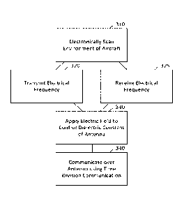
[0032] Figure 3 illustrates a method according to certain embodiments of the
present invention. As shown in Figure 3, a method can include, at 310,
electronically scanning, by an antenna of an aircraft, an environment of the
aircraft.
[0033] The electronically scanning can include, at 320, transmitting an
electrical frequency over the antenna, and/or, at 325, receiving an electrical
frequency over the antenna. The antenna can include a negative index of
refraction meta-material.
[0034] The electronically scanning can include operating a weather radar or
another kind of radar. The scanning can further include electrically tuning
the
antenna to a plurality of frequencies and sequentially or simultaneously
transmitting on the frequencies. The scanning can additionally include
receiving the plurality of frequencies at a plurality of corresponding
receivers.
The plurality of frequencies can be within a C-Band or X-Band frequency
bandwidth. The electronically scanning can include scanning in both a vertical
angle arc and a lateral angle arc. Thus the vertical angle can be variable
and/or
the lateral angle can be variable. Thus, the vertical angle can be varied
through,
for example, a window of angles and likewise the lateral angle can be varied
through, for example, another window of angles.
[0035] The method can also include, at 330, applying an electric field to
control
a dielectric constant of the antenna. The dielectric constant can, in turn, be
CA 02940292 2016-08-19
WO 2015/127060
PCT/US2015/016594
8
used to control the shape of the antenna beam.
[0036] The method can further include, at 340, communicating over the
antenna at the electrical frequency using time division communication. Other
forms of communication are also possible. The time division communication
can include, for example, time division duplex communication or time division
simplex frequency division and/or multiplexed access, phase, AM, or other
forms of communication modulated RF communication.
[0037] Figure 4 illustrates another method according to certain embodiments of
the present invention. As shown in Figure 4, the method can include, at 410,
electronically communicating, by an antenna of an aircraft, with a remote
device. The electronically communicating can include, at 420, transmitting an
electrical frequency over the antenna. The method can also or alternatively
include, at 425, receiving an electrical frequency over the antenna. The
antenna
can include a negative index of refraction meta-material.
[0038] The method can also include, at 430, applying an electric field to
control
a dielectric constant of the antenna. The electrical frequency can be an
avionics
frequency. The method can further include, at 440, communicating data from
the aircraft directly to a target aircraft over the antenna at the electrical
frequency. The communicating can also be done directly to a satellite, boat,
or
ground station. Other targets of the communicating are also possible.
[0039] Other modifications and variations of the above methods and systems
are possible. For example, while time division communication is mentioned,
other forms of communication, such as code division, frequency, amplitude, or
phase modulation, are also possible.
[0040] The methods shown in Figure 3 and Figure 4 may be performed, for
example, by the systems shown in Figures 1 and 2. However, other systems
can also be used for performing these methods.
[0041] One having ordinary skill in the art will readily understand that the
invention as discussed above may be practiced with steps in a different
CA 02940292 2016-08-19
WO 2015/127060
PCT/US2015/016594
9
order, and/or with hardware elements in configurations which are different
than those which are disclosed. Therefore, although the invention has been
described based upon these preferred embodiments, it would be apparent to
those of skill in the art that certain modifications, variations, and
alternative
constructions would be apparent, while remaining within the spirit and scope
of the invention. In order to determine the metes and bounds of the
invention, therefore, reference should be made to the appended claims.