Note: Descriptions are shown in the official language in which they were submitted.
CA 02941144 2016-09-06
AUTOMATED FASTENER INSERT INSTALLATION SYSTEM
FOR COMPOSITE PANELS
BACKGROUND
Field of the Disclosure
The present disclosure is directed to an automated fastener insert
installation
system for composite panels.
Description of Related Art
Composite panels, such as honeycomb-cored sheets, often cannot have
mechanical fasteners directly affixed thereto. In some instances wherein such
a
composite panel may require a mechanical fastener to be affixed thereto, a
fastener-
receiving insert may first be installed in and secured to the composite panel,
and the
mechanical fastener is then engaged with the insert. In this manner, the
mechanical
fastener can be used with the installed insert to secure the composite panel
to other
composite panels or structures.
However, such inserts often require a high degree of precision and
conformance to tolerances when installed in the composite panel in order to
provide
an effective anchor for the mechanical fastener. For example, there may be
several
configurations or sizes of inserts, and each insert requires that the
insertion orifice in
the composite panel be correspondingly configured or sized. It is not
desirable to
install an insert configured for a through-hole orifice in a blind-hole-
configured orifice,
and vice versa. Moreover, insert-receiving-orifice defined by the composite
panel
must have an appropriate diameter and/or length/depth corresponding to the
diameter
and/or length of the insert received thereby. Further, the inserts may have to
be
installed so as to be as close to flush or coplanar with the outer surface of
the
composite panel as possible, in order to provide optimal interaction with the
mechanical fastener and structural integrity of the assembled end product. In
addition,
such an insert may often be installed in the composite panel using an adhesive
material (i.e., a special purpose two-part potting compound). However, such a
special
purpose potting compound typically requires careful handling, but also has a
limited
1
time in which it can be applied once mixed or actuated. Also, such a potting
compound cures and hardens, once applied, which may limit re-work
opportunities in
the event of an imprecise insert installation procedure. In some instances,
one
imprecise insert installation in a composite panel will, at a minimum, require
labor
intensive rework, and may cause that composite panel to be designated as
scrap.
As such, there exists a need for a system and method for installing fastener
inserts in composite panels that addresses issues in a conventional process.
SUMMARY OF THE DISCLOSURE
The disclosure describes an automated fastener insert installation system for
use in a composite panel fastener insert installation process The system
includes an
analysis device configured to determine a configuration or a size of an insert-
receiving
orifice defined by and extending through a major surface of a composite panel,
the
configuration of the insert-receiving orifice including whether the insert-
receiving orifice
was formed in a through-hole configuration or a blind¨hole configuration, and
the size
of the insert-receiving orifice including a lateral size or a longitudinal
size of the insert-
receiving orifice. The system also includes a manipulation device in
communication
with the analysis device and configured to select and retrieve one of a
plurality of
fastener inserts engaged with an installation aide, in response to the
configuration or
the size of the insert-receiving orifice determined by the analysis device,
and to insert
the selected fastener insert into the insert-receiving orifice such that the
installation
aide engages the major surface of the composite panel. The system also
includes an
adhesive dispenser device configured to dispense an adhesive material through
adhesive application orifices defined by the installation aide and the
selected fastener
insert, and into the insert-receiving orifice about selected fastener insert,
such that the
adhesive material interacts with the selected fastener insert and the
composite panel
defining the insert-receiving orifice so as to secure the selected fastener
insert within
the insert-receiving orifice.
The analysis device may include a laser measurement system or a machine
vision analysis system.
2
CA 2941144 2019-11-14
The manipulation device may be configured to select a corresponding one of
the plurality of fastener inserts engaged with the installation aide,
according to the
determined configuration and size of the insert-receiving orifice.
The installation aide may include an adhesive material on a surface thereof
engaging the fastener insert, and the manipulation device may be configured to
insert
the selected corresponding one of the plurality of fastener inserts into the
insert-
receiving orifice such that the surface of the installation aide engages and
adheres to
the major surface of the composite panel having the insert-receiving orifice
extending
therethrough, so as to support the selected corresponding one of the plurality
of
fastener inserts at a desired position within the insert-receiving orifice.
The system may include an adhesive preparation device engaged with the
adhesive dispenser device and configured to mix and actuate the adhesive
material in
an adhesive material kit.
The adhesive material kit may include a multiple-part adhesive compound, the
multiple parts of the adhesive compound, when mixed, forming the actuated
adhesive
material.
The adhesive dispenser device may be configured to receive the adhesive
material kit from the adhesive preparation device, to dispense the actuated
adhesive
material from the adhesive material kit.
The adhesive preparation device or the adhesive dispenser device may be
configured to limit dispensation of the actuated adhesive material from the
adhesive
material kit to within a predetermined working time.
The adhesive preparation device may be configured to prepare a subsequent
adhesive material kit for mixing and actuation of the adhesive material
therein prior to
expiration of the working time of the actuated adhesive material in a previous
adhesive material kit received by the adhesive dispenser device.
The adhesive preparation device or the adhesive dispenser device may be
configured to monitor dispensation of the actuated adhesive material from the
adhesive material kit with respect to a predetermined working time, and to
direct the
adhesive preparation device to prepare a subsequent adhesive material kit for
mixing
3
CA 2941144 2019-11-14
and actuation of the adhesive material therein prior to an earlier occurrence
of
exhaustion of the actuated adhesive material or expiration of the working time
of the actuated adhesive material, within a previous adhesive material kit
received by the adhesive dispenser device.
The adhesive preparation device or the adhesive dispenser device may
be configured to limit dispensation of the actuated adhesive material from the
adhesive material kit to within a predetermined dispensation amount of the
actuated adhesive material.
The adhesive dispenser device may be configured to dispense the
actuated adhesive material from the adhesive material kit through the
installation aide and into the insert-receiving orifice about selected
fastener
insert, and to exert a negative pressure on the actuated adhesive material,
upon dispensation of a selected amount of the actuated adhesive material from
the adhesive material kit, so as to retract excess actuated adhesive material
back into the adhesive material kit.
The adhesive material kit may include a container having the actuated
adhesive material therein, and the adhesive dispenser may be configured to
decrease a volume of the container to dispense the actuated adhesive material
through a nozzle associated with the container, and to increase the volume of
the container to exert the negative pressure on the actuated adhesive material
and retract excess actuated
adhesive material back into the container via
the nozzle.
4
Date Recue/Date Received 2020-06-08
The aspects, functions and advantages discussed herein may be
achieved independently in various example implementations/aspects or may be
combined in yet other example implementations/aspects, further details of
which may be seen with reference to the following description and drawings.
BRIEF DESCRIPTION OF THE DRAWINGS
Having thus described the disclosure in general terms, reference will now
be made to the accompanying drawings, which are not necessarily drawn to
scale, and wherein:
FIG. 1 schematically illustrates a fastener insert installation
system,
according to one aspect of the present disclosure;
FIG. 2 schematically illustrates a panel handling system and a
fastener insert installation system, according to one aspect of
the present disclosure;
FIG. 3 schematically illustrates a fastener insert assembly system,
according to one aspect of the present disclosure;
FIG. 4 schematically illustrates an adhesive
material
preparation system, according to one aspect of the present
disclosure;
FIG. 5A schematically illustrates an example configuration of a
blind hole fastener insert, according to one aspect of the
present disclosure;
FIG. 5B schematically illustrates an example configuration of a
Date Recue/Date Received 2020-06-08
through-hole fastener insert, according to one aspect of the present
disclosure; and
FIG. 6 schematically illustrates an adhesive material kit,
according to one aspect of the present disclosure.
6
Date Recue/Date Received 2020-06-08
CA 02941144 2016-09-06
DETAILED DESCRIPTION OF THE DISCLOSURE
The present disclosure now will be described more fully hereinafter with
reference to the accompanying drawings, in which some, but not all aspects of
the
disclosure are shown. Indeed, the disclosure may be embodied in many different
forms and should not be construed as limited to the aspects set forth herein;
rather,
these aspects are provided so that this disclosure will be thorough and
complete, will
fully convey the scope of the disclosure to those skilled in the art, and will
satisfy
applicable legal requirements. Like numbers refer to like elements throughout.
As
used in this specification and the claims, the singular forms "a," "an," and
"the" include
plural referents unless the context clearly dictates otherwise.
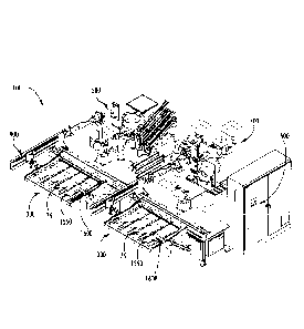
As schematically illustrated in FIG. 1, one aspect of the present disclosure
provides an automated fastener insert installation system 100, which may be
particularly applicable to composite panels, such as, for example, a honeycomb-
cored
sheet. Such a system 100 may generally comprise a panel handling module or
system 300, an adhesive material preparation module or system 500, a fastener
insert
assembly module or system 700, and a fastener insert installation module or
system
900, configured to cooperate to automatically insert a fastener insert 50
(see, e.g.,
FIGS. 5A and 5B) into a composite panel 75.
The panel handling module or system 300 as shown, for example, in FIG. 2, is
configured to receive and secure the composite panel 75 with respect to an
origin
1100 of a first coordinate system 1200. The composite panel 75 is generally in
the
form of a sheet, and has opposed major surfaces 75A, 75B (see, e.g., FIGS. 5A
and
5B). In some instances, the fastener insert installation system 100 may be a
downstream process receiving a previously-processed composite panel 75. That
is, in
a previous upstream process, the composite panel 75 may be processed through a
milling machine/device (not shown) configured to form at least one insert-
receiving
orifice 25 in the composite panel 75, with the at least one orifice 25
extending through
one of the major surfaces 75A, 75B of the composite panel 75.
The panel handling module 300 includes opposing frame members 320, 340,
wherein at least one of the frame members 320, 340 is movable (i.e.,
pivotable) with
7
CA 02941144 2016-09-06
respect to the other frame member. With the frame member(s) 320, 340 moved to
be
in an open position with respect to each other, the panel handling module 300
is
configured to receive the composite panel 75 therebetween. If necessary or
desired,
either or both frame members 320, 340 may have adjustable supports 360 engaged
therewith, wherein the supportg 360 may be moved or re-arranged, as necessary
to
assist in supporting composite panels having different configurations. The
frame
members 320, 340 may then be moved to a closed position with respect to each
other
to thereby secure the composite panel 75 therebetween.
According to aspects of the disclosure, the composite panel 75 may be secured
by the frame members 320, 340, and the adjustable supports 360, if
implemented, of
the panel handling module 300, such that one of the major surfaces 75A, 75B of
the
composite panel 75 is externally accessible. Moreover, the frame members 320,
340,
and the adjustable supports 360, if implemented, are configured and arranged
such
that the at least one insert-receiving orifice 25 defined by the composite
panel 75 is
externally accessible. In some instances, the composite panel 75 may be
configured
to receive fastener insert(s) 50 through both major surfaces 75A, 75B of the
composite
panel 75. That is, both major surfaces 75A, 75B may define at least one insert-
receiving orifice 25. In such instances, the frame members 320, 340 may be
collectively mounted so as to be rotatable over at least 180 degrees, such
that both
major surfaces 75A, 75B of the composite panel 75 are externally accessible.
In this
manner, the frame members 320, 340 may be configured to secure the composite
panel 75 in one orientation such that one of the major surfaces 75A, 75B is
externally
accessible for installation of appropriate fastener inserts 50 therein,
wherein the frame
members 320, 340 can then be collectively rotated 180 degrees such that the
other of
the major surfaces 75A, 75B is externally accessible such that appropriate
fastener
inserts 50 can then be installed therein.
In some aspects, a registration arrangement 1300 may be operably engaged
with one or both of the frame members 320, 340. In general, the registration
arrangement 1300 may be configured to interact with the composite panel 75
such that
the composite panel 75 is registered with respect to the first coordinate
system 1200
upon being secured by the frame members 320, 340 in the closed position. In
one
8
CA 02941144 2016-09-06
example, either or both of the frame members 320, 340 may be configured such
that,
upon receipt of the composite panel 75 therebetween, the composite panel 75
interacts with an alignment provision (i.e., a mechanical guide) of the
registration
arrangement 1300 configured to engage one or more features of the composite
panel
75 upon insertion thereof, which thereby automatically aligns the composite
panel 75
with the first coordinate system 1200 with respect to the origin 1100 thereof.
In other instances, the registration arrangement 1300 may be configured to
examine the composite panel 75 secured by the frame members 320, 340, and
determine therefrom the relationship of the secured composite panel 75 to the
first
coordinate system 1200. For example, the registration arrangement 1300 may
comprise an image acquisition device (i.e., a digital camera) in communication
with a
computer device 1500. Images of the secured composite panel captured by the
image
acquisition device may be directed to the computer device 1500, and features
of the
composite panel determined by image analysis / machine vision processing. The
origin 1100 and the first coordinate system 1200 may thus be registered with
the
analyzed image of the composite panel 75 to align the composite panel with the
first
coordinate system 1200.
Registration of the composite panel 75 with the first coordinate system 1200
may be implemented by the fastener insert installation system 100 with regard
to
installing fastener inserts 50 in corresponding insert-receiving orifices 25
defined by
the composite panel 75. That is, the fastener insert installation system 100
may be
configured to determine the locations of the insert-receiving orifices 25 in
the
composite panel 75, according to the first coordinate system 1200, in order to
implement an automated fastener insert installation process. As such, in some
aspects, the composite panel 75 may have been previously processed upstream
through a milling machine/device (not shown) to form the insert-receiving
orifices 25 in
either or both of the major surfaces 75A, 75B of the composite panel 75. In
forming
the insert-receiving orifices 25, the milling machine (i.e., a CNC-programmed
milling
machine) may implement machine code detailing the parameters associated with
the
orifices 25. For instance, the machine code may include details related to the
locations/coordinates of the orifices 25 in relation to a coordinate system
(i.e., a
9
CA 02941144 2016-09-06
"second coordinate system") associated with the composite panel 75, as well
as, for
example, the configuration of each orifice (La, whether a through-hole
configuration or
a blind hole configuration) and the size (i.e., lateral size or longitudinal
size) of each
orifice.
Since at least some of this same information included in the machine code is
required by the automated fastener insert installation process, aspects of the
present
disclosure provide that the computer device 1500 is configured to receive or
read the
machine code implemented by the previous upstream milling machine (i.e., the
CNC
milling program) for the composite panel 75 subsequently received by the panel
handling module 300 of the fastener insert installation system 100. That is,
in some
aspects, the computer device 1500 or the registration arrangement 1300
associated
therewith may be configured such that the first coordinate system 1200
corresponds
with the second coordinate system used by the upstream milling machine. As
such,
upon the first and second coordinate systems being associated by the computer
device 1500 / registration arrangement, a programming output from the milling
machine program code may be used to create fastener insertion data for driving
the
fastener insert installation process, for example, by allowing the computer
device 1500
to identify the insert-receiving orifices 25 and categorize the orifices 25
according to
configuration, size, and coordinates (location) with respect to the composite
panel 75
or the identified origin 1100 associated therewith. On this basis, the
computer device
1500 may be configured to specify the fastener insert configuration (i.e.,
type) or size
or other specification for installation in each orifice 25, an efficient order
of installation
of the fastener inserts 50 across either or both major surfaces 75A, 75B of
the
composite panel 75, and, if necessary, may move or adjust any of the supports
360
engaged with the frame member(s) 320, 340 so as to assure external access to
the
orifices 25 for fastener insert installation.
In order to ascertain that the composite panel 75 received by the panel
handling
module 300 corresponds to the milling machine program code received by the
computer device 1500, the panel handling module 300 may implement certain
panel
identification measures to minimize or eliminate the risk of an improper
fastener insert
installation process occurring with the composite panel 75. For example,
general
CA 02941144 2016-09-06
identification of the composite panel 75, and information associated with the
configuration of each insert-receiving orifice 25 therein, the size of each
insert-
receiving orifice 25 therein, and/or the coordinates of each insert-receiving
orifice 25 in
the second coordinate system may be incorporated into a coded indicium (i.e.,
a bar
code or other machine readable code) 1550 associated with the composite panel
75.
In such instances, the computer device 1500 or registration arrangement 1300
may
further include a code reader device 1600 configured to read the coded
indicium 1550
associated with the particular composite panel 75 received and secured between
the
frame members 320, 340 and to communicate the general identification
information
and at least information associated with the coordinates of the insert-
receiving orifice
in the second coordinate system to the computer device 1500 / registration
arrangement 1300 for association with the first coordinate system 1200.
Implementation of the image acquisition device and/or the code reader device
1600
may further allow a feedback loop or system to be implemented by the computer
device 1500 to ascertain, for example, that the same software revision and/or
revision
of the product specification for the particular composite panel 75 was / is
being
implemented by the upstream milling machine, as well as the fastener insert
installation system 100. The information processed in the feedback loop may
thus
facilitate and ensure, for instance, that the correct fastener insert 50 is
being installed
in the particular orifice 25, that the correct size of the fastener insert 50
is being
selected for the diameter of the orifice 25 or the depth of the composite
panel 75, or
that any supports 360 associated with the frame member 320, 340 are not
impeding
access to any of the orifices 25 receiving a fastener insert 50.
The fastener insert assembly module or system 700 as shown, for example, in
FIG. 3, is configured to engage each of a plurality of fastener inserts 50
with an
installation aide 45. As shown in FIGS. 5A and 5B, a fastener insert 50 for
composite
panels 75, as disclosed herein, generally includes a body portion 62, an
engagement
end 64 engaged with one end of the body portion 62, and a retention end 66
engaged
with the other end of the body portion 62. FIGS. 5A and 5B schematically
illustrate
two example fastener inserts 50, wherein the fastener insert 50 illustrated in
FIG. 5A
has a "blind hole" configuration, and the fastener insert 50 illustrated in
FIG. 5B has a
11
CA 02941144 2016-09-06
"through hole" configuration. The engagement end 64 of the fastener insert 50
defines
a plurality of adhesive application orifices 65 extending therethrough from an
engagement surface 68 of the engagement end 64, distal to the body portion 62.
When installed in the insert-receiving orifice 25 of the composite panel 75,
the fastener
insert 50 is preferably disposed such that the engagement surface 68 is as
close to
flush with the one of the major surfaces 75A, 75B defining the orifice 50, as
possible
(i.e., within a tolerance of about 0.005 inches). As such, it may be desirable
to support
the fastener insert 50 within the orifice 25 such that the engagement surface
68 is as
close to flush as possible with the major surface of the composite panel 75,
while an
adhesive material is directed through the adhesive application orifices 65 and
into the
insert-receiving orifice 25 about the body portion 62 of the fastener insert
50, wherein
the adhesive material, upon curing, interacts between the fastener insert 50
and the
portion of the composite panel 75 defining the insert-receiving orifice 25 to
retain and
secure the fastener insert 50 therein. In order to support the fastener insert
50 in the
desired position within the orifice 25, an installation aide 45 (i.e., a
temporary planar
tab having a lateral dimension greater than the lateral dimension of the
orifice 25) may
be affixed to the engagement surface 68 of the fastener insert 50. As such,
upon
insertion of the fastener insert 50 in the orifice 25, the installation aide
45 engages the
major surface about the orifice 25 and supports the engagement surface 68
close to
flush with the major surface, while the adhesive material is directed through
the
adhesive application orifices 65 and about the fastener insert 50 within the
orifice 25.
Since the fastener insert 50 must be assembled with the installation aide 45
prior to the fastener insert installation process, a further aspect of the
present
disclosure provides a fastener insert assembly module or system 700 which may
initially be configured to sort the fastener inserts 50 by configuration
(i.e., according to
a through-hole insert configuration or a blind-hole insert configuration) or
size (i.e.,
according to a lateral size or a longitudinal size) thereof. For example, the
fastener
assembly module 700 may include three separate hoppers 710, 720, 730 for
receiving
three different configurations or sizes of fasteners inserts 50. In one
instance, one
hopper 710 may receive a first configuration/size of a through hole insert, a
second
hopper 720 may receive a second configuration/size of a through hole insert,
and a
12
CA 02941144 2016-09-06
third hopper 730 may receive a first configuration/size of a blind-hole
insert. An
alignment provision may be associated with each hopper 710, 720, 730 such that
respective fastener inserts 50 fed therethrough are aligned with respect to
each other
(i.e., such that the longitudinal axes of the fastener inserts 50 are parallel
to each
other).
A fastener insert manipulation device 750 (i.e., a robotic arm) as shown, for
example, in FIG. 3, is configured to select from among the sorted and aligned
fastener
inserts 50, and to manipulate the selected fastener insert 50 so as to engage
the
engagement surface 68 of the fastener insert 50 with an engagement surface 47
of an
installation aide 45. The installation aides 45 may be affixed (i.e., by a
temporary
adhesive) to an elongate sheet material 760 in a serial manner, wherein the
sheet
material 760 can then be wrapped about a roll. The rolled sheet material 760
may be
fed to an interaction location so that the installation aides 45 engaged
therewith are
sequentially presented such that the engagement surface 47 thereof is exposed
for
interaction with one of the fastener inserts 50. The engagement surface 47 may
have
an adhesive material (i.e., a temporary adhesive) engaged therewith. Since
each
fastener insert 50 defines a plurality of adhesive application orifices 65
spaced apart
about the engagement surface 68, and since each installation aide 45 defines a
plurality of adhesive application orifices 40 spaced apart about an engagement
surface
47 thereof, the fastener insert manipulation device 750 may also be configured
to align
the adhesive application orifices 65 of each fastener insert 50 with
corresponding
adhesive application orifices 40 of the installation aide 45.
Such alignment of the adhesive application orifices 65, 40 may be
accomplished, for example, by a machine vision / feedback system (not shown)
in
communication with the fastener insert manipulation device 750. The machine
vision /
feedback system may be configured to guide the fastener insert manipulation
device
750 to orient the fastener insert 50 selected thereby, until the adhesive
application
orifices 65 thereof correspond and align with the adhesive application
orifices 40 of the
installation aide 45 at the interaction location. Once the adhesive
application orifices
65, 40 of the fastener insert 50 and the installation aide 45 are aligned, the
fastener
insert manipulation device 750 causes the engagement between the engagement
13
CA 02941144 2016-09-06
surfaces 68, 47. The fastener insert manipulation device 750 then moves the
fastener
insert 50, now engaged with the installation aide 45, away from the
interaction location
such that the installation aide 45 is removed from adherence to the sheet
material.
The fastener insert manipulation device 750 is subsequently configured to
orient each
fastener insert engaged with one of the installation aides into an insertion
orientation
relative to the installation aide, and to store the fastener insert such that
no external
forces are exerted on the interface between the fastener insert 50 and the
installation
aide 45 that could cause misalignment between the adhesive application
orifices 65,
40. In some instances, a fastener insert supply device 800 may be configured
to
receive the fastener inserts 50, each engaged with respective installation
aides 45,
from the fastener insert manipulation device 750, with the fasteners inserts
50 oriented
in the insertion orientation relative to the installation aide 45 and sorted
according to
the configuration or the size thereof. For example, the fastener insert supply
device
800 may comprise a series of conveyors 820, 840, 860 each configured to store
and
serve as a staging area for the different fastener insert / installation aide
configurations
or sizes, wherein a selected one of the fastener insert / installation aide
assembly is
already oriented for insertion into the insert receiving orifice 25 in the
composite panel
75, and wherein the opportunities for misalignment of the fastener insert /
installation
aide assemblies between each other, as well as misalignment between the
fastener
insert 50 and the installation aide 45, are limited or minimized.
As previously disclosed, typical fastener inserts 50 of the types herein may
often be installed in the composite panel 75 using a special purpose two-part
potting
compound as an adhesive material. However, such a special purpose potting
compound may include, for example, weight-reducing glass microspheres, which
typically require careful handling to avoid damage to the microspheres. As
such, bulk
mixing and dispensing provisions may not necessarily be desirable or
appropriate for
such types of adhesive materials. In addition, once actuated by mixing the two
parts
of the potting compound, the actuated adhesive material has a limited time in
which it
can be applied (i.e., on the order of 12 minutes maximum application life),
and thus the
amount of the actuated adhesive material that can be dispensed in connection
with the
fastener insert installation process is likewise limited. In such instances,
one practical
14
CA 02941144 2016-09-06
solution may be mixing and dispensing small batches of the potting compound,
and
timing the mixing of a series of small batches to optimize the dispensation of
the
actuated adhesive material during the fastener insert installation process.
The adhesive material preparation module or system 500 as shown, for
example, in FIG. 4, may thus be configured to receive one or more adhesive
material
kits 550, for example, of the type shown in FIG. 6, and to mix and actuate the
adhesive
material therein. As illustrated, each adhesive material kit 550 may comprise
a tubular
body 560 having the two components of the adhesive material therein separated
by a
membrane (not shown). A plunger/mixer 570 extends longitudinally outward from
the
tubular body 560. In order to actuate the adhesive material, the plunger/mixer
570 is
urged longitudinally with respect to the tubular body 560 so as to rupture the
membrane and introduce the two parts of the potting compound to each other
within
the tubular body 560. The plunger/mixer 570 may be subsequently rotated about
the
longitudinal axis and simultaneously translated along the longitudinal axis
such that
the two parts of the potting compound are thoroughly mixed and the adhesive
material
actuated (which starts the timing of the application life of the actuated
adhesive
material). Removal of the plunger/mixer 570 from the tubular body 560,
following the
actuation of the adhesive material therein, leaves a dispensation opening (not
shown)
in the tubular body 560 through which actuated adhesive material is dispensed.
The adhesive material preparation module 500 may be configured to include a
supply device 600 for receiving un-actuated adhesive material kits 550 in a
suitable
arrangement for providing a continuous supply for use in the fastener insert
installation
process, with each kit 550 being in a suitable orientation for selection by a
manipulation device 625 (i.e., a robotic arm) controlled by a controller
device (i.e., the
computer device 1500 or other appropriate computer device). Upon selection of
a kit
550 from the supply device 600, the kit is moved to a mixing device 650,
wherein the
kit 550 is then processed to actuate the adhesive material therein. The kit
550 having
the actuated adhesive material is then delivered to the fastener insert
installation
module 900 for use in the fastener insert installation process. In this
regard, as
previously disclosed, the actuated adhesive material in a kit 550 may have an
effective
application lifetime on the order of about 11 or 12 minutes. As such, the
actual
CA 02941144 2016-09-06
working time in which a kit 550 may be used to dispense the actuated adhesive
material may be on the order of about 7 or 8 minutes in order, for instance,
to produce
a suitable margin of effectiveness before the actuated adhesive material
proceeds to
cure. The adhesive material preparation module 500 may thus also be configured
to
prepare a subsequent adhesive material kit 550 for mixing and actuation of the
adhesive material therein prior to expiration of the working time of the
actuated
adhesive material in a previous adhesive material kit 550.
Due to the sensitive timing requirements involved with the use of the adhesive
material kits 550, the adhesive material preparation module 500 may also be
configured to monitor the operational time for each kit 550. In this regard,
the
adhesive material preparation module 500 may also be in communication with the
controller device for control and/or monitoring thereof. In regard to the
timing of the
kits 550, a time stamp may be associated with a kit 550 upon actuation of the
adhesive
material within the kit 550 at the mixing device 650, for example, by scanning
a coded
indicium (i.e., a bar code) associated with the kit 550 and initiating a timer
limited to a
predetermined working time, which may be, but is not necessarily, less than
the
effective application lifetime of the actuated adhesive material in the kit
550. Upon
expiration of the working time, the kit 550 is recalled by the controller,
recovered and
discarded, and replaced with a subsequent kit 550 having actuated adhesive
material
therein and subject to the same time stamp limitations as the previous kit
550.
It may be possible that the dispensation of the actuated adhesive material
from
a kit 550 causes the actuated adhesive material in that kit 550 to be
exhausted prior to
the expiration of the working time. As such, in some instances, each kit 550
may be
monitored by the controller device, either directly or indirectly, to
determine the amount
of the actuated adhesive material dispensed or the amount of the actuated
adhesive
material remaining. Direct monitoring may be accomplished, for example, with
an
appropriate sensor in communication with the computer device 1500.
Indirect
monitoring may be accomplished, for example, through analysis of the order and
the
configurations of the fastener inserts and the installation rate of the
fastener insert
installation process for a particular composite panel 75 to determine usage of
the
actuated adhesive material in a kit 550 in comparison to the working time
limit. In any
16
CA 02941144 2016-09-06
event, the adhesive material preparation module 500 is configured to minimize
process down time upon the expiration of a current kit 550 by way of the
controller
determining that expiration of the current kit 550 and directing the adhesive
material
preparation module 500 (i.e., the manipulation device 625 and the mixing
device 650)
to prepare a subsequent kit 550 for deployment at an appropriate time after
the
expired kit 550 is recovered and discarded.
The fastener insert installation module or device 900 as shown, for example,
in
FIG. 2, may be engaged with or disposed in proximity to the panel handling
module
300, and may include an analysis device 925 configured to determine a
configuration
or a size of the insert-receiving orifice 25 defined by and extending through
a major
surface of the composite panel 75 received and secured by the panel handling
module
300. A manipulation device 950 is in communication with the analysis device
925 and
is configured to select and retrieve one of the plurality of fastener inserts
50 engaged
with the installation aide 45, in response to the configuration or the size of
the insert-
receiving orifice 25 determined by the analysis device 925. The manipulation
device
950 is also configured to deliver the selected fastener insert 50 to a
fastener
installation / adhesive dispenser device 975 configured to insert the selected
fastener
insert 50 into the insert-receiving orifice 25 such that the installation aide
45 engages
the major surface 75A, 75B of the composite panel 75. The fastener
installation /
adhesive dispenser device 975 is further configured to dispense the actuated
adhesive
material from the adhesive material kit 550 and through the adhesive
application
orifices 65, 40 defined by the installation aide 45 and the selected fastener
insert 50,
and into the insert-receiving orifice 25 about selected fastener insert 50,
such that the
actuated adhesive material interacts with the selected fastener insert 50 and
the
composite panel 75 defining the insert-receiving orifice 25 so as to secure
the selected
fastener insert 50 within the insert-receiving orifice 25 upon curing of the
actuated
adhesive material. The manipulation device 950 may also be configured to
retrieve an
adhesive material kit 550 from the adhesive material preparation module 500,
deliver
the kit 550 to the fastener installation / adhesive dispenser device 975, and
recover the
kit 550 from the fastener installation / adhesive dispenser device 975 and
discard the
kit 550 upon expiration thereof.
17
CA 02941144 2016-09-06
Initially, the analysis device 925 is configured to inspect the composite
panel 75
secured by the panel handling module 300 to determine or confirm whether the
insert-
receiving orifice 25 defined by the composite panel 75 was formed in a through-
hole
configuration or a blind-hole configuration, and/or determine or confirm a
location, a
lateral size (i.e., diameter) or a longitudinal size (i.e., the thickness of
the composite
panel 75) of the insert-receiving orifice 25. In
making such determinations or
confirmations, the analysis device 925 may implement, for example, machine
vision,
laser measurements, or the like. In some instances, the analysis device 925
may be
in communication with the computer device 1500. In
such instances, the
configuration, size, and/or coordinates (location) of the insert-receiving
orifice(s) 25
defined by and extending through a major surface of the composite panel 75
received
and secured by the panel handling module 300, may already be known by way of
the
machine code received from the prior upstream milling process. Accordingly,
the
information gathered by the analysis device 925 may serve to verify or confirm
the
information included in the machine code from the upstream milling process.
Once the parameters of the insert-receiving orifice 25 have been determined or
confirmed by the analysis device 925, the manipulation device 950 is directed
to
retrieve one of the fastener inserts 50 of the appropriate configuration and
size (and
having the installation aide 45 engaged therewith) from one of the series of
conveyors
820, 840, 860 (staging area) of the fastener insert supply device 800 of the
fastener
insert assembly module 700, and to deliver the selected fastener insert 50 in
an
appropriate orientation to the fastener installation / adhesive dispenser
device 975 for
installation in the composite panel 75. The installation aide 45 engaged with
the
selected fastener insert 50 may include an adhesive material (i.e., a
temporary
adhesive) on the engagement surface 47 thereof engaging engagement surface 68
of
the fastener insert 50. The fastener installation / adhesive dispenser device
975is
further configured to insert the selected fastener insert 50 into the insert-
receiving
orifice 25, for instance, such that the fastener insert 50 is centered within
the orifice 25.
Upon insertion of the fastener insert 50 into the orifice 25, the portion of
the
engagement surface 47 exceeding the lateral dimension of the engagement end 64
of
the fastener insert 50 engages and adheres, via the adhesive material, to the
major
18
CA 02941144 2016-09-06
surface 75A, 75B of the composite panel 75 defining the insert-receiving
orifice 25. In
this manner, the installation aide 45 secures the fastener insert 50 in a
desired position
within the orifice 25, and supports the engagement surface 68 of the fastener
insert 50
substantially flush with the major surface 75A, 75B or the composite panel 75.
The manipulation device 950 may also be configured to retrieve an adhesive
material kit 550 containing the actuated adhesive material (i.e., potting
compound)
from the adhesive material preparation module 700, and to deliver the kit 550
to the
fastener installation / adhesive dispenser device 975. The fastener
installation /
adhesive dispenser device 975 is further configured to align the dispensation
opening
of the tubular body 560 of the kit 550 with each adhesive application orifice
40, 65
extending through the installation aide 45 and the engagement end 64 of the
fastener
insert 50, in turn. For each adhesive application orifice 40, 65, the actuated
adhesive
material is dispensed from the kit 550 by the fastener installation / adhesive
dispenser
device 975 by reducing the volume of the tubular body 560 of the adhesive
material kit
550. For example, the tubular body 560 may include a movable end plate (not
shown)
engaged therewith opposite to the dispensation opening, wherein the fastener
installation / adhesive dispenser device 975 may be configured to move the end
plate
toward the dispensation opening along the tubular body 560 in order to reduce
the
volume within the tubular body 560 and dispense the actuated adhesive material
through the dispensation opening. The dispensed actuated adhesive material
enters
the insert-receiving orifice 25 about the body portion 62 of the fastener
insert 50 and is
sufficiently viscous so as to flow to fill the space between the fastener
insert 50 and
the portion of the composite panel 75 defining the orifice 25 (i.e., the
honeycomb
material structure). In some instances, the actuated adhesive material is
dispensed
until a certain excess amount or overfill flows back outwardly of the
particular adhesive
application orifice 40, 65, at which time the fastener installation / adhesive
dispenser
device 975 ceases dispensing the actuated adhesive material from the kit 550.
In
some instances, the appropriate excess amount realized through the adhesive
application orifice 40, 65 before ceasing the dispensation of the actuated
adhesive
material may be determined, for example, by the analysis device 925 using
machine
vision. For example, it may be specified that a sufficient amount of the
actuated
19
CA 02941144 2016-09-06
adhesive material has been dispensed into the orifice 25 about the fastener
insert 50
when an adhesive overflow of about 0.25 inches long is detected and determined
by
the analysis device 925.
Due to the viscous nature of the actuated adhesive material, the dispensation
opening of the adhesive material kit 550 may remain in contact with the
dispensed
actuated adhesive material when the fastener installation / adhesive dispenser
device
975 is directed to cease dispensation. In some instance, the fastener
installation /
adhesive dispensation device 975 may be further configured to exert a negative
pressure on the actuated adhesive material, upon dispensation of a selected
amount
of the actuated adhesive material from the adhesive material kit 550, in
order, for
example, to retract excess actuated adhesive material from the dispensation
opening
back into the tubular body 560 of the adhesive material kit 550. That is, for
instance,
the fastener installation / adhesive dispenser device 975, upon being directed
to cease
dispensation of the actuated adhesive material from the kit 550, may retract
the end
plate of the kit 550 away from the dispensation opening by a predetermined
amount so
as to expand the effective volume of the tubular body 560 and exert a negative
pressure on the actuated adhesive material about the dispensation opening. In
such
instances, the application of the negative pressure may break the flow of the
actuated
adhesive material from the dispensation opening and provide a cleaner tail end
of the
dispensed actuated adhesive material and/or the excess amount / overflow
associated
therewith. The break of the actuated adhesive material may be further
facilitated, in
some instances, by the fastener installation / adhesive dispenser device 975
moving
the dispensation opening of the kit 550 away from the adhesive application
orifice 40,
65 concurrently with the application of the negative pressure of the kit 550.
Some
results of this procedure may be, for instance, a cleaner dispensation opening
of the
kit 550 for subsequent dispensing of the actuated adhesive material therefrom
and/or
preventing contamination of the composite panel 75 from excess adhesive
material.
Once the dispensation process for one of the adhesive application orifices 40,
65 is completed, the fastener installation / adhesive dispenser device 975 is
configured
to move the dispensation opening of the kit 550 to each of the adhesive
application
orifices 40, 65, in turn, until all such adhesive application orifices 40, 65
are
CA 02941144 2016-09-06
determined to demonstrate the specified overflow amount of the actuated
adhesive
material. As previously disclosed, in some instances, the fastener insert
installation
module 900 or a component thereof may be configured to limit dispensation of
the
actuated adhesive material from the adhesive material kit 550 to within a
predetermined working time, or to otherwise monitor the dispensation of the
actuated
adhesive material from a kit, and to direct the current kit 550 to be replaced
with a
subsequent kit 550 upon expiration of the current kit 550. Once the fastener
insert
installation process is completed and the adhesive material is cured, the
installation
aides 45 can be removed from the composite panel 75 by dissolving or otherwise
negating the adhesive material securing the installation aide 45 to the major
surface
75A, 75B, along with removing any excess/overflow amounts of the cured
adhesive
material extending outwardly of the adhesive application orifices 40, 65.
Many modifications and other aspects of the disclosures set forth herein will
come to mind to one skilled in the art to which these disclosures pertain
having the
benefit of the teachings presented in the foregoing descriptions and the
associated
drawings. Therefore, it is to be understood that the disclosures are not to be
limited to
the specific aspects disclosed and that equivalents, modifications, and other
aspects
are intended to be included within the scope of the appended claims. Although
specific terms are employed herein, they are used in a generic and descriptive
sense
only and not for purposes of limitation.
21