Note: Descriptions are shown in the official language in which they were submitted.
DUAL SIDED RAZOR
CROSS-REFERENCE TO RELATED APPLICATIONS
[0001] This application claims the benefit of U.S. Provisional Patent
Application,
No. 61/948,203, filed March 5, 2014.
FIELD OF THE INVENTION
[0002] The present invention relates generally to shaving systems, and
more
particularly to a replaceable, double-sided blade unit for a shaving system.
BACKGROUND
[0003] Typical razors have one-five blades only on one side, and when
they get
dull, they are thrown away. A typical consumer either buys disposable razors
or
replacement cartridge type razors. The disposable razors are less expensive,
and the
replacement cartridge type razors cost significantly more. One problem is that
consumers
are forced to pay high prices for razors with cartridges and even higher
prices for the
replacement cartridges that are sold.
SUMMARY
[0004] Since many consumers do not want to pay high prices for razors but
have
no choice in the matter, the dual sided razor allows consumers to have a
longer shave by
having a razor cartridge that the consumer can use both sides of the
cartridge. This can
save consumers money, so they don't have to buy as many razor replacement
cartridges
during the year because the razor can last twice as long. The dual sided razor
provides
consumers a market in the middle. This invention gives consumers another
choice in
shaving by offering consumers a double shave, preserving quality, and saving
consumers
money.
- 1 -
Date Recue/Date Received 2021-08-09
CA 02941647 2016-09-02
WO 2015/134700
PCT/US2015/018872
[0005] With the dual sided razor, there are from one to five blades in a
dual sided
cartridge, and there is a sharp edge for shaving on each end of the blade.
This way, the
consumer can use one side of the razor until it is dull, and then use the
other side of the
razor cartridge, thereby shaving twice as long. The razor utilizes both ends
of the razor
blade instead of wasting the other end of the razor blade that is not used for
shaving or is
not designed for shaving. The user then disconnects the double-sided razor
cartridge from
the handle engagement connection, flips over or turns over the razor
cartridge, and
attaches it to the other side of the dual sided cartridge razor. The user
would use this
second side of the razor cartridge until it's dull. When the razor cartridge
is dull, the user
would take the dual sided cartridge off and apply a new dual sided cartridge
to the razor
handle. This should give consumers double the shave utilizing both ends of the
razor
blade.
[0006] A user could buy a razor that comes with the dual sided cartridges
already
attached. Or, the user could buy replacement cartridges and replace the
existing dual
sided razor cartridges.
[0007] To connect and disconnect the razor to and from the dual sided
cartridge,
the user would hold the handle with one hand, and hold the dual sided
cartridge ends (the
end and sides where there are no blades) with the other hand. Then, the user
would put
the handle engagement connection areas, located on the handle, into the
attachment
compartment on the cartridge face connection compartments or slots until it
connects, fits
inside, and preferably locks into the cartridge compartment area.
[0008] In one embodiment, an easy connection occurs if the razor handle and
the
handle engagement connection are perpendicular to the cartridge attachment
compartment face when inserting (connecting or disconnecting). There can be
many
ways of inserting (connecting or disconnecting) the handle engagement
connection (razor
handle) and the dual sided cartridge, known now or developed in then future.
While
certain embodiments are described herein, it will be appreciated that other
embodiments
are contemplated.
- 2 -
CA 02941647 2016-09-02
WO 2015/134700
PCT/1JS2015/018872
3
[0009] The present disclosure allows consumers to save money by providing
twice the shave as normal razors and cartridges. This way, consumers can spend
less
money a year on razors. This concept is very useful and is much needed in the
marketplace. Unlike previous concepts of a two-sided razor, the razor of the
present
embodiments described herein has a new and improved way to bring consumers a
dual
sided razor with a great shave, double the shave, thereby saving consumers
money.
There are many unique aspects of the present disclosure that make it an easy
way for
consumers to use a razor cartridge that can be used to shave on both sides.
[0010] The dual sided razor designed as a dual sided disposable razor can
have all
the specifications replaceable and elements mentioned in this application. The
dual sided
disposable razor can be any shape, design, size and be made of any material
known now
or developed in the future. One non-limiting difference between a dual sided
disposable
razor and a dual sided non-disposable razor is that the disposable razor
blades and
cartridges might be made of less expensive materials and designed to be used
only a
limited number of times and thrown away.
BRIEF DESCRIPTION OF THE DRAWINGS
[0011] FIG. 1 is a perspective view of one embodiment of a razor system
comprising one embodiment of a cartridge of the present disclosure connected
to an
embodiment of a handle of the present disclosure;
[0012] FIG. 2 is an exploded view and FIG. 3 is a partially assembled view
of one
embodiment of a cartridge;
[0013] FIGS. 4-5 are perspective rear views of an embodiment of a handle
engaged with a cartridge, with FIG. 4 showing an engagement/release position
and FIG.
showing a use position with the cartridge pivoted away from the
engagement/release
position;
[0014] FIG. 6 is a perspective front view of one embodiment of a handle
without
a cartridge;
CA 02941647 2016-09-02
WO 2015/134700
PCT/US2015/018872
4
[0015] FIG. 7 is a perspective front view of one embodiment of a cartridge
embodiment connected to the handle of FIG. 6;
[0016] FIG. 8 is a perspective rear view of one embodiment of a handle
embodiment containing a logo;
[0017] FIG. 9 is a perspective rear view of one embodiment of a cartridge
connected to the handle of FIG. 8;
[0018] FIG. 10 is a perspective front view of one embodiment of a handle
containing one embodiment of a handle engagement;
[0019] FIG. 11 is a perspective rear view of the handle of FIG. 10;
[0020] FIG. 12 is a diagrammatic view of one embodiment of a swivel
connection;
[0021] FIG. 13 is a diagrammatic view of one embodiment of a "T"
connection;
[0022] FIG. 14 is a diagrammatic view of one embodiment of a half "T" or
"L"
connection;
[0023] FIG. 15 is a diagrammatic view of one embodiment of a half "T" or
"L"
connection;
[0024] FIG. 16 is a diagrammatic view of one embodiment of an elongated or
long bar connection;
[0025] FIG. 17 is a diagrammatic view of one embodiment of an elongated or
long bar connection;
[0026] FIG. 18 is a front view of one embodiment of a handle of the present
disclosure;
[0027] FIG. 19 is a partially exploded view of the handle of FIG. 18
showing one
embodiment of a spring pin connection;
[0028] FIG. 20 is a perspective view of one embodiment of a cartridge of
the
present disclosure;
[0029] FIG. 21 is a perspective view of one embodiment of a cartridge of
FIG. 20
connected to an embodiment of a handle of the present disclosure;
CA 02941647 2016-09-02
WO 2015/134700
PCT/US2015/018872
[0030] FIG. 22 is a cross-sectional taken along line 22-22 in FIG. 21;
[0031] FIG. 23 is a perspective top view of one embodiment of a cartridge;
[0032] FIG. 24 is a front view of one embodiment of a cartridge;
[0033] FIG. 25 is cross-sectional view taken along line 25-25 of FIG. 24;
[0034] FIG. 26 is a rear view of one embodiment of a cartridge with a
cover;
[0035] FIG. 27 is a perspective top view of one embodiment of a covered
cartridge;
[0036] FIG. 28 is a rear view of one embodiment of a cartridge connected to
a
handle;
[0037] FIG. 29 is a perspective top view of one embodiment of cartridge
with a
cover attached to the opposite face;
[0038] FIG. 30 is a side view of the cartridge of FIG. 29;
[0039] FIG. 31 is an exploded view of one embodiment of a cartridge of the
present disclosure;
[0040] FIG. 32 is a top edge view of one embodiment of a cartridge of the
present
disclosure;
[0041] FIG. 33 is a left side elevation view thereof;
[0042] FIG. 34 is a front plan view thereof;
[0043] FIG. 35 is a right side elevation view thereof;
[0044] FIG. 36 is a bottom edge view thereof;
[0045] FIG. 37 is a top perspective view thereof;
[0046] FIG. 38 is a close-up of the circled portion 38 of FIG. 34;
[0047] FIG. 39 is a cross-section taken along line 39-39 of FIG. 34;
[0048] FIG. 40 is a top view of one embodiment of a handle in accordance
with
the present disclosure;
[0049] FIG. 41 is a side view thereof;
100501 FIG. 42 is a bottom exploded view thereof; and
CA 02941647 2016-09-02
WO 2015/134700
PCT/US2015/018872
6
[0051] FIG. 43 is a diagrammatic view of one embodiment of a kit including
a
handle and a plurality of cartridges.
DETAILED DESCRIPTION OF THE PREFERRED EMBODIMENTS
[0052] The description of illustrative embodiments according to principles
of the
present invention is intended to be read in connection with the accompanying
drawings,
which are to be considered part of the entire written description. In the
description of
embodiments of the invention disclosed herein, any reference to direction or
orientation
is merely intended for convenience of description and is not intended in any
way to limit
the scope of the present invention. Relative terms such as "lower," "upper,"
"horizontal,"
"vertical," "above," "below," "up," "down," "top" and "bottom" as well as
derivative
thereof (e.g., "horizontally," "downwardly," "upwardly," etc.) should be
construed to
refer to the orientation as then described or as shown in the drawing under
discussion.
These relative terms are for convenience of description only and do not
require that the
apparatus be constructed or operated in a particular orientation unless
explicitly indicated
as such. Terms such as "attached," "affixed," "connected," "coupled,"
"interconnected,"
and similar refer to a relationship wherein structures are secured or attached
to one
another either directly or indirectly through intervening structures, as well
as both
movable or rigid attachments or relationships, unless expressly described
otherwise.
Moreover, the features and benefits of the invention are illustrated by
reference to the
exemplified embodiments. Accordingly, the invention expressly should not be
limited to
such exemplary embodiments illustrating some possible non-limiting combination
of
features that may exist alone or in other combinations of features; the scope
of the
invention being defined by the claims appended hereto.
[0053] This disclosure describes the best mode or modes of practicing the
invention as presently contemplated. This description is not intended to be
understood in
a limiting sense, but provides an example of the invention presented solely
for illustrative
purposes by reference to the accompanying drawings to advise one of ordinary
skill in the
CA 02941647 2016-09-02
WO 2015/134700
PCT/US2015/018872
7
art of the advantages and construction of the invention. In the various views
of the
drawings, like reference characters designate like or similar parts.
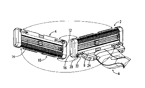
[0054] As seen in Figure 1, one embodiment of a razor cartridge 2 of the
present
disclosure has an upper end section 4, which is furthest away from the handle
6 as
illustrated. The upper end section can be shaped like an oval, rounded, or
have any shape.
If it is rounded, then the cartridge face 8 can have rounded pads, strips, or
moisturizing
pads, or other attachments or features as desired. The lower section (end
sections) 10, or
any sections of the razor, can be shaped any way known now or developed in the
future.
The cartridge ends or edges 12 can have rubber, or any material known now or
developed
in the future, to help the user grip the cartridge ends 12, such as while in
water or out of
water. The edges may be contoured, ridged, concave, convex or combinations of
the
same. This also helps the user grasp and connect or disconnect the cartridge 2
from the
handle 6, and switch (flip) the cartridge 2 along an axis running along the
central
longitudinal axis of the cartridge to use the other size of the razor as
illustrated in Figure
1. When handling the dual sided razor, it is preferred that the user holds the
cartridge
ends or edges 12 and not the blade 14 itself or cartridge face 8. The user
could get cut
holding the blade 14 or cartridge face 8. The cartridge ends 12 can have
finger grooves
16, where there is a concave and/or convex area for the user's fingers to fit
comfortably
and grip the cartridge 2 easily and securely. The cartridge face 8 also
preferably contains
a cartridge attachment compartment 20 into which handle engagement connections
22 fit.
The handle engagement connection 22 extends off of a flange 24 (arms or wing
area).
There can be rounded pads, strips, or moisturizing pads that match the shape
of the
cartridge top, bottom, or sides.
[0055] The cartridge 2 can be made of any type of material, such as
plastic,
rubber, metal, or the like, combinations of the same. Any type of material,
such as
rubber, can be located anywhere on the cartridge 2. The cartridge 2 can be
made of any
number of pieces. The cartridge 2 can be assembled with screws, snap fit, heat
welded,
ultrasonically welded, locked, or any way known now or developed in the
future. The
CA 02941647 2016-09-02
WO 2015/134700
PCT/US2015/018872
8
cartridge 2 can be any size or shape. In one embodiment, it can be designed
and shaped
like straight edge razors or cartridge type razors. The cartridge 2 can have
any amount of
blades 14, fastened permanently or non-permanently, such as one-blade, two-
blades,
three-blades, five-blades. The blades 14 can be any angle degree percentage to
the
shaving surface, however it is preferred to have the blades oriented at sixty
degrees to the
shaving surface, although other angles are possible.
[0056] In one embodiment, the cartridge halves or pieces can be snapped
together
permanently or be removable. It can be attached any way known now or developed
in the
future. It is preferred if the cartridge pieces form a permanent attachment.
Once the two
cartridge halves are attached together, then the cartridge 2 can be heat
sealed or
ultrasonically welded together to make a permanent attachment so it cannot
come apart
which makes it safer. The ultrasonic welding or heat sealing ensures the snap
fit or any
type of connection will keep the cartridge pieces and razors intact as one, so
it never
comes apart, making it very safe. The cartridge pieces can be held together
with metal or
a steel band that holds the two ends together. Other means of securing are
possible. The
bands can hold the two cartridge pieces together securely. There are many ways
that the
cartridge pieces can be bonded or attached securely that is known now or
developed in
the future.
[0057] The cartridge face 8, or the shaving surface side, can be designed
as two
different pieces or be designed as one piece. In one embodiment of a one-piece
design,
the topside, such as where pads and moisturizing pads are located, can look
the same.
The other side (inside surface or interior area), in one embodiment, can be
designed to
look the same where the blades 14 are attached.
[0058] As seen in the embodiment of Figures 2 and 3, there is provided
blade
grooves 18 into which the blades 14 are inserted, in a right angle, for a
right blade angle
on the shaving surface. The angle will be suitable for one side of the
cartridge 2 for the
shaving surface (side one). The other end of the blade groove 18, which the
blades 14 fit
into, is suitable for the other shaving surface (side two) of the cartridge 2.
As seen in
CA 02941647 2016-09-02
WO 2015/134700
PCT/US2015/018872
9
Figures 4 and 5, there is a blade centerpiece 26 that goes through the middle
of each
razor blade 14 to stabilize and hold the razor in place on the inside of the
cartridge 2.
Figure 4 illustrates the attachment of the handle to a face of the blade
cartridge, where the
blade cartridge is suitably angled to receive and engage the handle, whereas
Figure 5
illustrates the pivoting of the cartridge relative to the handle into a use
position for
shaving. When it is desired to remove the cartridge from the handle, the
cartridge is
pivoted from the position shown in Figure 5 to the position shown in Figure 4
and then
the cartridge is capable of being separated from the handle.
[0059] There can be connections where the blade centerpiece 26 is attached
securely and permanently to the cartridge surface, once the blade centerpiece
26 goes
through the blades 14. The connection can be heat or ultrasonically welded or
any way to
attach and connect that is known now or developed in the future. This blade
centerpiece
26 helps the razor blade 14 be sturdy, especially in the middle section of the
razor blade
14. The middle section of the blade 14 needs stabilization because of the
blade span, so
the blade centerpiece 26 helps keep the blades 14 straight and strong while
shaving. This
blade centerpiece 26 can be made of any material or plastic. The razor blade
14 is
designed and shaped to be able to fit this blade centerpiece 26 securely.
[0060] The blade centerpiece 26 is placed down the center of the razor
blade 14
as shown in Figure 2 or it can go through any part of the razor blade 14 other
than the
center. Once the blade centerpiece 26 goes through the center of the blades
14, then the
blade centerpiece 26 can be attached permanently or non-permanently to the one
side of
the cartridge 2. Then the other side of the cartridge can be placed over the
blades 14,
blade centerpiece 26, and the other interior part of the cartridge 2. They can
be
sandwiched together by a snap fit or any connection known now or developed in
the
future. The blades 14 that go into the blade grooves 18 will have one of the
top or free
ends exposed, and as the top cartridge 2 fits over the blades 14 and blade
centerpiece 26,
the top side of the blades 14 will fit into the blade grooves 18 on the
interior part of the
other cartridge 2 side.
CA 02941647 2016-09-02
WO 2015/134700
PCT/US2015/018872
[0061] The other cartridge 2 side (interior side) can be designed to have
the
interior portion fit perfectly together and form one unit where there is a
connection.
There can be snap fit mechanisms or any type of connection known now or
developed in
the future. One side can have connection prongs (male section) and the other
side can
have the prong compartment areas (female sections) where the prong goes inside
and
cannot come back out. So each interior razor cartridge can have one side that
has prongs
and the other side has the connection compartments.
[0062] In one embodiment, each cartridge piece or half can be identical,
and when
the two cartridge pieces or halves are connected together, the user would have
to turn the
cartridge 2 around so opposite ends are attached and connected to each other.
The dual
sided razor can be designed without having to turn the cartridge around. When
attaching
the cartridges, both cartridge attachment compartment areas and pushpin
engagement
areas (the attachment face) are opposite from one another. The interior
portion is
preferably configured to look the same with blade grooves 18 and placement for
the
blades. One difference is with the prongs and the prong compartment connection
areas;
one is on each long end of the cartridge interior.
[0063] In one embodiment, the cartridge can also be two different designed
pieces, or be any number of pieces, to accomplish the same. The cartridge can
be
designed differently on the inside and outside but still remain connected
together. The
cartridge can remain connected together any way known now or developed in the
future.
[0064] As seen in the embodiment of Figures 6 and 7, the handle 6 has an
attachment at each end where the handle 6 can attach to each side of the
cartridge face 8
or any location. This is what makes the handle 6 of this dual sided razor
unique, namely
that it attaches to and engages with a cartridge face. There is a flange 24
(arms or wing
area) at the end of the handle 6 and two handle engagement connection areas 22
that fit
inside both ends of the cartridge attachment compartments 20 (swivel
compartments).
100651 The flange 24 (arms or wing area) can be any shape, size, or design.
The
two handle engagement connections 22 on the handle 6 can be any shape or size
and can
CA 02941647 2016-09-02
WO 2015/134700
PCT/US2015/018872
11
have one to any number handle engagement connections 22 to connect to the
cartridge 2.
The handle engagement connections 22 can be any shape, size, or design, such
as round
or oval, known now or developed in the future. The handle 6 and handle
engagement
connection 22 areas can be any size or shape and can be made from material
known now
or developed in the future.
[0066] The handle 6 and/or flange 24 (arms or wing area) can have a grip
insert
made of a rubber or plastic grip type material that is injected into the
plastic. Or,
materials, plastic, or rubber gripping can be attached on the front or back of
the handle 6
or anywhere on the cartridge 2 or cartridge ends 12. The handle 6 can be made
from, for
example, plastic, rubber, plastic rubber, steel, stainless steel, or any kind
of material
known now or developed in the future. The handle 6 can be chrome plated or
have
chrome. Other materials are contemplated.
[0067] The flange 24 (arms or wing area) that extends from the handle 6 can
be
angled to provide the proper angle and position during the shave and in
relation to the
handle 6. As a user holds the handle 6 and shaves, the shave is easy,
comfortable, and all
contours and surfaces of shaving are covered. The flange 24 (arms or wing
area) could
be any angle. There could be one to any number of flanges (arm or wing area)
24. The
handle engagement connection ends that connect the cartridge can be any shape,
oblong,
oval, round, arrow, shaped, square, any combination, or any design or shape
known now
or developed in the future. Other shapes are contemplated.
[0068] As seen in Figures 8 and 9, the handle 6 can also contain logos or
branding
marks 28. The logos or branding marks 28 can be made of rubber inserts, for
example.
The rubber inserts can be made of any material that aids the user in gripping
the surfaces
while being wet or under water, such as rubber or plastic. Other materials,
types of
branding, logo placements and the like are contemplated.
[0069] As seen in the embodiment of Figures 10 and 11, the handle
engagement
connections 22 are in the form of a round (cylindrical) connection 30, and
this round
(cylindrical) connection 30 area attaches to the cartridge face 8 or inside
the cartridge
CA 02941647 2016-09-02
WO 2015/134700
PCT/US2015/018872
12
attachment compartment 20. The cartridge face 8 has a unique attachment area
to mate
with the handle engagement connection 22. The cartridge face 8 connection area
typically
would mate the shape of the handle engagement connection 22 or fit like a
puzzle (one
piece fits into the outer shape of another piece). The handle engagement
connection 22
can be stiff and or flexible and made of any material known now or developed
in the
future.
[0070] The connection area between the cartridge 2 and handle 6 can be
flush with
the shaving surface, recessed, or the same height as blades 14 or pads. The
connection
surface can have areas inside it to aid the handle 6 to be able to swivel. The
cartridge 2
can be attached to the handle attachment connections by putting one handle
engagement
connection 22 in first, and then connecting another handle engagement
connection 22
inside the cartridge connection area (see Figure 4). Or, the handle engagement
connection 22, or connections, can be inserted at the same time. Removing the
cartridge 2
from the handle engagement connections 22 can be done one at a time or at the
same
time. It is preferred that the cartridge is initially angled relative to the
handle as shown in
Figure 4 during the engagement and disengagement of the cartridge with the
handle.
100711 The swivel angle (attachment area degree) can be any amount. While
shaving, the handle 6 is guided by the user. As the user glides among the
different angles
of any skin location, such as the face, under arms, or legs, the cartridge 2
swivels at
different degrees around the handle engagement connection 22. The inside of
the
cartridge attachment compartment 20 area and the outside surface of the handle
engagement connection 22 move back and forth and swivel while in use.
[0072] Certain cartridges have the wing swivel area attached to the
cartridge and
the handle attaches to this wing swivel area. If the dual sided razor
cartridge of the
present disclosure had a built-in flanges (arms or wing area) 24, the area
could be any
size, angle, shape, or design known now or developed in the future. The handle
engagement connection 22 area can be any shape or size or design, and it can
have a
connection known now or developed in the future that will accomplish the same
purpose.
CA 02941647 2016-09-02
WO 2015/134700
PCT/US2015/018872
13
[0073] The handle engagement connections 22, which can be rounded, are
preferably only rounded to a certain percentage. This percentage of the
rounded portion
can determine the degree that the cartridge 2 will swivel. The percentage can
also
determine the degree that the handle engagement connection 22, or connections,
area will
swivel inside the cartridge attachment compartment area 20. This is one way
the
swiveling can work, although it can work anyway known now or developed in the
future.
This handle attachment type not only connects to both sides of the cartridge
face 8, but it
also has a special connection or connections that allow a portion of the
handle
engagement connection to have the cartridge compartment connection area swivel
around
it, to one or any number of degrees or angles. The percentage can also allow a
portion of
the cartridge compartment connection area to swivel around the handle
engagement
connection to one or any number of degrees or angles. The engagement
connection
between the handle and the cartridge is also designed and configured to
prevent improper
placement of the cartridge relative to the handle, and is also designed and
configured to
prevent over-rotation of the handle relative to the cartridge. This is a very
unique aspect
of the handle of the present disclosure.
[0074] As seen in the embodiment of Figure 12, the handle engagement
connection 22 area can also be designed to attach to swivel connections that
are already
attached to the dual sided cartridge 2. The handle engagement connection 22
can also
attach inside a swivel compartment area 32 of the dual sided cartridge 2.
There would be
cartridges 2 and swivel compartment areas 32 on both sides. There would be a
swivel bar
piece 32a that goes inside each swivel compartment area 32 of the dual sided
cartridge
face 8 and attaches (connects together) separately or as one piece. This
section would
swivel within the cartridge area. Then, the handle engagement connection 22
would
attach to the swivel bar piece 32a. Figure 12 illustrates one embodiment of
attaching the
handle to the dual sided razor cartridge. All other specifications described
can be used
enclosed in this type of attachment.
CA 02941647 2016-09-02
WO 2015/134700
PCT/US2015/018872
14
[0075] As seen in
the embodiment of Figure 13, the attachment compartment area
on the cartridge face can have a "T" shape connection 34: a long, narrow
horizontal
opening 34a with a smaller perpendicular opening 34b running downward below
the long
horizontal opening 34a. There are two connection areas, one on the handle 6
and one the
cartridge face. The "T" shape handle engagement connections, fit through the
cartridge
perpendicular opening 34b and move up and down at the same time the user
shaves.
There can be one to several "T" connections 34 and several handle engagement
connections on the handle 6. There can also be one to several cartridge
attachment
compartments on both ends of the cartridge face. The "T" connection areas 34
can be
any size or shape designed now or known in the future to accomplish the same
concept,
including a shape other than a
100761 The
horizontal opening 34a is an attachment compartment. The horizontal
opening 34a is also a connection and disconnection area for the handle
engagement
connections to connect to and disconnect from. The perpendicular opening 34b,
which
runs downward the middle of the horizontal opening 34a, runs in the direction
away from
the blades 14. The perpendicular opening 34b is usually smaller in length than
the
horizontal opening 34a, but the perpendicular opening 34b can be any size or
length. This
perpendicular opening 34b is a portion of the flange 24 (arms or wing area)
where the
handle engagement connection is attached. The flange 24 (arms or wing area)
runs back
and forth within the perpendicular opening 34b as the user shaves. When the
user shaves
and the cartridge face follows the shaving surface, the cartridge can swivel
back and
forth. While the cartridge swivels back and forth, the flange 24 (arms or wing
area) runs
back and forth within the perpendicular opening 34b.
[0077] As seen in
the embodiment of Figures 14 and 15, there can be a half ("1/2")
"T" or an "L" connection 36, where the upper horizontal section 36a of the
connection
area resembles the 'A "T" or "L" that the lower leg portion 36b is connected
to. The upper
horizontal portion 36a of the "T" would only be shaped as the V2 "T" or "L,"
so that there
would only be one section of the horizontal section 36a of the "T." This upper
horizontal
CA 02941647 2016-09-02
WO 2015/134700
PCT/US2015/018872
section 36a runs toward the outside of the cartridge area, and the inner part
of the "T" is
eliminated. The cartridge and handle connection area are shaped to match the
I/2 "T" or
"L" connection 36. The inside of the 1/2 "T" or "L" connection may have a snap
connection or any connection possible. The inside of the connection area can
also have a
bump area as described herein to hold the handle engagement connection in
place. There
can be one to any number of bumps (Figure 22) located anywhere in and around
the
compartment area. If the handle engagement connection 22 has a half "T"
connection 36,
then the cartridge attachment compartment 20 will also look like a half a "T,
so that the
handle engagement connections 22 fit inside perfectly.
[0078] As seen in
the embodiment of Figure 16, another type of 1/2 "T" connection
38 is when an upper horizontal portion 38a of the "T" would only be shaped as
the
"T," so the there would only be one section of the horizontal portion 38a
section of the
"T". This upper horizontal portion runs toward the middle pushpin engagement
56 area
on the cartridge face. This is an opposite 1/2 "T" connection 38 from the 1/2
"T" 36
embodiment described above, represented by Figures 14 and 15. The outside of
the
cartridge attachment compartment area and the outer handle engagement
connections are
eliminated in this embodiment. The cartridge attachment compartment area and
opening
on the cartridge would be shaped to match the 1/2 "T" connection 38 on the
handle 6, for a
perfection connection.
[0079] As seen in
the embodiment of Figure 17, another type of connection on the
end of the handle engagement connection area can be one long bar 40 that fits
into the
cartridge attachment compartment area, running along the cartridge face 8,
that is also
shaped as one long bar 40. The middle of that cartridge attachment compartment
20 area
can have a recessed area where the long bar engagement area 40a goes. A
pushpin 42 on
the handle 6 can also be built into the middle of the long bar 40 area to
engage with the
cartridge long bar engagement area 40a. The long bar 40 connection can have
one long
bar, running along the front of the handle 6, connected to two flanges (arms
or wing area)
24. The middle section can be wide enough so the flanges (arms or wing area)
24, which
CA 02941647 2016-09-02
WO 2015/134700
PCT/US2015/018872
16
hold the long bar handle engagement connection 22, would have enough room to
move
up and down as the cartridge 2 and handle 6 shave different surfaces and
contours. The
cartridge 2 and all other specifications that have been discussed can apply to
this or any
type of dual sided cartridge 2, handle engagement connections 22, and handle
6.
[0080] In another embodiment, there could be another type of connection
area
that resembles an "F" connection (not shown) on the left side and a reverse
"F"
connection on the right side. Or, both "F" shaped areas can be the same, while
across
from each other, and this would be located on the cartridge attachment
compartment 20
area. The handle engagement connections would be shaped to match the cartridge
attachment compartment. The handle engagement connection would have
connections
that fit into the cartridge attachment compartment area on both sides of the
cartridge face,
and the "F" connection would swivel inside the cartridge. In an "F'
connection, the
handle engagement connections can have two connections on each side of the arm
or leg
that connects to the cartridge attachment compartment area. The handle or
cartridge and
all other specifications that have been discussed can apply to this type or
any type of
handle and dual sided cartridge connection.
[0081] In another embodiment, another type of connection involves using any
of
the mentioned ways of attaching the handle 6 to the dual sided cartridge 2.
[0082] As seen in the embodiment of Figure 18, the connection has a pushpin
42
designed on the end of the handle 6 close to the pushpin area. In one
embodiment, the
pushpin 42 assists in connecting and releasing the handle engagement
connection from
the cartridge face 8. The handle engagement connections 22 have special
connection
parts that connect to the cartridge face and lock it into place. When a user
pushes a button
on the handle 6, the handle 6 and the handle engagement connection 22 will be
released
from the cartridge 2. This button can be designed any way known now or
designed in the
future. The button can be any shape or size. In another embodiment, the
pushpin simply
facilitates the gliding movement of the cartridge relative to the handle and
assists with the
CA 02941647 2016-09-02
WO 2015/134700
PCT/US2015/018872
17
angling of the cartridge relative to the handle, and does not function to
connect and/or
release the cartridge relative to the handle.
[0083] The handle engagement connections 22 can be located anywhere along
the
cartridge face 8. The handle engagement connections 22 can be designed to fit
and lock
in place on the cartridge attachment compartment 20 face, edges, or anywhere
on the
razor cartridge 2. The handle 6 or cartridge 2 and all other specifications
that have been
discussed can apply to this type or any type of handle 6 and dual sided
cartridge 2
connection.
[0084] The handle 6 could have flanges (arms or wings) 24 that extend from
the
handle 6 and have the same type of pushpin 42 that has been described in this
application.
Also as seen in the embodiment of Figures 20 and 21, the handle engagement
connections 22 can snap on the outside of the dual sided cartridge ends 12.
This is the
long end of the cartridge 2. The handle engagement connections 22 would
connect to the
cartridge center or any location on the ends of the dual sided razor
cartridge. The handle
engagement connections 22 can snap and lock in place or connect any way known
now or
developed in the future. Once the handle engagement connections snap and lock
in place,
there would be a connection, and the first side of the dual sided razor would
be ready to
use (Figure 21). The pushpin 42 and the pushpin engagement 56 area will allow
certain
shaving angles, such as those already described in this application.
[0085] When the user has finished using the first side of the cartridge 2,
and the
blades on the first side become dull, then the user will move the handle 6 and
cartridge 2
to the other side, the other side being the second side of the dual sided
cartridge. This is
accomplished with the handle engagement connection 22 and the cartridge
attachment
compai Intent 20, into which the handle engagement connection 22 is
attached. The
handle 6 and cartridge 2 move in one direction to the other side where the
handle 6 will
be in a position such that the second side of the dual cartridge 2 can be
used. This is
where the handle and cartridge will lock into position.
CA 02941647 2016-09-02
WO 2015/134700
PCT/US2015/018872
18
[0086] When the user is done, the user can simply disconnect the handle
engagement connection 22 from the cartridge attachment compartment 20. The
user can
put a fresh dual sided cartridge on the handle engagement connection 22 and
shave again.
The connection area on the outside end of the cartridge 2 can be any
connection type and
any shape or size developed now or in the future. The handle engagement
connection 22
to this cartridge 2 can be U shaped (Figure 22), or any shape known now or
developed in
the future. The handle engagement connection 22 can have a snap fit connection
or any
connection known now or developed in the future. The end connection and handle
engagement connection 22 can have a designed route mechanism. This designed
route
mechanism involves the handle 6 and cartridge 2 turned one way, back and
forth, from
position (side) one to position (side) two. The designed route mechanism also
involves
locking the handle 6 and cartridge 2, unlocking the handle 6 and cartridge 2,
and
switching to the other side easily. The pushpin will be used as already
described in this
application. The pushpin can be modified slightly to work with this type of
swivel, dual
sided razor.
[0087] As seen in the embodiment of Figure 19, a spring-loaded pushpin 46
is
located on the handle 6 end and works like typical cartridge razors, except
most typical
cartridge razors have the pushpin go through a swivel attachment area that is
already
attached to the cartridge. Typically, this swivel attachment area swivels back
and forth on
the cartridge while the user shaves.
[0088] One embodiment of the present invention has a removable handle
engagement connection 22 area that attaches directly to the dual sided
cartridge face 8
(both sides) and not to a swivel attachment area that is already attached to
the cartridge 2.
The pushpin of the present disclosure is attached to the handle end and does
not go
through the swivel attachment compartment already connected to the razor. The
pushpin
42 is located in a compartment 48 (Figure 19) on the handle end, located in-
between the
two handle engagement connection areas.
CA 02941647 2016-09-02
WO 2015/134700
PCT/US2015/018872
19
[0089] In the compartment 48, there is an area for a spring 50 to be placed
securely so that it does not move around. Then, the pushpin 42 is attached to
the spring
end that will be facing the razor cartridge 2 end. Then, a cover 52 is placed
over the
compartment 48 covering the spring 50 and pushpin 42 portion. The compartment
48 is
designed to allow the pushpin 42 to stick out of the compartment 48 facing the
razor
cartridge 2 area, and the pushpin 42 can be pushed back and forth within the
pushpin
compartment 48 without coming out. The pushpin 42 has a stop end 50a that
prevents the
pushpin 42 from coming out of the compartment 48 area.
[0090] The pushpin 42 is designed so that when it sticks out to its fully
extended
point beyond the compartment 48 area, the pushpin 42 touches a pushpin
engagement
area 56 on the cartridge face 8, as seen in Figure 20. There would be one
pushpin
engagement 56 area on each side of the cartridge face 8. The pushpin
engagement area
56 would be located on opposite ends from each other and on the other side of
the
cartridge 2. The pushpin 42 will usually be located in the middle, in between
the cartridge
compartment attachment area 20 of the cartridge face 8. The pushpin engagement
area
has a surface area that the pushpin 42 touches and can be any type or shape of
surface,
whether concave or convex. A slightly rounded convex surface is shown that is
lower
than the surface of the compartment attachment areas 20 or sides and/or
cartridge face 8,
cartridge 2, or the shaving surface face.
[0091] The spring-loaded pushpin 46 is designed to push the cartridge 2 to
a first
position of the shaving angle. As the user shaves and runs through various
contours of
the shaving surface, the pushpin allows the cartridge 2 to have pressure on it
to stay on
the desired shaving surface. When the user applies pressure to the shaving
surface, the
cartridge 2 maintains the correct shaving position at all times, as long as
the user applies
pressure to the surface and follows the surface being shaved. The razor
cartridge 2 will
run over many surface and contour types and shapes, and it will always
maintain even
contact with the surface via the spring-loaded pushpin 46.
CA 02941647 2016-09-02
WO 2015/134700
PCT/US2015/018872
[0092] If the maximum shaving angle position was ten, then there would be
many
different angles within position one and ten through which the cartridge
moves. During
the entire time, the spring-loaded pushpin 46 allows the cartridge to always
go back to
the first or rest position one when the dual sided razor cartridge is not in
contact with the
shaving surface or is not in use.
[0093] If the spring-loaded pushpin 46 feature were not in place in one
embodiment, then the razor cartridge 2 would not stay in any particular
shaving angle
during shaving. If there were no spring-loaded pushpin 46, then the user would
not have a
smooth, even shave to the angle or contour being shaved, as the user shaves
and applies
pressure to the shaving surface. The razor cartridge 2 would not be able to
maintain an
even contact to the shaving surface while applying pressure. The spring-loaded
pushpin
46 helps the razor cartridge 2 maintain the right, even position of the
shaving area. When
the razor is taken off the shaving surface, the spring-loaded pushpin 46
pushes the
cartridge back to the initial position or shaving angle.
[0094] As also seen in Figure 20, the attachment compartment area 20 on the
cartridge face is where the handle engagement connection area connects to the
attachment
compartment on the cartridge face. This attachment compartment area usually
matches
the handle engagement connection shape. However, the attachment compartment
area
surface can be any size, angle, shape, or design. The inside of the cartridge
attachment
compartment area can be any size, angle, shape, or design as well.
[0095] The compartment attachment area has a perpendicular opening 20a,
which
is perpendicular to the horizontal opening 20b of the attachment compartment
20 that
goes downward (away from) the blades 14. There are two sides in the interior
portion of
the attachment compartment area's perpendicular opening 20a, which are located
to the
right and left of the perpendicular opening 20a. This area also helps hold the
handle
engagement connection 22 in the attachment compartment 20 as the handle
engagement
connection 22 swivels back and forth in the attachment compartment 20.
CA 02941647 2016-09-02
WO 2015/134700
PCT/US2015/018872
21
[0096] The inside of the attachment compartment 20 area can have one to any
number of retainers or bumps 58 on the attachment compartment 20 area opening,
anywhere on the interior area, anywhere on the sides of the interior area, or
anywhere on
the interior walls. There can be one retainer or bump 58 on the back wall and
one on each
side of the front wall. Or, there can be one bump 58 on one side of the front
wall and one
on the back wall. There can be any number of combinations of bumps 58 that are
of any
size, angle, shape, or design. The bumps 58 have a design that is known now or
developed in the future to accomplish the same purpose. The bumps 58 act as a
retainer,
holder, snap fit area, engagement area, or passageway for handle engagement
connection
22 to fit into and stay inside the attachment compartment area 20, and not
come out
unintentionally. While a bump is shown and described, it will be appreciated
that any
other type of retainer other than a bump may be used.
[0097] The bumps 58 on the attachment compartment 20 area opening can also
make the attachment compartment 20 area smaller than the handle engagement
connections 22, so that when the handle engagement connections 22 go past the
bumps
58, there is a little tighter resistance between the two pieces (the two
areas). Then, when
the user uses a little force, the handle engagement connection 22 goes into
the attachment
compartment 20, and the handle engagement connection 22 connects inside the
attachment compartment 20.
[0098] Figures 21 and 22 show where the handle engagement connection 22 can
swivel freely within the attachment compartment 20 without coming out easily.
The
bump 58 design, attachment compartment area type of connection, or any similar
connection can have any design known now or developed in the future to
accomplish the
same concept.
[0099] In a "T" connection (see Figure 13 for example), both sides of the
"T"
horizontal portions would fit inside the sides of the attachment compartment
area
perpendicular openings 34b. The swivel action back and forth generally happens
when
the user shaves and the razor cartridge 2 follows the contour of the shaving
surface and
CA 02941647 2016-09-02
WO 2015/134700
PCT/US2015/018872
22
allows the cartridge 2 to adjust to the shaving surface angle. When this
happens, the
handle engagement connection 22 swivels back and forth within the attachment
compartment 20 and/or the attachment compartment 20 area swivels back and
forth,
around or on, the handle engagement connections 22. The perpendicular area 20a
in the
attachment compartment 20 can be located on the face or the long side of the
razor, and it
can follow the razor's edge shape. The perpendicular area 20a can be any
angle, design,
shape, and can be located anywhere. The horizontal compartment 20b can be
located
anywhere and have any size, angle, shape, or design.
[00100] Also as seen in Figure 22, this invention has a removable handle
engagement connection 22 area that attaches directly to the cartridge face 8
and not to a
swivel attachment compartment area 32 that is already attached to the
cartridge 2 like
most razor cartridges in the market.
[00101] When the user wants to disconnect the handle 6 from the attachment
compartment 20 area on the cartridge face 8, the user would hold the handle 6
with one
hand and would hold the dual sided cartridge ends 12 (the sides where there
are no blades
14) with the other hand. Then, the user would pivot the cartridge into a
disengagement
position and pull the handle engagement connection 22 areas on the handle 6
out of the
cartridge attachment compartment 20 on the cartridge face 8 with a little
force. To make it
easier to disconnect, the handle 6 and the handle engagement connection 22 can
be
perpendicular to the attachment compartment 20 (see Figure 4) on the cartridge
face 8.
However, when connecting and disconnecting the handle engagement connections
22 and
handle 6 from the razor cartridge 2, the handle engagement connections 22 and
handle 6
need not be perpendicular to the cartridge face 8. The handle engagement
connections 22
can be any angle, but it is preferred for an easier connection and
disconnection if the
handle engagement connection 22 was perpendicular to the cartridge face 8 as
shown in
Figure 4. The handle engagement connection 22 area can be connected to the
cartridge
attachment compartment 20 on the cartridge face 8 one compartment at a time or
simultaneously, depending on the user's preference.
CA 02941647 2016-09-02
WO 2015/134700 PCT/US2015/018872
23
[00102] The blades 14 in the cartridge 2 can be any number. They can have sets
of
blades 14, such as one on each side, two on each side, three on each side,
four on each
side, or five on each side, and so on. As seen in Figures 23-25, the blades 14
can run all
the way through to the other side of the dual side cartridge 2. Or, the blades
14 do not
have to run all the way through to the other side of the dual side cartridge
2. The blades
14 can be flat, or the blades 14 do not have to be flat. The blades 14 can be
any shape.
There can be any number of blades 14, such as one to five blades for example,
with a
cutting edge on each side. The blades 14 can have the same side cutting edge
on each end
or opposite cutting edges on both sides. The top end of one side can be the
cutting end
and the opposite end of the blade 14 can have the cutting end on the top end.
Or, there
can be opposite cutting ends or be the same. The blades 14 can be sharp on
both ends and
can be cut on any edge or angle. The blades 14 can be tapered on both ends so
that the
blade 14 ends are to a point and sharp to the end point of the taper. The
blades 14 can be
sharp or the cutting edge of the razor blade 14 or design can be any way known
now or
developed in the future. The blades 14 can be made of any steel known now or
developed
in the future. The blades 14 can be made of any type of material that can cut
or shave.
The blades 14 can have section or shapes in the blade 14 able to be fastened
to the
cartridge 2 safely and securely.
[00103] The blades 14 can have stabilization parts to hold the blades 14 in
place.
There can be any number of blade centerpieces 26 (Figure 23) that stabilize
the blades,
and they can be any shape or size or design known now or developed in the
future. These
blade centerpieces 26 can allow for a straight and even shave with the blades
14 staying
straight and even. They are also safety measures of keeping the blades 14
secure within
the cartridge 2 or any location within the cartridge 2. The blade centerpieces
26 can be
angled, run in any direction vertically or horizontally, or have any angle
within the dual
sided razor blade 14. There can be holes where the blades 14 have plastic, any
fastening
pieces, or material to hold the blades 14 in place on any part of the dual
sided cartridge 2.
The blades can have any thickness or size. The blades 14 can have any shape
and any
CA 02941647 2016-09-02
WO 2015/134700
PCT/US2015/018872
24
outside perimeter shape. The blades 14 can have a coating of any materials
known now
or developed in the future to aid the blade from becoming dull. The blades 14
can be
fastened to the dual sided razor cartridge 2 in any location within the
cartridge 2 or razor.
[00104] The razor blades 14 can be spaced any distance from one another, be in
layers, and staggered at an angle from one another. The blades 14 can be
angled the same
degree on one side of the cartridge face 8, and if the cartridge 2 was flipped
(turned to the
other side; i.e. where the first side is a mirror image of the second side
along an axis
defined through a center of a longitudinal axis of the cartridge), the angle
would be the
same. When the blade 14 ends are around a 60-degree angle on the shaving
surface, for
example, the blade 14 goes through to the other side of the razor cartridge 2,
as seen in
Figures 24 and 25. On the cartridge 2 shaving side, the razor blade 14 angle
is facing
downward toward the handle 6 end. When the other cartridge 2 shaving side is
not in use,
the blades 14 are facing upward away from the handle 6 end.
[00105] When the user disconnects the dual sided razor cartridge 2, flips
it (turns
to the other side), puts it on the handle engagement connection 22, and
connects it to the
cartridge attachment compartment 20 area, then the blade 14 shaving angle is
the same as
it was earlier on the shaving surface. The blade 14 is angled downward toward
the
handle end, and when the other cartridge 2 side is not being used, the blades
14 are
angled upward away from the handle 6 end. The blade 14 angle from the outside
cutting
edge is at an angle to the shaving surface to allow a close, safe shave. There
are many
ways of attaching and setting blades 14 and blade 14 angles for a quality
shave, and this
embodiment includes any way known now or developed in the future for a dual
sided
cartridge concept herein.
[00106] The cutting surface is the area where the blade 14 cutting edges
are located
in relation to the shaving surface, cartridge 2 surface, and in relation to
the pad or
moisturizing pad surfaces. The blade 14 cutting edges, on both sides of the
dual sided
razor, can be located at any level (below or above), or at the same level of
the pad,
moisturizing pad, strip, shaving surface, cartridge 2 surface, shaving
cartridge 2 surface,
CA 02941647 2016-09-02
WO 2015/134700
PCT/US2015/018872
face, or any surface described herein. The outer surfaces of the cartridge 2
can be lower
than the actual shaving surface. The shaving surface can be higher than the
outer surfaces
of the cartridge 2. The shaving surface may or may not include pads, strips,
moisturizing
pads, the cartridge 2 section on the middle, edges (outer portions), or inner
portions.
[00107] As seen in Figures 26 and 27, a cover 60 (cap) can be designed to go
over (shield) one side of the cartridge 2 not being used. There could also be
a cover 60
(cap) that goes over (shields) the handle 6. The dual sided cartridge 2 can be
designed so
that the cover 60 (cap) can cover the blades 14 and the part of the cartridge
2 not being
used. As seen in Figures 28 and 29, the blades 14 and part of the cartridge 2
are
uncovered because they will be used. The cover 60 (cap) can slide over the
cartridge 2 or
snap attachments to the cartridge 2. It will protect people from being cut
with the
backside of the razor while not in use. The cover 60 (cap) can cover a part of
the top of
the cartridge 2 edge, edges, or any part of the cartridge 2. Then, it can
cover the razor
cartridge face 8, leaving the attachment compartment 20 and pushpin engagement
area
still exposed. As seen in Figure 30, the cover 60 (cap) can also go over
(shield) the
cartridge ends 12 or cartridge face 8 sides. The cover 60 (cap) can be taken
off during use
to rinse the hairs through the blades 14, and then it could be put back on if
needed. This
can be any size, shape, or design and be made of any material known now or
developed
in the future. The handle 6 or cartridge 2, and all other specifications that
have been
discussed, can apply to this type or any type of dual sided cartridge 2 and
handle 6
connection.
[00108] There can be one to several pads or pad strips located anywhere on the
cartridge 2 to aid in shaving and allowing a smooth shave. The pads or strips
can be any
size or shape and can be fastened to be removable or permanent. They can have
aloe vera,
vitamin E, any type of skin lotion, skin aid, or anything that is good for the
skin and good
for shaving. The pads can be smoothly shaped (see pads 70 in FIG. 2 for
example) or
have grooves, ridges (see pads 72 in FIG. 2 for example), or any type of
surface. The pad
height on the shaving surface can be any height from the shaving surface. It
can be flush
CA 02941647 2016-09-02
WO 2015/134700
PCT/US2015/018872
26
with the shaving surface, higher, or lower. It is preferable that the pad
height is higher, so
that the pad could help aid the skin surface while shaving. Any pad, strip, or
moisturizing
strip known now or developed in the future can be used for this dual side
razor cartridge.
[00109] A dual sided disposable razor can have all the specifications
replaceable
and elements that have been mentioned in this application. The dual sided
disposable
razor can be any shape, design, size and be made of any material known now or
developed in the future.
[00110] One difference between a dual sided disposable razor version and a
version that is not disposable is that the disposable blades 14 and cartridges
2 might be
made of less expensive materials and designed to be used only once and thrown
away.
The user would use one side of the dual sided disposable razor, and when done
or when
the blades 14 are dull, flip it (turn it over to the other side) and use the
other side of the
razor. The user would get twice the shave as disposable razors and save them
money in
the long run.
[00111] The concept of the present embodiments allows the user to use both
sides
of the disposable razor blade 14, which will last twice as long, instead of
using only one
side of a disposable razor. The user would connect and disconnect the handle
engagement
connection 22 area to the cartridge attachment compartment 20 area as already
described
in the specifications.
[00112] In one embodiment, there can be a dual sided razor stand to hold the
dual
sided razor cartridge on the bathroom counter, shower, drawer, or any
location, for
example. It can be designed to hold the dual sided razor cartridge and handle
vertically or
horizontally. The stand can have drying pads that go in between each blade 14
to keep
them dry while not in use.
[00113] In one embodiment, there can be a dual sided razor cartridge
replacement
pack or compartment where any number of dual sided razor cartridges can be
placed. In
one embodiment, the replacement pack can be sold alone or as part of an
introductory kit
80 (FIG. 43) including a handle and a pack or a plurality of razor cartridges.
These
CA 02941647 2016-09-02
WO 2015/134700
PCT/US2015/018872
27
replacement packs can have the dual sided replacement cartridges inside and
sold to the
consumer. These dual sided replacement cartridges can be used to replace the
dual sided
cartridge razor when they are dull on both sides. This way, the consumer does
not have to
keep buying new razor handles and only needs to buy the replacement packs of
the dual
sided razors cartridges. The dual sided razor cartridges can have a snap fit
or be attached
snuggly inside the replacement pack or compartments. It can be designed so the
user can
use the handle engagement connection area, insert it into the cartridge
attachment
compartment area on the cartridge face, pull out the dual sided cartridge, and
begin
shaving. The cartridge attachment compartment connection can be facing upward
from
the base of the replacement pack base, thereby being in the perfect position
to be inserted
by the handle engagement connection.
1001141 While the present invention has been described at some length and with
some particularity with respect to the several described embodiments, it is
not intended
that it should be limited to any such particulars or embodiments or any
particular
embodiment, but it is to be construed with references to the appended claims
so as to
provide the broadest possible interpretation of such claims in view of the
prior art and,
therefore, to effectively encompass the intended scope of the invention.
Furthermore, the
foregoing describes the invention in terms of embodiments foreseen by the
inventor for
which an enabling description was available, notwithstanding that
insubstantial
modifications of the invention, not presently foreseen, may nonetheless
represent
equivalents thereto.