Note: Descriptions are shown in the official language in which they were submitted.
METHODS FOR DETECTION, MARKING AND
SEALING LEAKS IN PIPES OR DUCTS
CROSS-REFERENCE TO RELATED APPLICATIONS
[0001] This application claims priority to, and the benefit of, U.S.
provisional
patent application serial number 61/971,108 filed on March 27, 2014.
BACKGROUND
[0002] 1. Technical Field
[0003] The present technology pertains generally to devices and methods
of sealing small fissures or other leaks in pipe or duct systems, and more
particularly to a remote sealing process that uses aerosolized sealant
particles of a specific size range with surfaces that have a specific
"tackiness retention" time or "temporal profile of tackiness" so the tack
range of the outer surface of the particles diminishes over time and/or
distance from the injection point.
[0004] 2. Background
[0005] Delivery of combustable gases or liquids from the source to
consumers is through a network of pipes, typically located below ground.
Aging networks, which are normally made of cast iron or steel pipes, can
develop small fissures or cracks in the pipe walls or joints. The appearance
of these pin point leaks can be due to corrosion, pitting, improper
installation, fatigue, joint-seal failure or mechanical damage from soil
subsidance or heavy traffic.
[0006] Networks with porous pipes can allow gas to continuously escape
over time creating potentially dangerous situations with gas accumulations
and waste. According to 1988 estimates, approximately 1% of all natural
gas used within the United States was lost to leaks in the gas transportation
networks. The country's natural gas consumption in that same year was
18.1 x 10¹² cubic feet. Today, that same gas consumption is 23 x 1012 cubic
feet, and costs on the order of $6 per 1000 cubic feet. This translates to
approximately $1.4 billion dollars worth of natural gas escaping the
Date Recue/Date Received 2021-07-08
distribution system through leaks.
[0007] Since natural-gas pipelines are typically buried underground,
they
must be uncovered and accessed to conduct even minor repairs, which
require tremendous manpower and resources. Given that many
compressed-gas distribution systems run under paved roadways and under
building foundations, access remains a large problem and may be an
impossibility. Additionally, many urban areas have aging infrastructure in
dire need of repairs. In some cases, these systems are over 100 years old,
and leaking sections must be patched or removed by hand. Due to the high
cost and invasive nature of these repairs, minor leakage is often left
unrepaired for long periods of time, wasting energy in the form of lost
natural gas as well as transport energy, and adding escaped natural gas to
the atmosphere, increasing overall greenhouse-gas emissions. This is
significant since natural gas has a greenhouse impact roughly 25 times that
of CO2.
[0008] Operators of older cast iron and steel distribution systems are
routinely challenged to manage system leakage in a cost effective manner.
As assets reach the point that replacement is warranted, it becomes more
cost effective to replace sections of pipe versus repairing leaks. Due to
public safety or the time required to plan and coordinate pipe replacement,
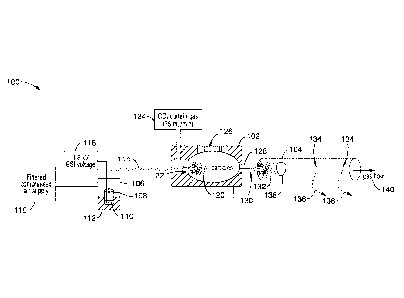
it is very common for utilities to expend significant amounts of money to
repair leaks on pipes that will ultimately be replaced.
[0009] Repair of underground pipelines generally involves exposing the
pipeline and replacing the leaking section of pipe or joint with a new section
or joint. One alternative is to essentially shrink-wrap the joint from the
outside, which still requires excavation. Moreover, it can be quite difficult
to
precisely determine the location of leaks within a network of pipes. Rather
than close down the pipeline to replace pipes that do not leak or where the
location of the leak is uncertain, the outside surfaces of pipes may be
coated with a polymeric coating such as polyurethane or other material
coating in an attempt to seal small fissures as a temporary remedy. This
strategy also requires excavation.
-2-
Date Recue/Date Received 2021-07-08
[0010] It is also very difficult to seal leaks remotely in a cost-
effective
manner. This is particularly important for low and medium pressure pipes
with a large number of joints between sections.
[0011] Accordingly, there is a need for a method of identifying and
repairing
leaks in pipeline networks that does not require excavation and does not
require normal pipeline distribution to be interrupted for any significant
amount of time. The present technology satisfies these needs and is a
significant improvement in the art.
BRIEF SUMMARY
[0012] A system and method for detecting, marking and/or sealing leaks
in
pipelines or duct networks are provided that can be used for the remote
sealing of low and medium pressure compressed-gas systems, repairing
gas leaks in aging natural-gas distribution infrastructures, as well as
sealing
leaks in duct networks.
[0013] The method produces and introduces aerosolized sealants into
the
pipe or duct network that are tailored for remote deposition at small leaks
such as pitting holes or joints. A pressure differential is created and the
aerosol particles are suspended within an air or gas stream in the pipes and
do not deposit substantially on pipe surfaces until they reach the leaks.
[0014] The leaks themselves result in small pressure drops across the
pipe's exterior, driving the aerosols into the correct location for sealing.
At
the leak site, the suspended particles leave the air stream in the interior of
the pipe and are deposited at the leak edges and then to each other until
the leaks are closed.
[0015] The aerosol particles are kept suspended in the air stream long
enough for them to reach the leaks and then leave the air stream and
impact the sides of the leaks as the stream exits the pipe leak. This is
accomplished by the right combination of duct flow, duct pressure, and
particle size. In general terms, the aerosol particles leave the airstream at
the leaks due to their velocity (created by the duct pressure) and inertia
(determined by particle size and density). The flow regime in the pipe
-3-
Date Recue/Date Received 2021-07-08
interior determines whether the particles fall out by gravity, are flung
against
the sides of the pipe by turbulence, or are kept reasonably suspended
within the airstream. The size of the particles affects both their ability to
be
transported through the pipe, and their tendency to leave the airstream at
the leaks.
[0016] One embodiment uses the preferential deposition of aerosol
marking
particles at leak sites for marking and detecting the location and size of the
leaks. In another embodiment, the marking particles will not only indicate
the site of a leak but will also seal the leak.
[0017] The sealant aerosols also cure on time frames that facilitate
adhesion and cohesion at the leak sites, but lose their surface tack over a
pre-determined period of time and/or distance into the pipe/duct network.
In one embodiment, this is accomplished by tuning particles such that they
that lose their surface tackiness (or ability to seal) prior to reaching
components that should not be sealed. In one embodiment, this is
accomplished by drying time versus residence time, or by using particles
that will not dry or stick well at the points that should not be sealed at a
distance from the point of insertion of the particles.
[0018] Aerosol particles that are not ultimately involved in the
sealing or
marking of the leaks can be captured in a filter or allowed to exit the pipes
or ducts. In one embodiment, the sealing materials that are selected may
be non-toxic to end energy consumers, so that non-deposited sealant
aerosols can safely exit the system without consequence.
[0019] In one embodiment, the process allows repairs without service
disruption by using the existing gas or air in the pipes to move the aerosol
particles through the interior of the pipe at a desired rate. The sealant
aerosol can be introduced from easily accessible entry points, and the
compressed gas will aid in carrying the material through the system. This
will allow the distribution system to be put back into service quickly. In
appropriate cases, it may be possible for the distribution system to remain
in use during the sealing process.
[0020] Control over the materials selected and the aerosol formation
-4-
Date Recue/Date Received 2021-07-08
process will determine the characteristics of the sealant particles. The
environmental conditions of the interior of the pipeline can also influence
the duration of the aerosol particle surface tack. According to one aspect of
the present technology, a method is provided where the combination of
particle size, particle tackiness, and particle drying rate versus residence
time can be controlled. A corollary to this is that the sealant can be tuned
to lose its tackiness after a certain time or distance prior to reaching the
distribution system components that should not be sealed. For example,
the formation of particles that lose their tackiness after a certain time or
distance avoids the the possibility of sealing purposeful openings such as
pilot lights or gas valves.
[0021] Monitoring of the pressure differential across the pipe or
ducts will
permit an evaluation of the progress of the sealing process as well as to
determine whether there are leaks that are too large to seal.
[0022] Control over the process parameters will produce aerosol particles
that are in the proper size range and provide a gas or air flow within the
proper flow range so that a majority of the particles remain suspended in
the interior of the pipes until the point that they encounter leaks. Moreover,
the interior pipe pressure can be maintained within the proper range such
that a substantial fraction of the particles leave the airstream and deposit
on
the leak walls as the airstream exits through the leak.
[0023] On the other hand, for marking applications the particles do
not
necessarily need to seal the leak to provide the desired results. The correct
combination of particle size, drying rate and particle residence time and
distance over velocity can be achieved to mark the site of the leak for leak
assessment and for other remedial approaches.
[0024] Another aspect of the methods is the combination of
preferential
depostion at leaks with the use of a sealant material that can be detected
either from the inside or the outside of the pipe. The sealant composition
may also include an indicator or marker material that will allow visualization
or detection of the sealant material that has been deposited. For example,
an indicator material that can be observed visually, such as a colored dye
-5-
Date Recue/Date Received 2021-07-08
solid or fiber, or observable by exposure to infra-red or ultra-violet light
such
as phosphorescent or fluorescent materials can be employed. As an
example, a gas pipeline can be injected with particles that flouresce, either
during normal operation, or after the pipeline is isolated, and then a light
and video camera can be moved through the pipe, providing a visual
depiction of the pattern of particle deposition within the pipe.
[0025] Alternatively, the particles employed can exhibit some other
characteristic that makes the leak detectable either from the inside or the
outside of the pipe. For example, the deposited particles can produce an
emission, or have a unique atomic signature that makes their location
observable from inside or outside of the pipe or duct such as by detection of
electromagnetic radiation, or MRI. For example, the particles can serve as
miniature transmitters. In another embodiment, the particles can be
detected externally by some other physical or chemical means. Still
another embodiment involves externally detecting particles that have exited
the pipe through the leaks and have been deposited on the soil surrounding
the leak site.
[0026] Further aspects of the technology will be brought out in the
following
portions of the specification, wherein the detailed description is for the
purpose of fully disclosing preferred embodiments of the technology without
placing limitations thereon.
BRIEF DESCRIPTION OF THE SEVERAL VIEWS
OF THE DRAWINGS
[0027] The technology described herein will be more fully understood
by
reference to the following drawings which are for illustrative purposes only:
[0028] FIG. 1 is a flow diagram of a method for sealing or marking
fissures
and other leaks in pipes or ducts with particles that have a tack that
diminishes over time according to one embodiment of the technology.
[0029] FIG. 2 is a schematic view of one embodiment of an aerosol
particle
generating and distributing apparatus that allows control over the
-6-
Date Recue/Date Received 2021-07-08
characteristics of the generated particles.
DETAILED DESCRIPTION
[0030] Referring more specifically to the drawings, for illustrative
purposes,
embodiments of the apparatus and methods for the remote sealing of pipes
or ducts in low and medium pressure gas systems to prevent gas leaks in
aging infrastructures such as duct systems, or compressed-air and natural-
gas distribution systems are shown. One embodiment of the technology is
described generally in FIG. 1 to illustrate the methods and an embodiment
of the apparatus is depicted generally in FIG. 2. It will be appreciated that
the methods may vary as to the specific steps and sequence and the
apparatus may vary as to structural details without departing from the basic
concepts as disclosed herein. The method steps are merely exemplary of
the order that these steps may occur. The steps may occur in any order
that is desired, such that it still performs the goals of the claimed
technology.
[0031] Turning now to FIG. 1, one method 10 for sealing pipes using
aerosolized sealants that are tailored for remote deposition within a pipe
system at small leaks such as pitting holes is shown. The method generally
uses sealant aerosols that cure on time frames that facilitate adhesion and
cohesion only at leak sites requiring sealing at selected distances from the
aerosol point of entry leaving small diameter lines or other ducts or valves
unsealed. It may even be possible for the gas distribution system to remain
in use during sealing or be put back in service quickly after the sealing
procedure. High strength adhesive materials may also be used that are
non-toxic and non-fouling at the point of end-user combustion.
[0032] At block 20 of method 10, the sealant composition is selected
and
acquired. The sealant composition may be a sealant material alone or can
be mixed with one or more solvents. The sealant composition may also
include one or more types of marker or indicator materials. The selection of
the sealant material may be influenced by the normal line pressure of the
pipe and the composition of the pipe so that the final seal is strong enough
-7-
Date Recue/Date Received 2021-07-08
to maintain the seal.
[0033] Suitable sealants can be atomized and the atomized sealant
particles can adhere to the edges of a leak and to each other to form a seal.
Preferred sealants include various compounds that can either have good
elongation properties after drying and/or can provide rigid solid seals that
can have structural properties. One example of sealants that work well is
water-based acrylic polymer sealants. Other additives include white
mineral oil, amorphous silica or titanium dioxide, each 1.0-5.0% by weight.
In one embodiment, the selected sealant is a naturally-occurring sealing
material that is carbon-based and would not foul the final end-user
combustion systems such as furnaces and appliances.
[0034] The sealant composition that is formulated at block 20 may
optionally include one or more solvents that can facilitate the aerosolization
process and produce sealant particles of a desired size or within a range of
sizes. The selection of the optional solvents that are available for use will
be influenced by the sealant that is selected and on its volatility. This
selection of sealants and solvents also allows temporal control over the
tack range of the aerosolized sealant particles. Some examples of sealant
modifications that have been shown to increase the duration of tackiness
include the addition of acetone or p-chlorobenzotrifluride, or the use of an
acrylic polymer that has no rheological fillers.
[0035] The availability of optional solvents for use will be
influenced by the
sealant that is selected and on its volatility. This selection of sealants and
solvents allows temporal control over the tack range of the aerosolized
sealant particles. Some examples of sealant modifications that have been
shown to increase the duration of tackiness include the addition of acetone
or p-chlorobenzotrifluride, or the use of an acrylic polymer that has no
rheological fillers.
[0036] Solvents can be aqueous or organic. Preferred solvents include
water, acetone and p-chlorobenzotrifluride. The characteristics of the
aerosolized sealant particles will also be influenced by the percentage of
sealant to solvent in the final sealant composition. The preferred sealant
-8-
Date Recue/Date Received 2021-07-08
compositions have roughly 20% to roughly 25% solids. In another
embodiment, the sealant composition has between approximately 10% to
approximately 35% solids. However, if the atomizer that is used is capable
of creating small particles the sealant composition can be up to
approximately 70% solids, or if very small particles are desired, as little as
approximately 5% solids can be utilized.
[0037] The sealant composition may also include an indicator or marker
material that will allow visualization or detection of the sealant material
that
has been deposited. For example, the indicator material that is part of the
sealant composition can be observed visually, such as a colored dye, solid
or fiber, or observable by exposure to infra-red or ultra-violet light such as
phosphorescent or fluorescent materials. Alternatively, the deposited
particles can produce an emission, or have a unique atomic signature that
makes their location observable from inside or outside of the pipe such as
by detection of electromagnetic radiation, or MRI.
[0038] Once the sealant and optional solvent and marker materials have
been selected for use at block 20 of FIG. 1, the section or system of pipes
are closed off so that a pressure differential can be created within the pipes
at block 30. The pressure differential that is created within the pipes
compared to the pressure outside of the pipes generates a flow of air or gas
from the interior to the exterior through the leaks in the pipes.
[0039] The preferred pressure differential across the pipe or duct is
within a
specific range of between approximately 10 Pa and approximately 10,000
Pa. A pressure differential between approximately 25 Pa and
approximately 200 Pa is also preferred and a pressure differential between
approximately 50 Pa and approximately 150 Pa is particularly preferred for
duct systems. The preferred pressure differential decreases as the size of
the particles increases.
[0040] At block 40, an aerosol of sealant particles is generated and
injected
into the pipe of a system of pipes. The sealant particles can be injected
into a pressurized pipe as at block 30 or they can be injected into the pipe
and then the pressure differential can be created thereafter. The sealant
-9-
Date Recue/Date Received 2021-07-08
particles can also be introduced at multiple locations within the pipe or duct
system.
[0041] Sealing can be performed with polydisperse aerosols with a
particle
size range from approximately 0.5 micron to 30 microns in diameter.
Injectors can also use compressed air nozzles or airless nozzles to
disperse aerosols in the interior of the pipes or ducts. The preferred
particle size depends upon the application. Smaller diameter pipes or ducts,
and longer pipes or ducts generally require smaller particle sizes. The
aerosol particles generally are reduced in size after formation as solvents
evaporate, with the size derivative depending on the rate of evaporation,
and therefore environmental conditions.
[0042] The sealant particles are formed to have an outer surface that
has a
tack that diminishes over time. By definition, tack is a propensity of a
material to adhere instantaneously to a surface with a bond of measurable
strength when it is brought in contact with the surface with very light
pressure. Tack range is defined as the period of time that the particle
surface has a tack bond state that will adhere to leak surfaces and other
particles to form a seal.
[0043] Tackiness at the time of contact of the particles at the leak
site can
be described by the adhesive and cohesive properties of the sealant.
These properties can be regulated to have desired characteristics at a
certain distance from or time from leaving the aerosol injector. The time and
distance are related by the velocity of the carrier gas in the pipe or duct.
[0044] For example, the tack range timeframe can be increased or
decreased with the proper selection of at least one solvent to go along with
the sealant material that is selected. Control over tackiness versus time
can also be exerted, in part, by controlling the humidity and temperature
during the injection period so as to control the evaporation of the solvent
from the sealant.
[0045] The surface properties of the aerosol particles can be controlled
with
the selection of sealant composition, including the presence and
concentration of solvents, as well as the range of particle sizes that are
-10-
Date Recue/Date Received 2021-07-08
produced and the environment of the interior of the pipes. Environmental
control of the area surrounding the aerosol particle generator as well as the
interior of the pipe system to be treated can include control over the
temperature, dew point, absolute humidity, relative humidity or partial
pressure alone or in combination. Control over aspects of the environment
of the pipe or duct interior or external atomization space of the particle
generator will also allow some control over the solvent evaporation and the
diameter of the sealant particles encountering the leaks. For example, the
relative humidity in the external atomization space or the interior of the
pipes is preferably controlled to be within the range of approximately 65%
RH to approximately 95% RH. The relative temperature in the pipe network
or external atomization space is preferably controlled to be within the range
of approximately 40 F and approximately 110 F.
[0046] Control of the temperature impacts the relative humidity and
therefore the evaporation rate. In another embodiment, the dew point,
absolute humidity or partial pressure are the conditions that are controlled
instead of relative humidity.
[0047] By selecting the parameters of the elements carefully, it is
possible
to temporally control the tack of the aerosol particles to have a desired
approximate duration. Aerosol particles essentially have a "tackiness"
lifespan and the particles will no longer adhere to surfaces or to each other
after a period of time. Therefore, flow control of the aerosol particles and
the temporal control over the tack of the particles will allow control over
the
distance along the length of the pipe where the particles will stick to a leak
and where the particles will not stick. In general, it is preferred to have
the
tackiness of the particles dissipate prior to putting a duct system back in
service, however, the need for this is reduced in natural gas or
compressed-air systems.
[0048] Sealant particles that have been injected flow through the pipe
at
block 50 and respond to the pressure differential and flow that is caused by
a leak and adhere to the surfaces surrounding the leak and to other
particles to form a seal overtime. Because a differential pressure has been
-11-
Date Recue/Date Received 2021-07-08
created between the pipe/duct and its surroundings, the pressurized interior
gas will flow out of any leaks through seams, joints, or any other openings.
The aerosol particles in the fog are entrained in the flow moving out through
the leaks, and leave the streamlines of that flow due to particle inertia.
Since the aerosol particles are sufficiently small to move with the air at low
acceleration rates, they are drawn to the leaks with the air. However, the
higher acceleration rates associated with the accelerated flow created by
the pressure differential maintained across the leaks causes the particles to
leave the streamlines near the leak, thereby impacting and adhering to the
leak edges and to other particles previously deposited, gradually building
up to form a seal.
[0049] Air and liquid flow rate through the nozzles can be used to
adjust the
size of the particles forming the injected aerosol. If the sealant particles
are
too big then they will be lost on the walls of the pipe or duct prior to
reaching the leaks. If the aerosol particles are too small, then the particles
will go through the leaks with the air stream and not form a seal.
[0050] At block 60, a second or third flow of sealant particles are
optionally
injected into the pipe system sequentially or in close succession to form an
aerosol with a mixture of different sized particles or different materials. In
one embodiment, the second flow of sealant particles has a mean diameter
that is less than the mean diameter of the first flow of sealant particles.
[0051] The second and third flow of sealant particles can also be
formed
from a different material than selected for the first flow of sealant
particles.
In one embodiment, the second flow is made of or includes a material such
as a marker. The third flow is a flow of the same or different type of sealant
as the first flow of particles that coats the particles of the second flow.
[0052] It can be seen that a wide variety of materials can be
aerosolized
and deposited at leak sites throughout the system of pipes that are treated.
The second or third flow of aerosol particles can include materials such as
curative agents, cross linking agents, polymers or materials with micro-
scale or nano-scale metal particles.
[0053] The pressure differential between the interior and exterior of
the pipe
-12-
Date Recue/Date Received 2021-07-08
system to be treated can be monitored throughout the process at block 70.
Monitoring of the overall or localized pressure differential over time can
indicate whether there are leaks in the pipes that are too large to seal and
the sealant can act as a marker or indicator of the location of the leak for
other remedial action. Pressure differential monitoring may also assist in
the determination of whether additional flows of sealant particles are
necessary and the size of the particles that should be used to complete or
reinforce the seal at the leak site. The pressure differential monitoring can
also be graphed and displayed. The need for an increase or decrease in
the internal pressure of the pipe system can also be assisted by pressure
differential monitoring.
[0054] Turning now to FIG. 2, an apparatus 100 for performing the
aerosol
based remote sealing of gas leaks is schematically shown. The apparatus
100, has an aerosol particle generator and injector 102 that is configured to
produce aerosol particles 130 and inject them into a pipe system 104.
[0055] Generally, leaks 134 are sealed from the interior of the pipe
104 by
releasing aerosolized particulates 130 composed of sealant materials into
the lumen of the pipe distribution system. Various techniques can be used
to produce the aerosol. However, the aerosol particle generator and
injector 102 illustrated in FIG. 2 has a particle generator section that has a
pressure chamber 106 that contains a reservoir 108 that contains the
sealant composition 110 to be atomized. The sealant reservoir 108 may sit
in a fluid bath 112. The pressure chamber 106 has a compressed gas or
air supply 116 that allows control over the pressure within the pressure
chamber 106. The air supply 116 is a 1-2 PSI filtered compressed air
supply in the embodiment shown in FIG. 2.
[0056] The pressure chamber 106 also has a voltage source 118 that is
connected to the sealant reservoir 108 and sealant composition material
110. A particle emitting tube 114 is disposed within the sealant composition
110 in the pressure chamber 106 on one end and attached to the injector
portion at the other end. A suitable particle emitting tube 114 may be a 50
pm silica capillary tube.
-13-
Date Recue/Date Received 2021-07-08
[0057] The injector portion of the particle generator and injector 102
has a
source of curtain gas 124 such as CO2 and an orifice plate 122 that
separates and moves properly sized particles 120 from the particle emitter
tube 114 through the orifice plate 122 and into the injector chamber and out
of nozzle 128. In the embodiment shown in FIG. 2, an optional heating
element 126 is provided to heat the environment in the injector chamber to
provide some control over the particle surface tack and solvent evaporation.
[0058] The characteristics of the aerosol particles 130 that are
injected by
nozzle 128 into pipe 104 are also influenced by the environment (i.e.
temperature and humidity) in the interior of the pipe 104 system which can
also be controlled with a heated or cooled carrier gas.
[0059] Accordingly, the apparatus allows control over the size and
surface
characteristics of the injected particles as well as the rate of flow of
injected
particles 132 through the interior of pipe 104. The apparatus also allows
control over the pressure differential in the pipe system so that the draw
from air/gas streams 136 from the leaks 134 to the exterior of the pipe can
be controlled. Furthermore, control over the tack surface characteristics of
the particles, the flow rate of particles 132 through the pipe 104 system and
the pressure differential will provide control over the linear distance of
treatment and will permit the pipes to be treated in sections.
[0060] When properly optimized, the sealant materials 132 will travel
innocuously through the pressurized flow-driven system, and lodge on the
edges of the leaks 134. The sealant materials will be tuned to cure on a
time scale so that they build small internal plaques 138 over the leaks that
can withstand high pressures. The particle sizes can also be tuned so that
non-depositing material will safely exit the pressurized system along with
the normal gas flow 140.
[0061] The particles can be injected in either pressurized or de-
pressurized
pipes. In one embodiment, existing pressurized gas systems may be
treated without emptying the pipes of gas. The sealant particles can
normally be introduced to the pipe interior from easily accessible entry
points, and that the existing compressed gas in the pressurized pipes will
-14-
Date Recue/Date Received 2021-07-08
aid in carrying the material through the system. The leaks themselves
result in small pressure drops across the pipe's exterior, driving the
aerosols into the correct location for sealing. Once in place, the sealing
materials will cure on time frames that are compatible with routine
maintenance crew needs. Materials can also be selected so that they are
non-toxic to end energy consumers, so that un-deposited sealant aerosols
can safely exit the system without any consequences. In one embodiment,
naturally-occurring sealing materials that are carbon-based are used so that
the unused particles in the pipes will not foul the final end-user combustion
systems such as boilers, furnaces and appliances. Hence the process can
allow pipe leak repairs without service disruption.
[0062] From the discussion above it will be appreciated that the
technology
described herein can be embodied in various ways, including the following:
[0063] 1. A method of sealing leaks in pipes or ducts, the method
comprising: (a) forming particles of a sealant, the particles having an outer
surface with a tack range that diminishes over time; (b) creating a pressure
differential between the interior and exterior of the pipes or ducts; (c)
flowing the particles through the interior of leaky pipes or ducts; and (d)
adhering sealant particles to surfaces adjacent to a leak and to other
particles to form a seal; (e) wherein sealant particles that do not form a
seal will not adhere to interior surfaces of the pipe or duct or to other
particles after a period of time or after a certain distance from the particle
injection point.
[0064] 2. The method of any preceding embodiment, further comprising:
controlling the tack range of the sealant particles by controlling the
temperature and humidity within the interior of the pipe or duct and
controlling the particle size of the sealant particles.
[0065] 3. The method of any preceding embodiment, wherein the relative
temperature in the pipe or duct is controlled within the range of 40 F to 110
F.
[0066] 4. The method of any preceding embodiment, wherein the relative
humidity in the pipe or duct is controlled within the range of 65% RH to 95%
-15-
Date Recue/Date Received 2021-07-08
RH.
[0067] 5. The method of any preceding embodiment, wherein the sealant
particles have a mean particle diameter within the range of approximately
0.5 micron to approximately 30 microns.
[0068] 6. The method of any preceding embodiment, further comprising:
controlling the rate of flow of sealant particles through the pipe or duct to
provide spatial control over which portions of the pipe or duct are sealed
and which portions are not so that intentional openings are not sealed.
[0069] 7. The method of any preceding embodiment, further comprising:
purging remaining sealant particles from the pipe or duct with a flow of
heated or cooled gas.
[0070] 8. The method of any preceding embodiment, further comprising:
monitoring the flow into and the pressure differential across the pipe or duct
to determine if there are leaks that are too large to seal and the progress of
the sealing process.
[0071] 9. The method of any preceding embodiment, wherein the pressure
differential in the pipe or duct is maintained within the range of
approximately 10 Pa to approximately 10,000 Pa.
[0072] 10. The method of any preceding embodiment, wherein the sealant
composition comprises a composition of 5% to 70% solids to solution for
aerosolization.
[0073] 11. The method of any preceding embodiment, further comprising:
formulating a sealant composition of a sealant and at least one solvent; and
aerosolizing the sealant composition to produce the sealant particles.
[0074] 12. The method of any preceding embodiment, wherein the solvent
is selected from the group of solvents consisting of water, of acetone and p-
chlorobenzotrifluride.
[0075] 13. The method of any preceding embodiment, further comprising:
formulating a sealant composition of at least one solvent, a sealant and an
indicator; and aerosolizing the sealant composition to produce the sealant
particles.
[0076] 14. The method of any preceding embodiment, wherein the
indicator
-16-
Date Recue/Date Received 2021-07-08
is selected from the group consisting of colored dyes, colored fibers,
fluorescent dyes and phosphorescent dyes, wherein the location of the
seals in the pipe or duct are identified by the indicator.
[0077] 15. The method of any preceding embodiment, further comprising:
applying of an additional layer of sealant on leaks identified by the presence
of the indicator.
[0078] 16. A method of sealing leaks in pipes or ducts, the method
comprising: (a) forming particles of a sealant and a solvent composition, the
particles having an outer surface with a tack range that diminishes over
time; (b) creating a pressure differential between the interior and exterior
of
the pipes or ducts; (c) flowing the particles through the interior of leaky
pipes or ducts; and (d) adhering sealant particles to surfaces adjacent to a
leak and to other particles to form a seal; and (e) monitoring the pressure
differential across and flow into the pipe or duct to determine if there are
leaks that are too large to seal and the progress of the sealing process; (f)
wherein sealant particles that do not form a seal will not adhere to interior
surfaces of the pipe or duct or to other particles after a period of time or
after a certain distance from the particle injection point.
[0079] 17. The method of any preceding embodiment, further comprising:
controlling the tack range of the sealant particles with a solvent of low
volatility.
[0080] 18. The method of any preceding embodiment, further comprising:
controlling the tack range of the sealant particles by controlling the
relative
humidity of the environment surrounding a source of sealant particles; and
controlling the particle size of the sealant particles.
[0081] 19. The method of any preceding embodiment, wherein the tack
range of the sealant particles is 5 minutes to 1 hour.
[0082] 20. The method of any preceding embodiment, wherein the
pressure
differential in the pipe or duct is maintained within the range of 10 Pa to
10,000 Pa.
[0083] 21. A method of marking leaks in pipes or ducts, the method
comprising: (a) formulating a sealant composition of at least one solvent, a
-17-
Date Recue/Date Received 2021-07-08
sealant and an indicator; (b) aerosolizing the sealant composition to
produce the sealant particles; (c) flowing sealant particles through the
interior of leaky pipes or ducts; (d) creating a pressure differential between
the interior and exterior of the pipes or ducts; (e) adhering sealant
particles
to surfaces adjacent to a leak and to other particles to mark a leak; (f)
detecting marked leaks with a detector.
[0084] A method of sealing leaks in at least one leaky pice or duct,
the
method comprising: (a) forming particles of a sealant, said particles having
an outer surface with a tack that diminishes over time; (b) creating a
pressure differential between the interior and exterior of the at least one
leaky pipe or duct; (c) flowing said particles through the interior of the at
least one leaky pipe or duct; (d) adhering sealant particles to surfaces
adjacent to a leak and to other particles to form a seal; (e) wherein sealant
particles that do not form a seal will not adhere to interior surfaces of the
at
least one leaky pipe or duct or to other particles after a period to time or
after a certain distance from the particle injection point.
[0085] A method of sealing leaks in at least one leaky pipe or duct,
the
method comprising: (a) forming particles of a sealant and a solvent
composition, said particles having an outer surface with a tack that
diminishes over time; (b) creating a pressure differential between the
interior and exterior of the at least one leaky pipe or duct; (c) flowing said
particles through the interior of the at least one leaky pipe or duct; (d)
adhering sealant particles to surfaces adjacent to a leak and to other
particles to form a seal; and (e) monitoring the pressure differential across
the at least one leaky pipe or duct and flow into the at least one leaky pipe
or duct to determine the progress of the sealing process; (f) wherein sealant
particles that do not form a seal will not adhere to interior surface of the
at
least one leaky pipe or duct or to other particles after a period of time or
after a certain distance from the particle injection point.
[0086] A method of marking leaks in at least one leaky pipe or duct, the
method comprising: (a) formulating a sealant composition of at least one
solvent, a sealant and an indicator; (b) aerosolizing the sealant composition
-18-
Date Recue/Date Received 2021-07-08
to produce sealant particles, said sealant particles having an outer surface
with a tack that diminishes over time; (c) flowing said sealant particles
through the interior of the at least one leaky pipe or duct; (d) creating a
pressure differential between the interior and exterior of the at least one
leaky pipe or duct; (e) adhering sealing particles to surfaces adjacent to a
leak and to other particles to mark a leak; and (f) detecting marked leaks
with a detector.
[0087] A method of sealing leaks in an enclosure, the method
comprising:
(a) forming particlese of a sealant, said particles having an outer surface
with a tack that diminishes over time; (b) creating a pressure differential
between the interior and exterior of the enclosure; (c) flowing said particles
through the interior of the enclosure; and (d) adhering sealant particles to
surfaces adjacent to a leak and to other particles to form a seal; (e) wherein
sealant particles that do not form a seal will not adhere to interior surfaces
of the enclosure or to other particles after a period of time or after a
certain
distance from the particle injection point.
[0088] A method of sealing leaks in an enclosure, the method
comprising:
(a) forming particles of a sealant and a solvent composition, said particles
having an outer surface with a tack that diminishes over time; (b) creating a
pressure differential between the interior and exterior of the enclosure; (c)
flowing said particles through the interior of the enclosure; (d) adhering
sealant particles to surfaces adjacent to a leak and to other particles to
form
a seal; and (e) monitoring the pressure differential across the enclosure and
flow into the enclosure to determine if ther are leaks that are too large to
seal and to determine the progress of the sealing process; (f) wherein
sealant particles that do not form a seal will not adhere to interior surfaces
of the enclosure or to other particles after a period of time or after a
certain
distance from the particle injection point.
[0089] A method of marking leaks in an enclosure, the method
comprising:
(a) formulating a sealant composition of at least one solvent, a sealant and
an indicator; (b) aerosolizing the sealant composition to produce sealant
particles, said sealant particles having an outer surface with a tack that
-19-
Date Recue/Date Received 2021-07-08
diminishes over time; (c) flowing said sealant particles through the interior
of the enclosure; (d) creating a pressure differential between the interior
and exterior of the enclosure; (e) adhering sealant particles to surfaces
adjacent to a leak and to other particles to mark a leak; and (f) detecting
marked leaks with a detector.
[0090] As shown in FIG. 1, at block 50, sealant particles flowing out
of
enclosure leaks adhere to surfaces adjacent to the leak as well as other
particles to form a seal. At block 70, the pressure differential of the
enclosure is optionally monitored to determine if there are leaks that are too
large to seal.
[0091] Although the description herein contains many details, these
should
not be construed as limiting the scope of the disclosure but as merely
providing illustrations of some of the presently preferred embodiments.
Therefore, it will be appreciated that the scope of the disclosure fully
encompasses other embodiments which may become obvious to those
skilled in the art.
[0092] In the claims, reference to an element in the singular is not
intended
to mean "one and only one" unless explicitly so stated, but rather "one or
more." Furthermore, no element, component, or method step in the
present disclosure is intended to be dedicated to the public regardless of
whether the element, component, or method step is explicitly recited in the
claims. No claim element herein is to be construed as a "means plus
function" element unless the element is expressly recited using the phrase
"means for". No claim element herein is to be construed as a "step plus
function" element unless the element is expressly recited using the phrase
"step for".
-20-
Date Recue/Date Received 2021-07-08