Note: Descriptions are shown in the official language in which they were submitted.
DESCRIPTION
TITLE OF INVENTION: HAULAGE VEHICLE AND TRAVEL CONTROL SYSTEM FOR
THE SAME
TECHNICAL FIELD
[0001]
This invention relates to a haulage vehicle and a travel control
system for the same and, more particularly, to travel control of an
autonomously-movable haulage vehicle used in a surface mine and the
like.
BACKGROUND ART
[0002]
A vehicle autonomously travelling without an onboard operator,
so-called unmanned ground vehicle, is known as a haulage vehicle for
carrying ore and/or earth and gravels excavated at a surface mine
and/or the like. The unmanned ground vehicle requires the
calculations of an own-vehicle position to travel autonomously. From
this perspective, known processing for own-vehicle position
calculating systems comprises inertial-navigation operation
processing using output from a GPS (Global Positioning System) and/or
an IMU (Inertial Measurement Unit) .
[0003]
Patent Literature 1 discloses, as travel control technologies
of unmanned ground vehicles using own-vehicle positions, the
1
CA 2941985 2017-11-08
configuration that sets a target vehicle speed of a unmanned ground
vehicle to be smaller than a predetermined vehicle speed as the amount
of positional departure between a target position on a pre-decided
travel route on which the unmanned ground vehicle travels and a current
position of its own vehicle becomes large.
CITATION LIST
PATENT LITERATURE
[0004]
PATENT LITERATURE 1: WO/1997/031302
SUMMARY OF INVENTION
TECHNICAL PROBLEM
[0005]
Such an own-vehicle position obtained by the position
calculating system contains the error from the actual own-vehicle
position (true value) . Therefore, if an error contained in the
own-vehicle position is not taken into account to calculate the amount
of positional departure from the target position of the unmanned
ground vehicle, the amount of positional departure between the
own-vehicle position (true value) and the target position may possibly
be estimated to be lower than an actual amount of positional departure.
This is not considered in Patent Literature 1, and the error contained
in the own-vehicle position may possibly cause the amount of
positional departure to be calculated to be extremely small, remaining
a technical problem of an inadequate setting of a target vehicle speed
2
CA 2941985 2017-11-08
in relation to the amount of positional departure.
[0006]
The present invention has been made to address the above
technical problem and an object of the present invention is to provide
a haulage vehicle capable of performing travel control allowing for
an error of an own-vehicle position obtained from a position
calculating system, and a travel control system of the haulage
vehicle.
SOLUTION TO PROBLEM
[0007]
To address the above technical problems, the present invention
provides a haulage vehicle connected to a control server implementing
fleet management over wireless lines and autonomously traveling while
taking instructions from the control server into account, the haulage
vehicle including: a position calculating device calculating an
estimated position of its own vehicle; a position range calculating
unit calculating a position range which is centered around the
estimated position and in which the haulage vehicle is present with
a predetermined expected probability; a maximum deviation amount
calculating unit calculating a maximum deviation amount indicating
a highest value among the amounts of deviations between a target route
of the haulage vehicle and each of points included in the position
range; a target vehicle-speed decision unit setting a target vehicle
speed of the haulage vehicle to be relatively low when the maximum
deviation amount is relatively large; and a target route-tracing unit
performing control for the haulage vehicle to travel along the target
3
CA 2941985 2017-11-08
route in compliance with the target vehicle speed.
[0008]
According to the present invention, when a highest value of the
amount of positional departure between the target route and a position
range having a predetermined expected probability of presence, that
is, a position in which the haulage vehicle will be present (the
maximum deviation amount) is relatively large, the target vehicle
speed can be set to be relatively low. Because of this, if a steering
angle is set, for example, in a direction toward the target route,
this increases a possibility of the haulage vehicle returning to the
target route in a shorter distance along the travel direction. Also,
even if a steering angle is set in a different direction from the
target route, the possibility of decreasing the further positional
departure from the target route is increased as compared with the
case of a fast vehicle speed.
[0009]
Further, with the present invention, in the above configuration,
when the maximum deviation amount is within a range from a minimum
return vehicle-speed adoption threshold value or higher which is a
distance threshold value for determining whether a predetermined
minimum return vehicle speed is adopted for returning to the target
route, to less than a stop determination threshold value which is
a distance threshold value for determining that returning to the
target route is impossible, the distance threshold value being higher
than the minimum return vehicle-speed adoption threshold value, the
target vehicle-speed decision unit determines that the minimum return
4
CA 2941985 2017-11-08
vehicle speed is applied as the target vehicle speed.
[0010]
According to the present invention, when, although the
returning to the target route is possible without the need to stop,
the maximum deviation amount from the target route is relatively large,
constantly travelling at the minimum return vehicle speed makes it
possible to increase the possibility of returning to the target route
in a shorter distance along the travel direction.
[0011]
Further, with the present invention, in the above configuration,
the maximum deviation amount calculating unit calculates, as the
maximum deviation amount, a distance of longest one of a plurality
of perpendicular lines drawn to the target route from a position at
which a straight line extending in parallel to the target route is
tangent to outline of the position range.
[0012]
According to the present invention, since length comparisons
among a plurality of perpendicular lines are made to calculate the
maximum deviation amount, it is possible to reduce the load on the
calculation processing for the maximum deviation amount.
[0013]
Further, with the present invention, in the above configuration,
when the maximum deviation amount is within a range from a return
vehicle-speed adoption threshold value or higher which is a distance
threshold value smaller than the minimum return vehicle-speed
adoption threshold value to less than the minimum return vehicle-speed
CA 2941985 2017-11-08
adoption threshold value, the target vehicle-speed decision unit
determines to apply, as the target vehicle speed, the return vehicle
speed obtained by multiplying either a route request vehicle speed
indicating a speed limit predetermined in map information regarding
the target route or a control request vehicle speed determined by
the control server on the basis of at least one of congestion
conditions of the target route and a mining operation efficiency of
an overall mine, whichever is a smaller vehicle-speed value, by a
weight w (0<w<1 ) reducing as the maximum deviation amount increases.
[0014]
According to the present invention, when the maximum deviation
amount is equal to or larger than the return vehicle-speed adoption
threshold value and less than the minimum return vehicle-speed
adoption threshold value, the haulage vehicle is made to travel at
a faster vehicle-speed value if the maximum deviation amount is small,
but it is made to travel at a slower vehicle-speed value if the maximum
deviation amount is large. This makes it possible to reduce the impact
of deceleration for the retuning to the target route to the extent
possible.
[0015]
Further, with the present invention, in the above configuration,
the position calculating device is a position calculating system using
Global Positioning System; and the position range calculating unit
calculates an error ellipse centered around the estimated position,
as the position range.
[0016]
6
CA 2941985 2017-11-08
This makes it possible to determine a target vehicle speed on
the basis of an error ellipse which is an expected probability
distribution of presence distinctively seen from the positional
estimation result obtained using GPS, enabling travel control
suitable for haulage vehicles using GPS.
[0017]
Furthermore, the present invention provides a haulage vehicle
connected to a control server implementing fleet management over
wireless lines and autonomously traveling while taking instructions
from the control server into account. The haulage vehicle comprises:
a travel control system that controls the haulage vehicle to travel
either at a route request vehicle speed indicating a speed limit
predetermined in map information regarding a target route or at a
control request vehicle speed determined by the control server on
the basis of congestion conditions of the target route, in a first
distance including the target route of the haulage vehicle, to travel
at a return vehicle speed showing a vehicle-speed value reduced as
the amount of positional departure from the target route increases,
when the haulage vehicle is located in a second distance range adjacent
to an outer side of the first distance range, and to travel constantly
at a minimum return vehicle speed less than the return vehicle speed
predetermined to return the haulage vehicle to the target route, when
the haulage vehicle is located in a third distance range adjacent
to an outer side of the second distance range; and a travel drive
system that drives under control by the travel control system.
[0018]
7
CA 2941985 2017-11-08
According to the present invention, the range centered around
the target route and having the possibility of traveling of the haulage
vehicle is divided into three, the first distance range, the second
distance range and the third distance range with reference to distance.
When the haulage vehicle is located in the third distance range, the
haulage vehicle can be constantly made to travel at the minimum return
vehicle speed.
[0019]
Furthermore, the present invention provides a travel control
system of a haulage vehicle installed in a haulage vehicle connected
to a control server implementing fleet management over wireless lines
and autonomously traveling on the basis of instructions from the
control server and an estimated position of its own vehicle output
by a position calculating system installed in the own vehicle. The
travel control system comprises: a position range calculating unit
calculating a position range which is centered around the estimated
position and in which the haulage vehicle is present with a
predetermined expected probability; a maximum deviation amount
calculating unit calculating a maximum deviation amount showing a
highest value among the amounts of deviations between a target route
of the haulage vehicle and each of points included in the position
range; a target vehicle-speed decision unit setting a target vehicle
speed of the haulage vehicle to be relatively low when the maximum
deviation amount is relatively large; and a target route-tracing unit
performing control for the haulage vehicle to travel along the target
route in compliance with the target vehicle speed.
8
CA 2941985 2017-11-08
[0020]
As a result, the larger the maximum value of the amount of
positional departure between a target route and a position having
the possibility of presence of a haulage vehicle (the maximum
deviation amount), the lower the target vehicle speed can be set.
Because of this, if a steering angle is set, for example, in a direction
toward the target route, this increases a possibility of the haulage
vehicle returning to the target route in a shorter distance along
the travel direction. Even if a steering angle is set in a different
direction from the target route, the possibility of decreasing the
further positional departure from the target route is increased as
compared with the case of a fast vehicle speed.
[0020a]
An embodiment provides a haulage vehicle connected to a control
server configured to implement fleet management over wireless lines,
the haulage vehicle being configured to acquire, from the control
server, travel permission response information indicating a travel
permitted segment that is set in the haulage vehicle by the control
server, set the travel permitted segment as a target route in
accordance with the travel permission response information, and
autonomously travel along the target route, comprising: a position
calculating device configured to calculate an estimated position of
its own vehicle; a position range calculating unit configured to
calculate a position range which is centered around the estimated
position and in which the haulage vehicle is present with a
predetermined expected probability; a maximum deviation amount
9
CA 2941985 2017-11-08
calculating unit configured to calculate a maximum deviation amount
indicating a highest value among the amounts of deviations between
a target route of the haulage vehicle and each of points included
in the position range; a target vehicle-speed decision unit configured
to set a target vehicle speed of the haulage vehicle to be relatively
low when the maximum deviation amount is relatively large; and a target
route-tracing unit configured to perform control for the haulage
vehicle to travel along the target route in compliance with the target
vehicle speed.
[00201o]
Another embodiment provides a travel control system of a haulage
vehicle installed in a haulage vehicle connected to a control server
configured to implement fleet management over wireless lines, the
haulage vehicle being configured to acquire, from the control server,
travel permission response information indicating a travel permitted
segment that is determined by the control server, set the travel
permitted segment as a target route in accordance with the travel
permission response information by using an estimated position of
its own vehicle output by a position calculating system installed
in the own vehicle, and autonomously travel along the target route
comprising: a position range calculating unit configured to calculate
a position range which is centered around the estimated position and
in which the haulage vehicle is present with a predetermined expected
probability; a maximum deviation amount calculating unit configured
to calculate a maximum deviation amount showing a highest value among
the amounts of deviations between a target route of the haulage vehicle
CA 2941985 2017-11-08
and each of points included in the position range; a target
vehicle-speed decision unit configured to set a target vehicle speed
of the haulage vehicle to be relatively low when the maximum deviation
amount is relatively large; and a target route-tracing unit configured
to perform control for the haulage vehicle to travel along the target
route in compliance with the target vehicle speed.
ADVANTAGEOUS EFFECT OF INVENTION
[0021]
According to the present invention, it is possible to provide
a haulage vehicle enabling travel control allowing for an error of
an own-vehicle position obtained from a position calculating system
and a travel control system of the haulage vehicle. The forgoing and
other aspects, features and advantages of the present invention are
apparent from and will be elucidated with reference to the embodiments
described hereinafter.
BRIEF DESCRIPTION OF DRAWINGS
[0022]
[Fig. 1] Fig. 1 is a diagram illustrating the schematic layout of
a mine.
[Fig. 2] Figs. 2(a) and 2(b) are hardware block diagrams of a control
server and a dump truck 20, Fig. 2(a) showing the control server and
Fig. 2(b) showing the dump truck.
[Fig. 3] Fig. 3 is a functional block diagram illustrating principal
functions of the control server.
11
CA 2941985 2017-11-08
[Fig. 4] Figs. 4(a) and 4(b) are a diagram and a table illustrating
example route data stored in the control server, Fig. 4(a) showing
a schematic representation of the route data and Fig. 4(b) showing
an example data structure of the route data.
[Fig. 5] Fig. 5 is a block diagram illustrating the functional
configuration of the dump truck 20.
[Fig. 6] Fig. 6 is an explanatory diagram illustrating the processing
for looking for a matching link.
[Fig. 7] Fig. 7 is a block diagram illustrating the functional
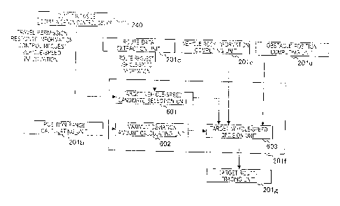
configuration of the behavior instruction unit in Fig. 5.
[Fig. 8] Fig. 8 is an explanatory diagram illustrating the processing
for calculating the maximum deviation amount.
[Fig. 9] Fig. 9 is a table showing the relationship between the maximum
deviation amount and the target vehicle speed.
[Fig. 10] Fig. 10 is a flowchart showing the flow of the travel control
processing for the damp truck in accordance with the embodiment.
[Fig. 11] Fig. 11 is a diagram illustrating a concept of another
embodiment.
DESCRIPTION OF EMBODIMENTS
[0023]
Embodiments in accordance with the present invention will now
be described with reference to the accompanying drawings. In the
following embodiments, the description may be divided into a plurality
of sections or embodiments if necessary for convenience. In the
following embodiments, if a reference is made to the number of elements
12
CA 2941985 2017-11-08
and the like (including a count, a numeric value, an amount, a range
and the like) , unless otherwise specified and limited theoretically
obviously to a specific number, and the like, the number is not limited
to the specific number and may be either equal to or greater than
or equal to or less than the specific number. It should be noted that,
in the following embodiments, unless otherwise specified and
considered definitely indispensable in theory, and the like, the
structural elements (including processing steps and the like) are
not necessarily indispensable.
[0024]
Some or all of configurations, functions, processing units and
the like in each of the following embodiments may also be implemented
as, for example, integrated circuitry, other hardware. Each of the
configurations, functions, processing units, processing units and
the like which will be described later may also be implemented as
a program running on a computer, that is, may be implemented as
software. Information in the form of a program, table, file, and/or
the like implementing each of the configurations, functions,
processing units, processing units and the like may be stored in a
storage unit such as a memory, a hard disc, SSD (Solid State Drive)
or the like, or on a storage medium such as an IC card, a SD card,
a DVD or the like.
[0025]
Embodiments in accordance with the present invention will now
be described in detail along with the accompanying drawings. It
should be noted that, throughout the drawings used to describe the
13
CA 2941985 2017-11-08
embodiments, the same or related reference signs are used to refer
to members having the same functions, and a repeated description is
omitted. Further, in the following embodiments, the same or like
portion is not repeatedly described in principle unless otherwise
required.
[0026]
First Embodiment
Described with reference to Fig. 1 is schematic layout of a mine
in which a mining dump truck (hereinafter referred to as a "dump
truck") travels as a haulage vehicle mounted with a position
calculating system in accordance with the embodiment. Fig. 1 is a
diagram illustrating the schematic layout of the mine.
[0027]
As illustrated in Fig. 1, a travel route 60 is provided in a
mine for connection between a loading site 61 (analogous to a pickup
location) and a dumping site 62 (analogous to a dumping location) .
In the loading site 61 an excavator 10, which carries out the operation
of loading earth, gravels and/or ores, carries out the excavation
operation. Then, dump trucks 20-1, 20-2 are loaded with the load such
as earth, gravels, ores and/or the like by the excavator 10 at the
loading site 61, and then travel along the travel route 60 toward
the dumping site 62. Upon arrival at the dumping site 62, the dump
trucks 20-1, 20-2 dump the load. Then, the dump trucks 20-1, 20-2
travel unloaded toward the loading site 61.
[0028]
The dump trucks 20-1, 20-2 are connected in communication with
14
CA 2941985 2017-11-08
a control server 31 installed in a control center 30 over wireless
communication lines 40. Thus, the dump trucks 20-1, 20-2 travel under
control of the control server 31. Reference sign 32 in Fig. 1 denotes
a radio antenna connected to the control server 31 and reference signs
41-1, 41-2, 41-3 denote wireless mobile stations. In the following
description, when a distinction between the dump trucks 20-1 and 20-2
is not needed, the "dump truck 20" is used.
[0029]
The dump truck 20 is equipped with a position calculating system
(not shown in Fig. 1) which receives positioning radio waves from
at least three navigation satellites 50-1, 50-2, 50-3 of GNSS (Global
Navigation Satellite System) to obtain a position of the vehicle
itself. For GNSS, GLONASS (Global Navigation Satellite System) and
GALILEO, in addition to GPS, may be employed.
[0030]
With taking into account the travel positions and target routes
of all the dump trucks 20-1, 20-2, the mining operation target, the
mining operation efficiency and the like, the control server 31
calculates (decides) a control request vehicle speed which is a
vehicle speed (scalar quantity) intended to be applied to each of
the dump trucks 20-1, 20-2 on the travel when viewed from the
perspective of the control server 31. Then, the control server 31
notifies each respective dump truck 20-1, 20-2 of the corresponding
calculation result. The control request vehicle speed is a vehicle
speed that is obtained by making correction for a speed limit in each
segment on the travel route 60 (route request vehicle speed) on the
CA 2941985 2017-11-08
basis of fleet operation conditions including the number of dump
trucks 20 during operation and an actual traffic congestion state,
the speed limit being defined in view of a curvature of a curve, a
slope gradient and a road width in map information on the travel route
60. Therefore, the route request vehicle speed is the maximum vehicle
speed in each segment, and the control request vehicle speed has a
vehicle-speed value equal to or lower than the route request vehicle
speed. It should be noted that a vehicle speed used herein is a scalar
quantity.
[0031]
Hardware configuration of the control server 31 and the dump
truck 20 in Fig. 1 will now be described with reference to Fig. 2.
Figs. 2(a) and 2(b) are hardware block diagrams of the control server31
and the dump truck 20, Fig. 2(a) showing the control server and Fig.
2(b) showing the dump truck.
[0032]
As illustrated in Fig. 2 (a) , the control server 31 comprises
a CPU 311, a RAM (Random Access Memory) 312, a ROM (Read Only Memory)
313, a HDD (Hard Disk Drive) 314, an I/F 315, and a bus 318. The CPU
311, RAM 312, ROM 313, HOD 314 and the I/F 315 are interconnected
via the bus 318.
[0033]
Further, the control server 31 is equipped with an LCD (Liquid
Crystal Display) 316 and an operating unit 317 which are connected
to the I/F 315.
[0034]
16
CA 2941985 2017-11-08
The CPU 311 is a computing unit, controlling the operation of
the overall control server 31.
[0035]
The RAM 312 is a volatile storage medium from/to which
information can be read/written at high speed, which is used as
workspace by the CPU 311 processing information.
[0036]
The ROM 313 is a read-only, nonvolatile storage medium, in which
an autonomous travel control program which is a feature of the present
invention is stored.
[0037]
The HDD 314 is a nonvolatile storage medium from/to which
information can be read/written, in which an OS (Operating System) ,
a variety of control programs, application programs and/or the like
are stored.
[0038]
The LCD 316 is a visual user interface for the user to check
the travel conditions of dump trucks20 within the mine.
[0039]
The operating unit 317 is a user interface, such as a key board,
a touch panel (not shown) overlaid on the LCD 316 and/or the like,
for the user to enter information into the control server 31.
[0040]
The I/F 315 of the control server 31 is connected to a server-side
communication device 340 for connection to the wireless communication
lines 40.
17
CA 2941985 2017-11-08
[0041]
On the other hand, as illustrated in Fig. 2(b), a dump truck
20 comprises: a travel control system 200 performing control
processing for autonomous travel; a travel drive device 210 driving
the dump truck 20 to travel, based on control instructions received
from the travel control system 200; a position calculating device
220 for calculations of an estimated position of its own vehicle of
the dump truck 20; an environmental sensor 231, such as a
millimeter-wave sensor or the like, for the recognition of environment
around the dump truck 20; a vehicle body sensor 232 used to recognize
vehicle body information about a vehicle body tilt, a carrying load
and/or the like; and a dump truck-side communication device 240 for
connection to the wireless communication lines 40.
[0042]
The travel drive device 210 comprises a braking system 211
applying brakes to the dump truck 20, a steering motor 212 for making
a change to the steering angle of the dump truck 20, and a traveling
motor 213 for traveling of the dump truck 20.
[0043]
The position calculation device 220 is a GPS or an IMU which
receives positioning radio waves from the navigation satellites 50-1,
50-2, 50-3 to calculate an estimated position of its own vehicle.
[0044]
The travel control system 200 comprises a CPU 201, a RAM 202,
a ROM 203, a HDD 204, an I/F 205 and a bus 208. The CPU 201, RAM 202,
ROM 203, HOD 204, and the I/F 205 are interconnected through the bus
18
CA 2941985 2017-11-08
208. Further, the travel drive device 210, position calculating
device 220, environmental sensor 231, vehicle body sensor 232 and
the dump truck-side communication device 290 are connected to the
I/F 205.
[0045]
In such a hardware configuration, the autonomous travel control
program stored in the ROM 203, 313, the HDD 204, 314 or a not-shown
storage medium such as an optical disc or the like is read into the
RAM 202, 312, so that the operation is effected under the control
of the CPU 201, 311. As a result, the autonomous travel control
program (software) and the hardware cooperate to form functional
blocks for implementation of the functions of the control server 31
and the travel control system 200. It should be noted that although
in the embodiment the configuration of the control server 31 and the
travel control system 200 has been described in terms of a combination
of software and hardware, the dump truck 20, in particular, may be
configured using a logic circuit to implement the functions of the
autonomous travel control program executed on the dump truck.
[0046]
The functional configuration of the control server 31 will now
be described with reference to Figs. 3 and 4. Fig. 3 is a functional
block diagram showing the principal functions of the control server31.
Fig. 4 (a) and 4 (b) are diagrams illustrating an example of the route
data stored in the control server, in which Fig. 4(a) represents
schematically the route data, and Fig. 4(b) illustrates an example
data structure of the route data.
19
CA 2941985 2017-11-08
[0047]
As illustrated in Fig. 3, the control server 31 comprises a
travel-permitted segment setting unit 311a, a control request
vehicle-speed decision unit 311b, a server-side communication control
unit 311c, a route data storage unit 314a, and a fleet management
information database (hereinafter the term "database" is abbreviated
to "DB") 314b. The travel-permitted segment setting unit 311a,
control request vehicle-speed decision unit 311b and the server-side
communication control unit 311c consist of the autonomous travel
control program executed by the control server 31.
[0048]
The route data storage unit 314a is configured using a storage
device for permanent storage such as HDD 314. As illustrated in Fig.
4(a), the route data is defined by position Information on each
respective points (hereinafter referred to as a "node") 22 on the
travel route 60 and links 21 connecting one node 22 to another. The
route data may also include topographic information regarding the
mine and absolute coordinates (3D real coordinates calculated based
on positioning radio waves) of each node 22. Each respective node
22 is assigned identification information to identify uniquely the
node 22 (hereinafter referred to as a "node ID").
[0049]
Each of the links 21 has a forward direction (the direction of
arrow A in Fig. 4(a)), in which a forward node 22 and a backward node
22 are defined. Further, as shown in Fig. 4(b), in the route data,
the identification information for unique identification of each
CA 2941985 2017-11-08
respective link (e.g., 21A) is associated with data on coordinate
values (x22A, Y22A) of the forward node ID of the link 21, coordinate
values (X22Br Y22B) of the backward node ID of the link 21, a route
request vehicle speed V21A at which a vehicle travels the link 21,
a road width W21Ar a slope gradient SnA and a curvature C21A=
[0050]
The route request vehicle speed is determined based on the road
specifications such as the slope gradient, the curvature, the road
width, etc. of the route, and/or the like. The route request vehicle
speed is a candidate for the target vehicle speed when the dump truck
20 travels actually.
[0051]
The fleet management information DB 314b stores the fleet
management information indicating a position of each respective dump
truck traveling the travel route 60.
[0052]
The travel-permitted segment setting unit 311a responds to the
travel permission request information transmitted from each dump
truck 20 to establish the subsequent travel permitted segment for
the corresponding dump truck 20. Specifically, the fleet management
information of the fleet management information DB 314b is accessed
in order to acquire positions of other dump trucks traveling ahead
of the damp truck 20. Next, the route data in the route data storage
unit 314a is accessed in order to establish a front boundary point
of a newly set travel-permitted segment at a point that is located
in the rearward direction at a distance required for the dump truck
21
CA 2941985 2017-11-08
20 to be stopped at least by applying brakes (at a stoppable distance)
from a current location of another dump truck traveling ahead of the
dump truck 20 on the travel route 60. Further, a rear boundary point
is established at a stoppable distance from a current position of
the dump truck 20. Then, the region between the front boundary point
and the rear boundary point is set as a new travel-permitted segment
to be assigned to the dump truck 20 making the travel permission
request.
[0053]
The control request vehicle-speed decision unit 311b determines
a control request vehicle speed. Specifically, the control request
vehicle-speed decision unit 311b reads the route data from the route
data storage unit 314a, and consults the fleet operation information
stored in the fleet management information DB314b, so that the control
request vehicle-speed decision unit 311b determines a control request
vehicle speed in view of a route request vehicle speed assigned to
a link contained in the new travel-permitted segment set for the dump
truck 20, a distance from another vehicle traveling ahead of the dump
truck 20, and conditions of traffic congestion. In most cases, the
maximum control request vehicle speed is a vehicle speed assigned
to a link in the route data, and in the event of traffic congestion
a vehicle speed lower than it is determined as a control request
vehicle speed. The control request vehicle speed is output to the
travel-permitted segment setting unit 311a.
[0059]
The travel-permitted segment setting unit 311a generates travel
22
CA 2941985 2017-11-08
permission response information indicating the front boundary point
and the rear boundary point of the newly set travel permitted segment
and the control request vehicle speed, and outputs it to the
server-side communication control unit 311c.
[0055]
The server-side communication control unit 311c controls
reception of travel permission request information of each dump truck
20 and transmission of the travel permission response information
generated for the request.
[0056]
The functional configuration relating to autonomous travel of
the dump truck 20 will now be described with reference to Fig. 5 to
Fig. 8. Fig. 5 is a block diagram illustrating the functional
configuration of the dump truck 20. Fig. 6 is an explanatory diagram
illustrating the processing for searching a matching link. Fig. 7
is a block diagram illustrating the functional configuration of a
behavior instruction unit in Fig. 5. Fig. 8 is an explanatory diagram
illustrating the processing of calculating the maximum amount of
deviation.
[0057]
As illustrated in Fig. 5, the travel control system 200
comprises: a route data storage unit 204a that has travel routes and
information associated with the travel route stored therein; a
position range calculating unit 201b that calculates a position range
centered around an estimated position of its own vehicle calculated
by the position calculating device 220, where the dump truck 20 is
23
CA 2941985 2017-11-08
present with an expected probability determined in advance (for
example, 95% confidence or higher) ; a route data extraction unit 201c
that extracts pertinent data from the route data storage unit 204a;
an obstacle position computing unit 201d that detects a position of
an obstacle ahead; a vehicle body information computing unit 201e
that recognizes vehicle body conditions such as a traveling vehicle
speed, a steering angle, a carrying weight and/or the like; a behavior
instruction unit 201f that outputs instruction information required
to determine a target vehicle speed of its own vehicle, a target route
and trace the target route; a target route-tracing unit 201g that
determines control variables of driving, braking and steering which
are required to move at a target vehicle speed along a target route;
a travel permission request unit 201h that, when the dump truck 20
comes near the end point (front boundary point) of the current travel
permitted segment in which the dump truck 20 is travelling, makes
a request for the setting of a new travel permitted segment for
subsequently travelling; and a dump truck-side communication control
unit 2011 that performs control for wireless communication with the
control server 31.
[0058]
The route data storage unit 204a is configured to record route
data representing the route to be travelled by the dump truck 20 as
a group of links each having points, called nodes, at both ends.
Further, in the configuration, a link ID and its accompanying
information are associated with each other, so that, upon designation
of one link, the data linked to the designated link can be extracted.
24
CA 2941985 2017-11-08
[0059]
The position range calculation unit 201b calculates a
probability distribution representing what degree of confidence is
placed in a current result of computation. In the embodiment, a GPS
is used as the position calculating device 220 and an error ellipse
is used as a probability distribution, which is reflected in the
position information to determine a position range. In the following
description, the "error ellipse" is used not only as simply a
probability distribution but also as what means a position range which
is centered around the estimated position and in which the probability
distribution of the error ellipse is reflected.
[0060]
The error ellipse represents, in the form of an ellipse, the
range in a two-dimensional plane in which its own vehicle may be
present at the time of a computation of an estimated position of its
own vehicle (that is, a measured position error) , and also represents,
in the form of a two-dimensional elliptical shape, the boundary of
the range in which the own-vehicle position is present with a certain
probability or higher, the range resulting from the merge of a presence
range with a certain probability or higher in the travel direction
of the vehicle with an presence range with a certain probability or
higher in the sideways direction of the vehicle. An estimated
position described here means a position in which there is a highest
possibility of presence of its own vehicle within the error ellipse
range, showing that the closer to the perimeter area of the error
ellipse, the possibility of presence of its own vehicle becomes lower.
CA 2941985 2017-11-08
That is, a possibility on the perimeter of the error ellipse shows
that its own vehicle may be present with a low expected probability
but with a certain probability or higher, for example, a 95%
probability or higher.
[0061]
The use of an error ellipse enables a calculation of a target
vehicle speed using an error ellipse which is a probability
distribution with a distinctive error reflected in an estimated
position obtained by using GPS, thus providing travel control suitable
for GPS-equipped dump trucks.
[0062]
The position range calculated by the position range calculating
unit 201b is output to the behavior instruction unit 201f.
[0063]
It should be noted that the probability distribution showing
an expected probability of the own-vehicle position is not limited
to the error ellipse, but may be produced as, for example, a
two-dimensional normal distribution in which a probability at some
coordinates on X, Y coordinates is plotted on the Z axis orthogonal
to the X Y plane.
[0064]
Based on the position range obtained from the position range
calculating unit 201b, the route data extraction unit 201c extracts
route data about the proximity of the position. By way of example,
the state of extraction of data about the proximity of an own-vehicle
position is shown in Fig. 7. The route data extraction unit 201c
26
CA 2941985 2017-11-08
compares an own-vehicle position CP in the position range obtained
from the position range calculating unit 201b with coordinate values
of a forward node (forward node 22A) and an backward node (e.g., 22B)
of each link (e.g., link 21A) . Then, the route data extraction unit
201c selects nearest one from the links where the own-vehicle position
CP will be located between the forward nodes 22A and the backward
nodes 22B, and determines the selection as a matching link 21A. Then,
the route data extraction unit 201c extracts route data linked to
the determined matching link 21A from the route data stored in the
route data storage unit 204a. The route data extraction unit 201c
outputs the extracted route data to the behavior instruction unit
201f.
[0065]
The obstacle position computing unit 201d performs, in
particular, calculations of the presence/absence of an obstacle
positioned ahead of the dump truck 20 in the travel direction (for
example, another vehicle ahead) and a distance from the dump truck
20 on the basis of, for example, the output of the environmental sensor
231 such as a millimeter-wave sensor, a stereocamera or the like.
When detecting some obstacle, the obstacle position computing unit
201d outputs the detection result to the behavior instruction unit
201f. Based on the detection result, the behavior instruction unit
201f effects the braking operation for deceleration or stopping in
order to avoid a collision, for example.
[0066]
The vehicle body information computing unit 201e performs the
27
CA 2941985 2017-11-08
calculations to determine values indicating the vehicle body
conditions of the dump truck 20 such as a steering angle, a traveling
speed, a carrying load and the like on the basis of the outputs from
various vehicle body sensors 232. For example, the vehicle body
information computing unit 201e performs the calculations of a
steering angle on the basis of the output from a rotation angle sensor
mounted on a steering shaft. The vehicle body information computing
unit 201e also performs the calculations of a travel vehicle speed
on the basis of the rotational speed output from a wheel rotational
speed sensor measuring a rotational speed of a front wheel and/or
rear wheel and tire specifications. Further, the vehicle body
information computing unit 201e performs the calculations of the
carrying load on the basis of the output from a pressure sensor capable
of measuring a pressure of a suspension placed in each wheel. The
vehicle body information computing unit 201e outputs the extracted
route data to the behavior instruction unit 201f. Based on the
detection result, the behavior instruction unit 201f performs the
travel control appropriate to the vehicle body information, for
example, the brakes is applied at earlier time when no load is carried
than that when a load is carried.
[0067]
The target route-tracing unit 201g is configured to perform the
control for the dump truck 20 to travel along a target route in
consonance with the target vehicle speed determined by the behavior
instruction unit 201f. The target route-tracing unit 201g comprises
a target torque producing unit 501 that generates a traveling motor
28
CA 2941985 2017-11-08
torque instruction for achieving the target vehicle speed, and a
target steering angle producing unit 502 that generates a steering
angle instruction for achieving the target route.
[0068]
The target torque producing unit 501 acquires a target vehicle
speed from the behavior instruction unit 201f, and feeds a difference
between the target vehicle speed and a value of a current vehicle
speed back in order to produce a target travel torque to reduce the
difference.
[0069]
The target steering angle producing unit 502 acquires travel
permission response information from the dump truck-side
communication control unit 201i to acquire position information on
a target route (travel permitted segment) . Then, a positional
departure between the target route and the estimated position obtained
from the position range calculating unit 201b is fed back to produce
a target steering angle to reduce the difference.
[0070]
The travel permission request unit 201h collates the estimated
own-vehicle position obtained from the position range calculating
unit 201b with the route data read from the route data storage unit
204a, and determines whether or not its own vehicle reaches the point
where travel permission request information is transmitted to make
a request to establish the subsequent travel permitted segment (travel
transmission request point) . If the vehicle has reached, the travel
permission request unit 201h transmits the travel permission request
29
CA 2941985 2017-11-08
information to the dump truck-side communication control unit 201i.
[0071]
The dump truck-side communication control unit 201i controls
transmission of the travel permission request information for a
request for the subsequent travel permitted segment to the control
server 31, and reception of travel permission response information
(including the control request vehicle-speed information) from the
control server 31.
[0072]
The behavior instruction unit 201f comprises, as illustrated
in Fig. 7, a target vehicle-speed candidate selection unit 601 that
selects one from a plurality of target vehicle-speed candidates, a
maximum deviation amount calculating unit 602 that calculates a
maximum amount of deviation having the largest value of the amounts
of deviation between the target route of the dump truck 20 and the
respective points included within the position range, and a target
vehicle-speed decision unit 603 that determines a relatively low
target vehicle speed of the haulage vehicle when the maximum amount
of deviation is relatively large.
[0073]
The target vehicle-speed candidate selection unit 601 acquires
(reads) a route request vehicle speed from the route information in
the route data linked to the matching link 21A acquired from the route
data extraction unit 201c, and also reads a control request vehicle
speed included in the travel permission response information output
from the dump truck-side communication control unit 201i. And, the
CA 2941985 2017-11-08
target vehicle-speed candidate selection unit 601 compares the two
vehicle speeds with each other to select a lower vehicle speed as
a candidate for target vehicle speeds. The target vehicle-speed
candidate selection unit 601 outputs the selected target
vehicle-speed candidate to the target vehicle-speed decision unit
603.
[0074]
As illustrated in Fig. 8, the maximum deviation amount
calculating unit 602 determines a maximum deviation amount MaxD
between the own-vehicle position CP and the matching link 21A which
is a target route on the basis of the own-vehicle position CP and
the error ellipse EE which are obtained from the position range
calculating unit 201b, the matching link 21A obtained from the route
data extraction unit 201c, and coordinates of the forward node 22A
and the backward node 225 linked to the matching link. The maximum
deviation amount MaxD is defined as a conceivable maximum amount of
departure from the matching link 21A which is a target route. The
own-vehicle position CP and the error ellipse EE are output from the
position range calculating unit 201b. This own-vehicle position CP
is a position in which there is a highest possibility of presence
in terms of probability, and a region centered around this position
where there is a possibility of presence with a certain probability
or higher is represented as an error ellipse EE. In other words, there
is a possibility that the dump truck 20 is present as long as within
the error ellipse EE. After obtaining the own-vehicle position CP
and the error ellipse EE, the maximum deviation amount calculating
31
CA 2941985 2017-11-08
unit 602 calculates a maximum deviation point P which is a point
deviating farthest from the matching link 21A which is a target route.
The maximum deviation point P can be determined as a position where
Line A extending linearly in parallel to the matching link 21A is
tangent to the outline of the error ellipse EE. The maximum deviation
amount calculating unit 602 determines that a maximum deviation amount
MaxD is a maximum value of the length (longest distance) of a maximum
deviation point perpendicular line ED which is a perpendicular line
drawn from the maximum deviation point P to the matching link 21A
which is a target route.
[0075]
The target vehicle-speed decision unit 603 determines a target
vehicle speed on the basis of the target vehicle-speed candidate
notified by the target vehicle-speed candidate selection unit 601
and the maximum deviation amount MaxD notified by the maximum
deviation amount calculating unit 602, and then outputs it to the
target route-tracing unit 201g. At this time, a correction may be
made for the target vehicle speed thus determined, on the basis of
the outputs from the obstacle position computing unit 201d and vehicle
body information computing unit 201e. If a correction has been made,
a vehicle speed slower than the determined target vehicle speed may
be applied.
[0076]
As a rule, in vehicles, as well as in autonomously traveling
dump trucks, if the steering angle is the same, as the travel vehicle
speed is lower, the amount of departure from a target route can be
32
CA 2941985 2017-11-08
reduced in a shorter distance in the travel direction. Therefore,
in order to reduce the amount of departure from a target route in
a shorter possible distance in the travel direction, a decrease in
travel vehicle speed is required. In short, the target vehicle speed
may be decreased for a decrease in travel vehicle speed.
[0077]
Here, the own-vehicle position of the dump truck 20 that has
been calculated based on the output of the position calculating device
220 as described above is present on the perimeter of the error ellipse
with a certain probability. Accordingly, for a higher degree of
safety even if the possibility is low, in the embodiment, the amount
of departure from a target route is calculated by employing a position
having a largest amount of departure from a target route in the error
ellipse (maximum deviation point) as an estimated positon of its own
vehicle used to determine a target vehicle speed.
[0078]
Given these circumstances, the target vehicle-speed decision
unit 603 makes a correction for the target vehicle-speed candidate
selected by the target vehicle-speed candidate selection unit 601
on the basis of the maximum deviation amount MaxD which is a maximum
amount of departure from a target route. Then, the target
vehicle-speed decision unit 603 outputs the corrected target vehicle
speed to the target route-tracing unit 201g. This makes it possible
to reduce the amount of deviation in a shorter distance in the travel
direction.
[0079]
33
CA 2941985 2017-11-08
Fig. 9 is a table showing the relationship between a maximum
deviation amount and a target vehicle speed. In the table in Fig.
9, when the maximum deviation amount MaxD is less than a return
vehicle-speed adoption threshold value JD1 used to make a
determination whether a return vehicle speed lower than a target
vehicle-speed candidate is adopted, a current target vehicle-speed
value is multiplied by weight w=1. Therefore, when the maximum
deviation amount MaxD is less than the return vehicle-speed adoption
threshold value JD1, the target vehicle-speed decision unit 603
multiplies the target vehicle-speed candidate by weight 1, that is,
the target vehicle-speed candidate is used as a target vehicle speed
without any change.
[0080]
When the maximum deviation amount MaxD is equal to or greater
than the return vehicle-speed adoption threshold value JD1 and less
than a minimum return vehicle-speed adoption threshold value JD2 used
to make a determination whether a predetermined minimum return vehicle
speed is adopted for a return to the target route, the target
vehicle-speed decision unit 603 multiplies the target vehicle-speed
candidate by a weight w that is reduced with an increase of the maximum
deviation amount MaxD in a range of wmin<w<1 is a
value greater
than zero and less than 1) , in order to determine a target vehicle
speed.
[0081]
When the maximum deviation amount MaxD is equal to or greater
than the minimum return vehicle-speed adoption threshold value JD2
34
CA 2941985 2017-11-08
and equal to or less than a stop determination threshold value JD3
used to make a determination that a return to the target route is
impossible, the target vehicle-speed decision unit 603 determines
that the minimum return vehicle speed is adopted as a target vehicle
speed. Asa result, even if the dump truck 20 deviates from the target
route by large amount, the dump truck 20 can return to the target
route in a short distance in the travel direction by traveling at
a sufficiently low return vehicle-speed (e.g., 5km/h). On the other
hand, if the amount of departure from the target route is relatively
small, performing the returning operation at a vehicle speed higher
than the minimum return vehicle speed makes it possible to further
decrease the effect on the deceleration of the dump truck 20 in the
returning operation.
[0082]
When the maximum deviation amount MaxD is equal to or greater
than the stop determination threshold value JD3, the target
vehicle-speed decision unit 603 determines that the amount of
deviation makes the returning impossible, and is configured to reduce
a final target vehicle speed to zero for instruction of making a stop.
[0083]
The return vehicle-speed adoption threshold value JD1, the
minimum return vehicle-speed adoption threshold value JD2 and the
stop determination threshold value JD3 as described above may be
predetermined with consideration given to external factors such as
a loading state of the vehicle, a road width, the presence/absence
of occurrence of a passing-by event and/or the like, or instead may
CA 2941985 2017-11-08
be dynamically determined in response to variations in the external
factors while the damp truck 20 is traveling.
[0084]
The flow of the travel control processing for the dump truck
in accordance with the embodiment will now be described with reference
to Fig. 10. Fig. 10 is a flow chart showing the flow of the travel
control processing for the dump truck in accordance with the
embodiment.
[0085]
For initiation of the travel control processing, first, the
engine of the dump truck 20 is started. This turns on the main power
of the travel control system 200, so that calculations of an estimated
position of its own vehicle by the position calculating device 220
are started (S1001). Alternatively, instead of the power source
connected to the engine, a power switch may be additionally provided,
which may be turned on for power on. If the destination point of the
damp truck 20 is yet to be decided (S1002/No), the travel permission
request unit 201h makes a request of the control server 31 to set
a destination point (S1003), and the control server 31 sets a
destination point and sends it to the damp truck 20 (S1004).
[0086]
If a destination point is set (S1002/Yes, S1004), the travel
permission request unit 201h reads an estimated position in the
position calculating device 220 to determine whether or not the damp
truck 20 arrives at a travel permission request point. If the arrival
is determined (S1005/Yes), a request of the control server 31 is made
36
CA 2941985 2017-11-08
to set the next travel permission request point (S1006) . The
travel-permitted segment setting unit 311a of the control server 31
sets a travel permitted segment, whereupon the control request
vehicle-speed decision unit 311b determines a control request vehicle
speed on the basis of the fleet management information and the route
request vehicle-speed contained in the route data linked to the link
in the travel permitted segment thus set. The control request
vehicle-speed decision unit 311b generates the
travel-permitted-segment response information showing the above
contents and transmits it to the dump truck 20 as a response (S1007) .
[0087]
Further, the position range calculating unit 201b calculates
a position range which is centered around the estimated position of
its own vehicle acquired from the position calculating device 220
and in which its own vehicle is present with a predetermined expected
probability (S1008) . The route data extraction unit 201c performs
a comparison between the position range and the route data in the
route data storage unit 209a, and retrieves a matching link located
closest to its own vehicle for extraction of the route data (S1009) .
[0088]
The target vehicle-speed candidate selection unit 601 performs
a comparison between the control request vehicle speed and the route
request information included in the route data on the matching link
read by the route data extraction unit 201c, and selects the lower
vehicle speed as a target vehicle-speed candidate (S1010) , outputting
it to the target vehicle-speed decision unit 603.
37
CA 2941985 2017-11-08
[0089]
The maximum deviation amount calculating unit 602 retrieves a
point located farthest from the target route (maximum deviation amount
point) on the basis of the position range calculated by the position
range calculating unit 201b, and calculates a distance between the
maximum deviation amount point and the target route (maximum deviation
amount) (S1011) , outputting it to the target vehicle-speed decision
unit 603.
[0090]
If the maximum deviation amount is less than the return
vehicle-speed adoption threshold value (S1012/Yes) , the target
vehicle-speed decision unit 603 adopts the target vehicle-speed
candidate as a target vehicle speed without any change (S1013) , which
is then output to the target route-tracing unit 201g.
[0091]
If the maximum deviation amount is equal to or greater than the
return vehicle-speed adoption threshold value and less than the
minimum return vehicle-speed adoption threshold value (51014/Yes) ,
the target vehicle-speed decision unit 603 multiplies the target
vehicle-speed candidate by a weight smaller than 1 to calculate a
return vehicle speed, and adopts it as a target vehicle speed (S1015) ,
which is then output to the target route-tracing unit 201g.
[0092]
If the maximum deviation amount is equal to or greater than the
minimum return vehicle-speed adoption threshold value and less than
the stop determination threshold value (S1016/Yes) , the target
38
CA 2941985 2017-11-08
vehicle-speed decision unit 603 adopts the minimum return vehicle
speed as a target vehicle speed (S1017) , which is then output to the
target route-tracing unit 201g.
[0093]
If the maximum deviation amount is equal to or greater than the
stop determination threshold value (S1018/Yes) , the target
vehicle-speed decision unit 603 determines that the damp truck 20
is to be stopped, which is then output to the target route-tracing
unit 201g.
[0094]
The target torque producing unit 501 of the target route-tracing
unit 201g calculates a torque to achieve the acquired target vehicle
speed and also the target steering-angle producing unit 502 references
coordinates of the front node of the matching link, and the front
boundary point and the rear boundary point of the travel permitted
segment included in the travel permission response information to
calculate a steering angle for travelling along the target route.
And, in conformance with the calculated torque and the calculated
steering angle, the drive control is performed on the travel drive
device 210 (S1019) . During the travelling, the flow returns to step
S1001 to repeat the above series of processes.
[0095]
According to the embodiment, even if the amount of departure
from a target route is large, the damp truck 20 can decrease the amount
of departure from the target route by being given a return vehicle
speed, so that there is no need to set a final target vehicle speed
39
CA 2941985 2017-11-08
to zero. However, in environments such as a mine, a significantly
large deviation from the target route increases the risks of
occurrences of events of swerving off the road and colliding with
an oncoming vehicle for the reasons of a limited road width, the
existence of an oncoming traffic lane, and the like. Given these
circumstances, the setting of the final target vehicle speed of zero
makes it possible to avoid the occurrence of such events.
[0096]
The above-illustrated embodiment should not be taken as
limiting the present invention, and various modifications may be made
without departing from the scope and sprit of the present invention.
Another embodiment is described with reference to Fig. 11. Fig. 11
is a diagram illustrating the concept of another embodiment. For
example, as shown in Fig. 11, a range including a target route and
extending for a relatively short distance from the target route (for
example, the return vehicle-speed adoption threshold value) is set
as a first distance range R1 . A range adjoining the outside of the
first distance range R1 and extending at a relatively far distance
from the target route (for example, the minimum vehicle-speed adoption
threshold value) is set as a second distance range R2. Further, a
range adjoining the outside of the second distance range R2 and
extending at a farther distance from the target route (for example,
the stop determination threshold value) is set as a third distance
range R3. The damp truck 20 may travel at the route request vehicle
speed or control request vehicle speed in a range of the first distance
range R1, may travel at the return vehicle speed in the second distance
CA 2941985 2017-11-08
range R2 and may travel constantly at the minimum return vehicle speed
in the third distance range R3. Further, the damp truck 20 may be
stopped outside the third distance range R3. Incidentally, the third
distance range R3 may be established as an open end (a range without
a specified side on the side opposite to the target route) . In this
case, the damp truck 20 travels at a constant speed without stopping
until returning to the second distance range R2.
[0097]
As a consequence, even if an estimated position comprises an
error, the damp truck 20 can be made to travel based on a comparison
between an estimated position with a highest presence possibility
and the first distance range, the second distance range, the third
distance range, enabling the travel control by absorbing an error
in a position calculation.
REFERENCE SIGNS LIST
[0098]
... Excavator
20, 20-1, 20-2 ... Dump truck
31 ... Control server
40 ... Wireless communication lines
50-1, 50-2, 50-3 ... Navigation satellite
60 ... Travel route
41
CA 2941985 2017-11-08