Note: Descriptions are shown in the official language in which they were submitted.
81799584
METHOD FOR SUPPLYING FIRE SUPPRESSING AGENT
DESCRIPTION
Related Application
[001] This application claims the benefit of priority under 35 U.S.C. 119(e)
of U.S. Provisional Application No. 61/952,503, filed March 13, 2014.
Field of the Disclosure
[002] The present disclosure relates to systems and methods for
suppressing fires. In particular, the present disclosure relates to systems
and
methods for suppressing fires associated with containers.
Background of the Disclosure
[003] Cargo may be transported to its destination using one or more of
several different types of vehicles, including, for example, ships, trains,
aircraft, and
trucks. Such cargo is transported while located in the interior of cargo
areas. In
some cases, cargo may include hazardous, easily flammable, and/or easily
combustible materials that may render transport dangerous to the cargo itself,
as
well as to the vehicle transporting the cargo and operators of the vehicle.
[004] In many instances, cargo may be carried in an area separated from an
operator controlling the vehicle. As a result, an operator may be unaware of a
fire or
explosion that has occurred within a cargo container or within the cargo area.
Moreover, due to the nature of a cargo vehicle, there may be a limited supply
of fire
suppressant available. For example, aboard a cargo aircraft, the weight of any
fire
suppressant may limit the amount of fire suppressant that may be carried for
1
Date Recue/Date Received 2021-08-26
CA 02942056 2016-09-08
WO 2015/138732
PCT/US2015/020194
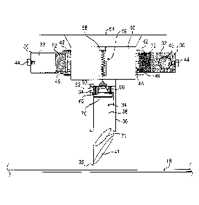
suppressing fires. Therefore, it may be desirable to limit the amount of fire
suppressant used to extinguish a fire in order to reduce the weight carried by
the
aircraft by focusing any release of fire suppressant on the particular area in
need of
fire suppressant, rather than merely releasing a large enough amount of
suppressant
to flood the entire cargo area. Furthermore, the fire suppressant itself may
be
harmful to some types of cargo. Therefore, it may be desirable to limit the
release of
fire suppressant to the location in need of fire suppression, so as to limit
the spoilage
of cargo not in need of fire suppressant.
[005] Because cargo areas experiencing a fire may be located remotely from
cargo vehicle operators (i.e., the cargo may be located in an unoccupied
and/or
difficult to access portion of the vehicle), it may be more difficult to
provide fire
suppressant to an area experiencing a fire in a timely manner. Therefore, it
may be
desirable to provide a system for supplying fire suppressant remotely and in a
timely
manner.
[006] One example of a cargo vehicle having an operator located relatively
remotely from the cargo area is an aircraft. The majority of cargo carried by
modern
aircraft is transported in cargo containers or on cargo pallets. The
containers are
generally referred to generically as Unit Load Devices ("ULDs"). For safety
considerations, ULDs must often be configured to engage an aircraft cargo
locking
system in order to restrain the cargo containers under various flight, ground
load,
and/or emergency conditions. Under federal air regulations, ULDs are
considered
aircraft appliances, are Federal Aviation Administration (FAA)-certified for a
specific
type of aircraft, and are typically manufactured to specifications contained
in National
Aerospace Standard (NAS) 3610.
2
CA 02942056 2016-09-08
WO 2015/138732
PCT/US2015/020194
[007] In the cargo aircraft example, while some cargo areas may be
conventionally equipped with fire extinguishing bottles intended for manual
operation, few cargo containers may be accessible to flight crews during a
flight,
thereby possibly rendering it difficult to manually extinguish a fire located
in an
aircraft cargo area using fire extinguishing bottles. In addition, fires may
occur inside
cargo containers, and if those fires are not suppressed or extinguished, they
may
breach the walls of the container and spread throughout the cargo area.
However, it
may be difficult, if not impossible, to suppress or extinguish a fire inside a
container
without discharging fire suppressant into the interior of the container.
[008] Thus, it may be desirable to provide a system for suppressing a fire
associated with a container for which a fire has been detected. In addition,
it may be
desirable to provide a system for supplying fire suppressant inside the
container.
Further, it may be desirable to provide a system for supplying a fire
suppressant
inside the container for an extended period of time or duration of time, for
example,
so that a cargo aircraft may safely land before a fire spreads throughout the
cargo
area.
[009] Such a fire suppression system or plurality of systems may be located
either in one area of a cargo area, such as a "high risk" area containing
particularly
hazardous materials, or throughout the cargo area.
[010] Problems associated with detecting and/or suppressing fires are not
limited to the cargo transportation industry. Similar problems may arise, for
example,
wherever cargo and/or other articles are stored in a location that is remote
from a
person supervising the cargo or other articles, such as in a storage facility.
Thus, in
a broad variety of situations, it may be desirable to remotely detect and/or
remotely
suppress a fire.
3
CA 02942056 2016-09-08
WO 2015/138732
PCT/US2015/020194
[011] In many applications, it may be impractical or inefficient to store a
fire
suppression system directly in a container such as a ULD. For instance,
containers
may be subjected to harsh environments, including extreme cold and heat,
shock,
vibration, and general abuse. As a result, providing a fire suppression system
in
each individual container may be impractical due, for example, to accelerated
degradation or failure of such systems over time. Moreover, a given company in
the
cargo freight industry may use thousands of containers, and the cost of
equipping
each container with a fire suppression system may be prohibitive. Installing,
maintaining, and removing the fire suppression system of each container could
also
be impractical and uneconomical. As a result, there are many possible
drawbacks to
providing fire suppressing systems in a large number of containers.
[012] In addition, existing technologies and techniques may only provide a
limited fire suppressing window. For example, some methods may be a one-time
solution, such as devices that supply a fire suppressing agent into a
container during
a single application. When a fire suppressing agent leaks out of or disperses
from a
ULD after introduction into the ULD, the fire may grow again and breach the
ULD,
potentially spreading to surrounding cargo. This may severely limit the time
available for a flight crew to safely land a cargo aircraft, for example. Some
tests
have shown that a single application of fire suppressing agent into a
container may
be effective for twenty minutes or less. This may be inadequate, for example,
for a
cargo aircraft during a transoceanic flight, where it may take several hours
to fly to
the closest airport suitable for landing. Therefore, it may be desirable to
provide a
consistent or repeated supply of fire suppressing agent to a container over an
extended duration.
4
CA 02942056 2016-09-08
WO 2015/138732
PCT/US2015/020194
SUMMARY
[013] In the following description, certain aspects and embodiments of a
device for supplying fire suppressing agent to the interior of a container for
an
extended duration will become evident. It should be understood that the
aspects and
embodiments, in their broadest sense, could be practiced without having one or
more features of these aspects and embodiments. It should be understood that
these aspects and embodiments are merely exemplary.
[014] One aspect of the disclosure relates to a device for supplying fire
suppressing agent to the interior of a container for an extended duration. The
device
may include a plurality of chambers configured to contain and selectively
expel fire
suppressing agent, a puncture mechanism configured to puncture a container,
and a
manifold in flow communication with the plurality of chambers and the puncture
mechanism. The device may further include a controller configured to initiate
expulsion of the fire suppressing agent from the chambers in a controlled
manner.
The device may be configured such that the fire suppressing agent may be first
expelled from a first one of the plurality of chambers at a first time, and
the fire
suppressing agent may be expelled from a second one of the plurality of
chambers
at a second time that is later than the first time.
[015] As used herein, the term "fire" is not necessarily limited to a fire
having
visible flames. Rather, the term "fire" is used in a broad sense and may be
used to
describe situations in which an object and/or surface is exhibiting a higher
temperature than desired or considered to be unsafe to a person having skill
in the
art, such as, for example, a situation in which an object and/or surface is
smoldering,
smoking, and/or is hot to the touch.
CA 02942056 2016-09-08
WO 2015/138732
PCT/US2015/020194
[016] According to another aspect, a system for supplying fire suppressing
agent to the interior of a container for an extended duration may include a
plurality of
chambers configured to contain and selectively expel fire suppressing agent, a
puncture mechanism configured to puncture a container, and a manifold in flow
communication with the plurality of chambers and the puncture mechanism. The
system may further include a sensor configured to provide signals indicative
of a
temperature associated with a container to a controller configured to initiate
expulsion of fire suppressing agent from the chambers in a controlled manner.
The
system may be configured such that the fire suppressing agent may be first
expelled
from a first one of the plurality of chambers at a first time, and the fire
suppressing
agent may be expelled from a second one of the plurality of chambers at a
second
time that is later than the first time. The puncture mechanism may be
configured to
extend and puncture a container after expulsion of the fire suppressing agent.
[017] According to a further aspect, a method for supplying fire suppressing
agent to the interior of a container for an extended duration may include
detecting
sensor signals indicative of a temperature associated with a container,
determining
via a controller that the fire suppressing agent should be supplied to the
interior of
the container based at least in part on the sensor signals, and initiating via
the
controller expulsion of fire suppressing agent from a chamber containing fire
suppressing agent. The method may further include puncturing a surface of the
container with a puncture mechanism to provide flow communication between the
chamber and the interior of the container to permit supply of fire suppressing
agent
into the interior of the container at a first time. The method may further
include
initiating, via the controller, expulsion of fire suppressing agent from a
second
chamber containing fire suppressing agent at a second time after the first
time. The
6
81799584
method may further include supplying fire suppressing agent from the second
chamber into the interior of the container.
[017a] According to another aspect of the present invention, there is
provided a device for supplying fire suppressing agent to the interior of a
container
for an extended duration, the device comprising: a plurality of chambers
configured to contain and selectively expel the fire suppressing agent; a
puncture
mechanism configured to puncture a container comprising a conveyance tube and
a puncture tip associated with the conveyance tube; a manifold in flow
communication with the plurality of chambers and the puncture mechanism; and a
controller configured to initiate expulsion of the fire suppressing agent from
the
chambers in a controlled manner, wherein the device is configured such that
the
fire suppressing agent is expelled from a first one of the plurality of
chambers at a
first time, wherein the conveyance tube and the puncture tip are configured
such
that the puncture tip translates relative to the conveyance tube away from the
manifold to puncture the container, thereby providing flow communication
between
the conveyance tube and the interior of the container, wherein the puncture
mechanism further comprises a pressure disk coupled to the puncture tip, the
pressure disk being configured to transfer force from the fire suppressing
agent
after expulsion from the chambers to the puncture tip, thereby inducing the
puncture tip to translate relative to the conveyance tube away from the
manifold,
wherein the pressure disk further comprises and emergency pressure release
valve, and wherein the device is configured such that the fire suppressing
agent is
expelled from a second one of the plurality of chambers at a second time later
than the first time.
[017b] According to still another aspect of the present invention, there is
provided a system for supplying fire suppressing agent to the interior of a
container for an extended duration, the system comprising: a plurality of
chambers
configured to contain and selectively expel the fire suppressing agent; a
puncture
mechanism configured to puncture a container comprising a conveyance tube and
a puncture tip associated with the conveyance tube; a manifold in flow
communication with the plurality of chambers and the puncture mechanism; and a
sensor configured to provide signals indicative of a temperature associated
with a
container to a controller configured to initiate expulsion of the fire
suppressing
7
Date Recue/Date Received 2021-08-26
81799584
agent from the chambers in a controlled manner, wherein the system is
configured
such that the fire suppressing agent is expelled from a first one o the
plurality of
chambers at a first time, wherein the system is configured such that the fire
suppressing agent is expelled from a second one of the plurality of chambers
at a
second time later than the first time, wherein the conveyance tube and the
puncture tip are configured such that the puncture tip translates relative to
the
conveyance tube away from the manifold to puncture the container after
expulsion
of the fire suppressing agent, thereby providing flow communication between
the
conveyance tube and the interior of the container, wherein the puncture
mechanism further comprises a pressure disk coupled to the puncture tip, the
pressure disk being configured to transfer force from the first suppressing
agent
after expulsion from the chambers to the puncture tip, thereby inducing the
puncture tip to translate relative to the conveyance tube away from the
manifold,
and wherein the pressure disk further comprises an emergency pressure release
valve.
[017c] According to yet another aspect of the present invention, there is
provided a device for supplying fire suppressing agent to the interior of a
container
for an extended duration, the device comprising: a plurality of chambers
configured to contain and selectively expel the fire suppressing agent; a
puncture
mechanism configured to puncture a container comprising a conveyance tube and
a puncture tip associated with the conveyance tube; a manifold in flow
communication with the plurality of chambers and the puncture mechanism; and a
controller configured to initiate expulsion of the fire suppressing agent from
the
chambers in a controlled manner, wherein the device is configured such that
the
fire suppressing agent is expelled from a first one of the plurality of
chambers at a
first time, wherein the conveyance tube and the puncture tip are configured
such
that the puncture tip translates relative to the conveyance tube away from the
manifold to puncture the container, thereby providing flow communication
between
the conveyance tube and the interior of the container, wherein the puncture
mechanism further comprises a pressure disk coupled to the puncture tip, the
pressure disk being configured to transfer force from the fire suppressing
agent
after expulsion from the chambers to the puncture tip, thereby inducing the
puncture tip to translate relative to the conveyance tube away from the
manifold,
7a
Date Recue/Date Received 2021-08-26
81799584
wherein the pressure disk comprises an aperture and a pressure plug received
in
the aperture, wherein the pressure plug is configured to release from the
aperture
upon extension of the puncture tip, thereby placing the manifold in flow
communication with the interior of the container, and wherein the device is
configured such that the fire suppressing agent is expelled from a second one
of
the plurality of chambers at a second time later than the first time.
[017d] According to a further aspect of the present invention, there is
provided a method for supplying fire suppressing agent to an interior of a
container for an extended duration, the method comprising: detecting sensor
signals indicative of a temperature associated with the container; determining
via
a controller that the fire suppressing agent should be supplied to the
interior of the
container based at least in part on the sensor signals; initiating via the
controller
expulsion of fire suppressing agent from a first chamber containing fire
suppressing agent via an igniter configured to receive an activation signal
from the
controller; puncturing a surface of the container with a puncture mechanism,
after
expulsion of the fire suppressing agent has been initiated, to provide flow
communication between the first chamber and the interior of the container;
displacing a pressure plug located on a pressure disk, wherein the pressure
disk
is located at an interface between the puncture mechanism and a manifold
connecting the first chamber to the puncture mechanism, wherein the pressure
plug is displaced by a pressure plug cable fastened to the manifold; supplying
the
fire suppressing agent into the interior of the container at a first time
following
displacement of the pressure plug; initiating via the controller expulsion of
fire
suppressing agent from a second chamber containing fire suppressing agent at a
second time after the first time; and supplying fire suppressing agent from
the
second chamber into the interior of the container.
[018] It is to be understood that both the foregoing general description
and the following detailed description are exemplary and explanatory only and
are
not restrictive of the invention, as claimed.
[019] The accompanying drawings, which are incorporated in and
constitute a part of this specification, illustrate several exemplary
embodiments
and together with the description, may serve to explain the principles of the
disclosure.
7b
Date Recue/Date Received 2021-08-26
81799584
BRIEF DESCRIPTION OF THE DRAWINGS
[020] Fig. 1 is a schematic, cut-away, perspective view of an exemplary
vehicle;
[021] Fig. 2 is a schematic, cut-away, front view of an exemplary
embodiment of a system for supplying fire suppressing agent to the interior of
a
container in an exemplary cargo area;
[022] Fig. 3 is a schematic, partial cut-away, top view of an exemplary
embodiment of a system for supplying fire suppressing agent to the interior of
a
container;
[023] Fig. 4 is a schematic, cut-away, top view of an exemplary
embodiment of a chamber containing a fire suppressing agent;
[024] Fig. 5 is a schematic, partial cut-away, side view of an exemplary
embodiment of a system for supplying fire suppressing agent to the interior of
a
container during operation in an initial, non-deployed configuration;
[025] Fig. 6 is a schematic, partial cut-away, side view of an exemplary
embodiment of a system for supplying fire suppressing agent to the interior of
a
container during operation in a partially-deployed configuration;
7c
Date Recue/Date Received 2021-08-26
CA 02942056 2016-09-08
WO 2015/138732
PCT/US2015/020194
[026] Fig. 7 is a schematic, partial cut-away, side view of an exemplary
embodiment of a system for supplying fire suppressing agent to the interior of
a
container during operation in a fully-deployed configuration;
[027] Fig. 8 is a schematic, partial cut-away, side view of an exemplary
embodiment of a puncture mechanism during operation with an exemplary pressure
plug removed;
[028] Fig. 9 is a schematic, partial cut-away, side view of an exemplary
embodiment of a pressure plug assembly in a non-extended configuration;
[029] Fig. 10 is a schematic, partial cut-away, side view of an exemplary
embodiment of a pressure plug assembly in a fully-extended configuration;
[030] Fig. 11 is a schematic, top view of an exemplary embodiment of a
puncture mechanism;
[031] Fig. 12 is a schematic, partial cut-away, side view of an exemplary
embodiment of a puncture mechanism during operation with an exemplary pressure
plug;
[032] Fig. 13 is a schematic, top view of an exemplary embodiment of a
removable puncture tip; and
[033] Fig. 14 is a schematic, partial cut-away, side view of an exemplary
embodiment of a removable puncture tip.
DESCRIPTION OF EXEMPLARY EMBODIMENTS
[034] Reference will now be made in detail to exemplary embodiments,
which are illustrated in the accompanying drawings. Wherever possible, the
same
reference numbers will be used throughout the drawings to refer to the same or
like
parts.
8
CA 02942056 2016-09-08
WO 2015/138732
PCT/US2015/020194
[035] Fig. 1 shows an exemplary vehicle 10 for transporting containers. The
vehicle 10 may include a body 12 defining an interior 14 of the vehicle, a
deck 16
within the body 14, the deck 16 being configured to support a plurality of
containers
18, and a ceiling 20 spaced above the deck 16.
[036] Fig. 2 is a cross-sectional view of the exemplary vehicle 10 of Fig. 1.
The vehicle 10 may include a system 22 for supplying fire suppressing agent 32
(see
Fig. 3) to the interior of a container 18 supported by the deck 16. The system
22
may be attached, for example, to the ceiling 20 above at least one location
configured to receive a container 18. The system 22 may include a sensor 24
and a
controller 26. The system 22 may further include at least two chambers 30
containing a fire suppressing agent 32, a puncture mechanism 34 with a
conveyance
tube 36 and a puncture tip 38 (see Fig. 5), and a manifold 40 connecting the
chambers 30 to the puncture mechanism 34 that allows for flow of the fire
suppressing agent 32 from a chamber 30 to the puncture mechanism 34 during
operation of the system 22. In the exemplary embodiment shown, each chamber 30
is coupled to the manifold 40, for example, via a threaded screw connection
42.
[037] The fire suppressing agent 32 may include any suitable substance or
combination of substances. For example, the fire suppressing agent 32 may
include,
for example, a pyro-propellant configured to both generate driving pressure
and
provide a fire extinguishing or fire suppressing gas or aerosol. For example,
the fire
suppressing agent 32 may include one or more of sodium azide, 5-amino
tetrazole,
potassium 5-amino tetrazole, guanidine nitrate, potassium chlorate, potassium
nitrate, potassium perchlorate, strontium nitrate, copper nitrate (basic),
copper oxide
(black), ammonium perchlorate, or a LOVA propellant. Other substances having
similar characteristics are contemplated for use as the fire suppressing agent
32.
9
CA 02942056 2016-09-08
WO 2015/138732
PCT/US2015/020194
Additionally, the fire suppressing agent 32 may employ byproducts of chemical
reactions, such as, for example, producing potassium carbonate through a
combustion reaction in the form of a finely-dispersed, micro-pulverized
aerosol.
[038] In the exemplary embodiment shown in Fig. 3, the chambers 30 are
arranged about the manifold 40 in a circumferential manner. The system 22 may
be
configured such that only a single chamber 30 discharges a fire suppressing
agent
32 into the manifold 40 at a given time. The controller 26 may be configured
to
control ignition of the fire suppressing agent 32 within each chamber 30
according to
an ignition schedule, such that fire suppressing agent 32 may be supplied to a
container 18 over an extended duration by releasing the fire suppressing agent
32
from a plurality of the chambers 30 at spaced time intervals. The activation
rate of
each chamber 30 and/or the discharge rate of fire suppressing agent 32 from
each
chamber 30 may be controlled by the controller 26. For example, the controller
26
may include a timer using fixed time intervals, a sensory input-based program,
or
any other suitable time-regulating mechanism.
[039] The sensor 24 may be configured to detect undesirably high
temperatures, such as from a fire within a container 18. The sensor 24 may be
any
suitable fire-detection mechanism, such as a thermal sensor, a smoke detector,
or
thermally sensitive materials. In some embodiments, the sensor 24 is in
communication with the controller 26, for example, via hard-wiring and/or a
wireless
communication link. In the event that the sensor 24 detects a fire, such as
through
an elevated temperature reading or by detecting smoke, the sensor 24 is
configured
to send a signal detectable by the controller 26.
[040] The controller 26 may include one or more processors,
microprocessors, central processing units, on-board computers, electronic
control
CA 02942056 2016-09-08
WO 2015/138732
PCT/US2015/020194
modules, and/or any other computing and control devices known to those skilled
in
the art. The controller 26 may be configured to run one or more software
programs
or applications stored in a memory location, read from a computer-readable
medium,
and/or accessed from an external device operatively coupled to the controller
26 by
any suitable communications network.
[041] After receiving the signal from the sensor 24, the controller 26 may use
any suitable means, such as software programming, mechanical components, or
chemical reactions, to initiate operation of the system 22. Initiating
operation may be
accomplished, for example, via sending an activation signal to an igniter 44
located
within a chamber 30 containing the fire suppressing agent 32, for example, as
shown
in Fig. 4. When exposed to heat from the igniter 44, the fire suppressing
agent 32
may undergo a chemical reaction, rapidly expanding and increasing pressure
within
the chamber 30. According to some embodiments, following activation of the
igniter
44, the controller 26 sends a signal to a reporting unit (not shown) notifying
a user
that the system is operating, such as to a remote flight crew within an
aircraft cockpit.
It is contemplated that other mechanisms and methods may be used to trigger
release of fire suppressing agent 32.
[042] Fig. 5 shows an exemplary system 22 immediately following activation.
Following activation of the igniter 44, which may provide, for example, an
igniter
flame 45 in the chamber, the fire suppressing agent 32 heats and expands
within the
chamber 30. One or more pressure control plugs 46 located in a passage 48
between the chamber 30 and the manifold 40 may be displaced, dislodged, or
otherwise removed by pressure from the expanding fire suppressing agent 32.
(To
illustrate the presence and flow of the expanding fire suppressing agent 32, a
darker
shade is used in Figs. 5-7 for the activated fire suppressing agent 32 than
for
11
CA 02942056 2016-09-08
WO 2015/138732
PCT/US2015/020194
unactivated fire suppressing agent 33 in an unactivated chamber 30). The
pressure
control plug 46 may be formed from any suitable material as long as it
prevents
external pressure and heat from affecting an inactive chamber 30 (i.e., while
the
system is not activated). As shown in Fig. 6, once a pressure control plug 46
is
dislodged, the chamber 30 may be placed in flow communication with the
manifold
40, and the fire suppressing agent 32 may flow out of the chamber 30 and into
the
manifold 40. The fire suppressing agent 32 may continue to expand while
pressurizing the interior space of the manifold 40.
[043] Fig. 6 shows the fire suppressing agent 32 as it expands within the
manifold 40, further exerting force upon a pressure disk 50 located at the
interface
between the manifold 40 and the puncture mechanism 34. (Arrows are used in
Figs.
6-8 to schematically indicate the flow of the fire suppressing agent 32.) The
force
exerted upon the pressure disk 50 may cause the puncture tip 38, initially
located in
a retracted position within a conveyance tube 36 of the puncture mechanism 34,
to
extend along the conveyance tube 36. The puncture tip 38 may include an angled
piercing edge 39, a puncture tip opening 41, and a puncture tip side port 71.
The
puncture tip 38 may extend to a certain point, such as until the puncture tip
38
reaches one or more guide stops (not shown) on the conveyance tube 36. When
the
puncture tip 38 strikes the container 18, pressure may continue to build up on
the
pressure disk 50 as a result of the expanding fire suppressing agent 32, which
may
increase the force upon the puncture tip 38 through the pressure disk 50,
thereby
causing the puncture tip 38 to penetrate an exterior wall of a container 18.
[044] In some embodiments, the conveyance tube 36 further includes a
locking mechanism (not shown) that locks the puncture tip 38 at its furthest-
traveled
position, thereby preventing the puncture tip 38 from contacting an object and
12
CA 02942056 2016-09-08
WO 2015/138732
PCT/US2015/020194
bouncing back into the conveyance tube 36. The locking mechanism maximizes the
likelihood of successful container 18 penetration, minimizing the possible
waste of
fire suppressing agent 32 during operation of the system 22.
[045] As shown in Figs. 7 and 8, as the puncture tip 38 translates along the
extent of the conveyance tube 36, but before the puncture tip 38 reaches its
maximum extension, a pressure plug 52 located on the pressure disk 50 may be
displaced by a pressure plug cable 54 fastened to the interior of the manifold
40.
Displacement of the pressure plug 52 exposes an orifice 56 within the pressure
disk
50 that allows the fire suppressing agent 32 to flow from the manifold 40 to
the
conveyance tube 36 through the orifice 56. The puncture tip 38 penetrates the
skin
of a container 18 before the pressure plug 52 is displaced from the pressure
disk 50,
thereby allowing the fire suppressing agent 32 to flow through the conveyance
tube
36 and into the interior of the container 18 through the puncture tip opening
41
and/or the puncture tip side port 71. (The flow of fire suppressing agent 32
through
the conveyance tube 36 is shown with schematic arrows in Fig. 8).
[046] In the exemplary embodiment shown in Fig. 9, the pressure plug cable
54 may be initially coiled within a pressure plug cable sleeve 58 located
within the
manifold 40. The pressure plug cable sleeve 58 protects the pressure plug
cable 54
from damage or deformation during the initial expansion of the fire
suppressing
agent 32 within the manifold 40. The pressure plug 52 is displaced by the
pressure
plug cable 54 when the pressure plug cable 54 reaches its full extension, such
as
when the puncture tip 38 translates within the conveyance tube 36 away from
the
manifold 40 to a certain distance from the manifold 40. An exemplary
embodiment
of a fully-extended pressure plug cable 54 attached to a pressure plug 52 is
shown in
Fig. 10. The pressure plug cable 54 may be made of any suitable material, such
as
13
CA 02942056 2016-09-08
WO 2015/138732
PCT/US2015/020194
stainless steel or other materials having similar characteristics.
Collectively, the
pressure plug 52, pressure plug cable 54, and pressure plug cable sleeve 58
form a
pressure plug assembly 59.
[047] Pressure may mount within the manifold 40 and/or chamber 30 if the
puncture tip 38 does not translate far enough within the conveyance tube 36 to
displace the pressure plug 52 from the pressure disk 50 via the pressure plug
cable
54. To alleviate such pressure before it causes damage to the manifold 40
and/or
chamber 30, the pressure disk 50 may further include an emergency pressure
release valve 60.
[048] In the exemplary embodiments shown in Figs. 11 and 12, the
emergency pressure release valve 60 on the pressure disk 50 may include a
pressure plate 62, springs 64, and ports 66. The ports 66 of the emergency
pressure valve 60 may allow the fire suppressing agent 32 to bypass the
orifice 56
that would otherwise be exposed by displacement of the pressure plug 52, and
the
fire suppressing agent 32, through the ports 66, may then exert pressure upon
the
pressure plate 62. In the exemplary embodiments shown, the pressure plate 62
is
connected to the pressure disk 50 by springs 64, and includes a pressure plate
orifice 68 in the center of the pressure plate 62 configured to allow the fire
suppressing agent 32 to flow through the pressure plate 62 without impediment
upon
removal of the pressure plug 52 by the pressure plug cable 54. The pressure
plate
62 may block the flow of any fire suppressing agent 32 traveling through the
ports 66
if the pressure plug 52 remains in place, however, until the pressure from the
fire
suppressing agent 32 in the ports 66 directed against the pressure plate 62
exerts
sufficient force to displace the pressure plate 52.
14
CA 02942056 2016-09-08
WO 2015/138732
PCT/US2015/020194
[049] The strength of the springs 64, which dictates the force required for
displacement of the pressure plate 62, may be determined, for example, by
considering the critical system pressure and a factor of safety, and may be
selected
to permit the pressure plate 62 to separate from the pressure disk 50 prior to
any
pressure damage occurring to the manifold 40 or chambers 30. In the exemplary
embodiment shown in Fig. 12, when the fire suppressing agent 32 within the
manifold 40 exerts sufficient pressure against the pressure plate 62 and
stretches
the springs 64, thereby displacing the pressure plate 62, the fire suppressing
agent
32 enters the conveyance tube 36 through the pressure plate orifice 68, even
if the
puncture tip 38 is not fully extended. (The flow of the fire suppressing agent
32 is
schematically shown with arrows). The use of springs 64 is exemplary, and the
pressure plate 62 may be displaced by alternative mechanisms, such as valves
or
electrical pressure transducers (not shown).
[050] In the exemplary embodiments shown in Figs. 13 and 14, the puncture
mechanism 34 may further include a puncture tip disconnect 70 that allows for
easy
removal of the puncture tip 38 from the conveyance tube 36 after operation of
the
system 22. The puncture tip disconnect 70 may allow the puncture tip 38, for
example, to remain in the container 18 following penetration of the container
18 until
the puncture tip 38 can be safely removed during inspection.
[051] The system 22 may further include a heat sink 72 configured to cool
the fire suppressing agent 32 after ignition and before the fire suppressing
agent 32
enters one or more of the manifold 40, puncture mechanism 34, and container
18.
The heat sink 72 may be formed from any suitable material in an arrangement
with
high surface area and high thermal conductivity, such as, for example, a
series of
CA 02942056 2016-09-08
WO 2015/138732
PCT/US2015/020194
baffles or an array of fins. The heat sink 72 may be provided in one or more
of the
chamber 30, manifold 40, or conveyance tube 36.
[052] Other embodiments of the invention will be apparent to those skilled in
the art from consideration of the specification and practice of the invention
disclosed
herein. It is intended that the specification and examples be considered as
exemplary only, with a true scope and spirit of the invention being indicated
by the
following claims.
16