Note: Descriptions are shown in the official language in which they were submitted.
CA 02942309 2016-09-19
NAVIGATION DEVICE
TECHNICAL FIELD
[0001] The
present invention relates generally to navigation technologies and,
more particularly, to GNSS-based navigation devices.
BACKGROUND
[0002] Global
navigation satellite system (GNSS) technologies, such as the
Global Positioning System (GPS), capture radiofrequency signals transmitted by
orbiting GNSS satellites to provide location information. GNSS-based
navigation
technologies are increasingly found in automobiles and smart phones.
[0003] These
navigation devices, whether in-vehicle navigation devices or
navigation-capable smart phones, are typically pre-loaded with digital map
data or,
alternatively, have the ability to download digital map data over a cellular
data
network. In some
circumstances, however, the physical surroundings make it
difficult for a user of the navigation device to determine which direction to
take to
follow the navigation instructions. This is particularly true of handheld
devices being
used in the wilderness, at night, in bad weather, or in places where there are
no
easily identifiable landmarks.
[0004]
Accordingly, it would be highly desirable to provide a navigation device
that facilitates navigation in these circumstances.
SUMMARY
[0005] The
following presents a simplified summary of some aspects or
embodiments of the invention in order to provide a basic understanding of the
invention. This summary is not an extensive overview of the invention. It is
not
intended to identify key or critical elements of the invention or to delineate
the scope
of the invention. Its sole purpose is to present some embodiments of the
invention in
a simplified form as a prelude to the more detailed description that is
presented
later.
- 1 -
CA 02942309 2016-09-19
[0006] In general, the present invention provides a navigation device that
emits a
laser beam in a direction toward a destination location so as to facilitate
GNSS-
based navigation.
[0007] In accordance with one inventive aspect of the present disclosure, a
navigation device includes a user interface for receiving input specifying a
destination location, a memory for storing the destination location and for
storing
map data, a global navigation satellite system (GNSS) receiver for determining
a
current location of the navigation device, a compass for determining an
orientation,
a processor for computing a route from the current location to the destination
location and for computing, using the orientation, a direction toward the
destination
location, and a laser for emitting a laser beam in the direction.
[0008] In accordance with another inventive aspect of the present
disclosure, a
method of navigation using a navigation device entails receiving input via a
user
interface for specifying a destination location, storing in a memory the
destination
location and map data, determining a current location of the navigation device
using
a global navigation satellite system (GNSS) receiver, and determining an
orientation
using a compass. The method further entails computing, using a processor, a
route
from the current location to the destination location and computing, using the
orientation, a direction toward the destination location. The method further
entails
emitting a laser beam in the direction.
BRIEF DESCRIPTION OF THE DRAWINGS
[0009] Further features and advantages of the present technology will
become
apparent from the following detailed description, taken in combination with
the
appended drawings, in which:
[0010] FIG. 1 is a schematic depiction of a navigation device in accordance
with
one embodiment of the present invention.
[0011] FIG. 2 depicts an example of a navigation device emitting a laser
pointing
in a direction of navigation.
- 2 -
CA 02942309 2016-09-19
[0012] FIG. 3
depicts an example of a navigation device providing visual, audible
and vibratory cues that the orientation of the device matches a direction of
navigation.
[0013] FIG. 4
is a flowchart outlining a method of navigating using the navigation
device.
[0014] FIG. 5
is a flowchart of a more detailed implementation of the method in
accordance with one embodiment.
[0015] It will
be noted that throughout the appended drawings, like features are
identified by like reference numerals.
DETAILED DESCRIPTION
[0016] In
general, the present invention provides a navigation device that points
in a direction toward a destination location. Exemplary embodiments of this
invention are illustrated in the figures and described below. It will be
appreciated
that the invention may include other embodiments and variants that implement
the
inventive concept.
[0017] In the
embodiment illustrated by way of example in FIG. 1, a navigation
device generally designed by reference numeral 10. For the
purposes of this
specification, the expression "navigation device" shall be construed broadly
to mean
any handheld device, such as a pointer, portable computer, computing device,
wireless communications device, smart phone, mobile communication device,
personal digital assistant, portable media player, portable navigation device,
personal navigation device, tablet, phablet, or any other navigation-capable
device
that includes the hardware necessary to indicate a direction using a laser or
laser-
like beam of light. In one embodiment, the device resembles a pen or pointer
that
can be easily carried in the pocket of the user. In another embodiment, the
navigation device is a component in adventure video camera system. In this
embodiment, if the user of the adventure video camera system becomes lost or
disoriented, the user can engage the navigation device to locate a route back
to a
marked destination. Although the navigation device is primarily intended to be
portable or handheld, it will be appreciate that the navigation device may be
- 3 -
CA 02942309 2016-09-19
=
mounted to a vehicle or boat, or integrated within a vehicle or boat to
facilitate
vehicle-based navigation. It will also be appreciated that the expression
"navigation
device" is meant to include any combination of hardware components or
subsystems that are connected together to form the navigation device.
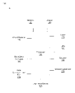
[0018]
In the embodiment illustrated by way of example in FIG. 1, the navigation
device which is generally designed by reference numeral 100 includes a
processor
110. The processor 110 may be a microprocessor or a microcontroller or a
plurality
of microprocessors or microcontrollers. The microprocessors may be dual-core
processors, multi-core processors, etc. The processor may be a central
processing
unit (CPU). The processor 110 is configured to receive, process and output
data.
The processor 110 is configured to execute a navigation application that
displays a
route to a destination location on a map. The processor 110 in the navigation
device 100 is configured to compute the route from the current location to a
destination location. The processor 110 is also configured to compute, using
an
orientation from a compass, a direction toward the destination location, as
will be
explained in greater detail below.
[0019]
The navigation device 100 includes a memory 120 that is operatively
coupled via a data bus to the processor 110. The memory 120 may include
volatile
and non-volatile memory. Volatile memory may include random access memory
(RAM), DRAM, DDR SDRAM, SRAM, or equivalent. Non-volatile memory may
include read-only memory (ROM), Mask ROM, PROM, EPROM, EEPROM,
NVRAM, Flash memory, Solid-state storage, nvSRAM, FeRAM, MRAM, PRAM or
equivalent. Memory may also include magnetic tape, hard disk drive, optical
disc
drive, or any other suitable data-storage device or medium.
The memory 120
stores the navigation application and digital map data along with label data
for labels
for street names, cities, bodies of water, landmarks, points of interest, etc.
[0020]
In the embodiment illustrated by way of example in FIG. 1, the navigation
device 100 includes a user input device 130, which may include a push-button,
keyboard, mouse, touch-sensitive display, speech-recognition module, etc.
enabling
a user of the navigation device to provide input to the navigation device. The
user
may use the user input device 130 to enter a destination location by manually
entering an address or location coordinates or by selecting a pre-loaded
location,
- 4 -
CA 02942309 2016-09-19
,
POI or address book location. The user input device 130 may be used to mark a
specific location, select one of a plurality of suggested routes proposed by
the
navigation application, to configure the navigation application, or to perform
other
navigation-related tasks.
[0021] In the embodiment illustrated by way of example in FIG. 1, the
navigation
device 100 optionally includes a display 140 which may use any suitable
display
technologies, e.g. LCD, LED, OLED, etc. The display may be a touch-sensitive
display screen. The display 140 receives displayable data from the processor
and
displays this data onscreen. The display 140 displays the digital maps, labels
for
street names, cities, bodies of water, landmarks, points of interest, etc. The
display
also displays icons or symbols representing the current location and the
destination
location as well as any waypoints along the route. The route may be displayed
in a
distinct colour on the map. The display also presents arrows, cues or other
information to facilitate navigation.
[0022] In the embodiment illustrated by way of example in FIG. 1, the
navigation
device 100 includes a global navigation satellite system (GNSS) receiver
(chip) 150
such as, for example, a Global Positioning System (GPS) receiver. The GNSS
receiver 150 has an integrated antenna to receive radiofrequency signals from
orbiting GNSS satellites from which location coordinates are determined by the
GNSS receiver 150. The GNSS receiver 150 supplies location data to the
navigation application executing on the processor 110. References herein to
"GNSS" or "GPS" are meant to include Assisted GNSS/GPS and Aided GNSS/GPS.
GNSS includes not only GPS but other satellite-based systems used around the
world including the Beidou (COMPASS) system being developed by China, the
multi-national Galileo system being developed by the European Union, in
collaboration with China, Israel, India, Morocco, Saudi Arabia and South
Korea,
Russia's GLONASS system, India's proposed Regional Navigational Satellite
System (IRNSS), and Japan's proposed QZSS regional system.
[0023] In the embodiment illustrated by way of example in FIG. 1, the
navigation
device 100 also includes a compass 160, e.g. a solid state compass. The solid
state compass includes a magnetometer for providing an orientation, i.e. a
compass
- 5 -
CA 02942309 2016-09-19
heading or bearing (which is herein referred to as the orientation). The solid
state
compass may include one or more accelerometers or gyros.
[0024] In the embodiment illustrated by way of example in FIG. 1, the
navigation
device 100 includes a laser 170 or any equivalent laser-like emitter for
emitting a
laser beam or other highly collimated ("laser-like") beam of light. The laser
emits a
beam of light in the direction to be traveled so as to visually guide the user
in the
correct direction. The laser may be configured to remain on permanently, for a
prescribed period of time, to blink, change colour, or to provide any desired
optical
effect. The processor may be configured to re-activate the laser if the user
veers
off-course.
[0025] In the embodiment illustrated by way of example in FIG. 1, the
navigation
device 100 optionally includes a light 180, e.g. an LED light, that
illuminates to
signify or indicate that the navigation device is oriented in the correct
direction. In
another embodiment, a visual cue may be provided onscreen, e.g. by a visual
display, alert, notification or the like presented on the display of the
device.
[0026] In the embodiment illustrated by way of example in FIG. 1, the
navigation
device 100 optionally includes a speaker 190 to produce a sound to signify or
indicate that the navigation device is oriented in the correct direction. The
sound
may include any suitable chime, buzz, or audible notification including spoken
alerts.
[0027] In the embodiment illustrated by way of example in FIG. 1, the
navigation
device 100 optionally includes a vibration generator 200 that vibrates to
signify or
indicate that the navigation device is oriented in the correct direction.
[0028] The navigation device 100 may optionally include the light, speaker
and
vibration generator to provide all three or any subset of these alerts to the
user.
[0029] The navigation device 100 may be user-configurable, e.g. via a
settings
or preferences page, to activate or deactivate the visual, audible and
vibratory
alerts.
[0030] In the embodiment illustrated by way of example in FIG. 1, the
navigation
device 100 includes a data communication port 210, which may be a wireless
- 6 -
CA 02942309 2016-09-19
interface for receiving map data over the air. The data communication port may
be
cellular transceiver, satellite transceiver, Wi-Fi transceiver, Bluetooth
transceiver,
or any other suitable wireless transceiver. The data communication port 210
may
also be used to receive map data updates, software updates, etc.
[0031] FIG. 2 shows by way of example a navigation device 100 in the form
of a
handheld mobile communication device having a laser 170 (held in place by a
laser
holder) that is attached to the bottom of the handheld mobile communication
device.
The laser holder may have a data connection to receive a drive signal from the
processor and a power connection to receive power from the battery of the
handheld
mobile communication device. In addition to any navigation instructions and
map
presented on the display 140, the laser 170 emits a laser beam to indicate the
direction for the user to take toward the destination location. It will be
appreciated
that if the route calculated by the navigation application is not a straight-
line route,
the laser will point in the direction for the user to take in order to
complete the first
leg of the journey. In other words, a route may comprise a sequence of route
segments defined by a series of waypoints. For such a route, the laser will
point
toward the first waypoint of the route. Upon arrival at the first waypoint,
the laser will
point toward the second waypoint of the route. Upon arrival at the second
waypoint,
the laser will point toward the third waypoint. This process will be repeated
until the
final waypoint is the destination location. Thus, the laser will point the
user in the
direction to travel so as to guide the user incrementally toward the
destination
location.
[0032] FIG. 3 depicts another embodiment in which the navigation device
provide visual, audible or vibratory cues to the user when the navigation
device is
properly aligned (oriented) with the direction to be taken. In other words, if
the
compass of the navigation device indicates that the heading (orientation)
matches
the direction required by the navigation application, then the navigation
device can
notify the user visually, audibly or tactilely. In FIG. 3, the navigation
device 100
provide a visual cue 310 by displaying a light onscreen. Alternatively, the
light may
be an LED light outside of the screen. In FIG. 3, the navigation device also
provides
tactile feedback 320 in the form of a vibration. In FIG. 3, the navigation
device 100
also provide audible notification 330 by producing a sound (e.g. chime, bell,
buzz,
- 7 -
CA 02942309 2016-09-19
etc.) or by providing spoken confirmation. The angular tolerance of the
navigation
device may be preset or user-reconfigurable to permit some minor variance
between
the compass reading and the desired direction.
[0033] Another aspect of the invention is a method of navigating using a
navigation device. As outlined in FIG. 4, the method 400 entails a step 410 of
receiving input via a user interface for specifying a destination location, a
step 420 of
storing in a memory the destination location and/or map data, and a step 430
of
determining a current location of the navigation device using a global
navigation
satellite system (GNSS) receiver. As depicted in FIG. 4, the method 400
further
entails a step 440 of determining an orientation using a compass and a step
450 of
computing, using a processor, a route from the current location to the
destination
location and computing, using the orientation, a direction toward the
destination
location. The method 400 concludes with a step 460 of emitting a laser beam in
the
direction.
[0034] In one implementation of this method, there is a further step of
vibrating a
vibration generator in response to a signal from the processor when the
processor
determines that the orientation of the compass corresponds to the direction.
[0035] In another implementation of this method, there is a further step of
illuminating a light coupled in response to a signal from the processor when
the
processor determines that the orientation of the compass corresponds to the
direction.
[0036] In another implementation of this method, there is a further step of
producing a sound in response to a signal from the processor when the
processor
determines that the orientation of the compass corresponds to the direction.
[0037] These steps (or acts or operations) may be performed in the sequence
described above or in the a different suitable sequence. In other
implementations
some of these steps may overlap or partially overlap some of the other steps.
[0038] FIG. 5 depicts a more detailed implementation of the navigation
method
introduced in FIG. 4. The method 500 shown in FIG. 5 entails a start step 502,
a
step 504 of monitoring request inputs, a decision 506 is made as to whether a
- 8 -
CA 02942309 2016-09-19
request has been made. If a request has been made, a further decision 508 is
made as to whether the request is a navigation request. If the request is not
a
navigation request, the "home" position is acquired using the GNSS receiver
(step
509) and stored in the memory of the device (step 509a). The method 500 then
proceeds to step 514 in which the heading to the "home" position is
calculated.
[0039] As shown in FIG. 5, if the request is not a navigation request
(referring to
decision 508), the device then determines (at decision 510) if a "home"
position is
stored in memory. The "home position" may be the destination location. If yes,
the
current position is acquired using the GNSS receiver at step 512. At step 514,
the
heading is calculated using the current position and the "home" position. At
step
516, the current heading is read from the compass. At decision 518, the device
determines if the calculated heading matches the current heading. If no, the
method
cycles back to step 516. If yes, the primary and/or secondary outputs are
enabled
at step 520 (i.e. the laser, light, speaker, vibration generator) to signify
that the
heading is correct. A timer is started at step 522. At step 524, the device
determines if the timer has elapsed. If no, the method cycles back to step
524. If
yes, the primary and secondary outputs are disabled at step 526. The method
continues at step 528 in which the current position is acquired using the GNSS
receiver. At step 530, the separation distance between the "home" position and
the
current position is calculated. If the device determines at decision 532 that
the
separation distance is less than a predetermined value n, the method concludes
by
enabling the arrival alarm with the primary and secondary outputs at step 534.
Navigation thus ends, i.e. the method stops at step 536. If the separation
distance
is not less than the predetermined value n, the method proceeds by returning
to step
504.
[0040] As further shown in FIG. 5, if the device determines (at decision
506) that
no request has been made, the device determines (at decision 505) whether the
device is in navigation mode. If yes, the method proceeds to step 528. If no,
the
method proceeds to step 504, as shown in the flowchart.
[0041] All or parts of the methods described above may be implemented in
software, hardware, firmware or any suitable combination thereof. Software
implementations of any part of the methods may be performed by computer-
- 9 -1k
CA 02942309 2016-09-19
readable code stored on a computer-readable medium. The computer-readable
medium can be any means that contain, store, communicate, propagate or
transport
the program for use by or in connection with the instruction execution system,
apparatus or device. The computer-readable medium may be electronic, magnetic,
optical, electromagnetic, infrared or any semiconductor system or device. For
example, computer executable code to perform the methods disclosed herein may
be tangibly recorded on a non-transitory computer-readable medium including,
but
not limited to, a CD-ROM, DVD, RAM, ROM, EPROM, Flash Memory or any
suitable memory card, etc. The method may also be implemented in hardware. A
hardware implementation might employ discrete logic circuits having logic
gates for
implementing logic functions on data signals, an application-specific
integrated
circuit (ASIC) having appropriate combinational logic gates, a programmable
gate
array (PGA), a field programmable gate array (FPGA), etc.
[0042] It is to be understood that the singular forms "a", "an" and "the"
include
plural referents unless the context clearly dictates otherwise. Thus, for
example,
reference to "a device" includes reference to one or more of such devices,
i.e. that
there is at least one device. The terms "comprising", "having", "including"
and
"containing" are to be construed as open-ended terms (i.e., meaning
"including, but
not limited to,") unless otherwise noted. All methods described herein can be
performed in any suitable order unless otherwise indicated herein or otherwise
clearly contradicted by context. The use of examples or exemplary language
(e.g.
"such as") is intended merely to better illustrate or describe embodiments of
the
invention and is not intended to limit the scope of the invention unless
otherwise
claimed.
[0043] This invention has been described in terms of specific embodiments,
implementations and configurations which are intended to be exemplary only.
Persons of ordinary skill in the art will appreciate, having read this
disclosure, that
many obvious variations, modifications and refinements may be made without
departing from the inventive concept(s) presented herein. The scope of the
exclusive right sought by the Applicant(s) is therefore intended to be limited
solely
by the appended claims.
- 10-