Note: Descriptions are shown in the official language in which they were submitted.
81798807
LOW CHARGE HYDROCARBON REFRIGERATION SYSTEM
BACKGROUND
[0001] The present invention relates to refrigeration systems, and
more particularly to
a refrigeration system including a low charge hydrocarbon refrigerant circuit.
[0002] Refrigeration systems are used to condition merchandisers and other
areas that
require conditioned air (e.g., storage rooms, etc.) kept within a
predetermined temperature
range. Some existing systems use refrigerants such as R404a, RI 34a, or R744.
In some
instances, a hydrocarbon refrigerant (e.g., propane) is used.
[0003] For systems using a hydrocarbon refrigerant, the EPA requires
that each
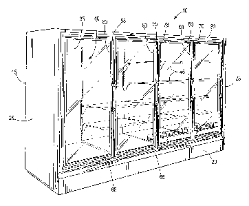
refrigeration circuit have no more than 150 grams of hydrocarbon refrigerant
to minimize the
likelihood that leaked refrigerant will ignite and cause adverse conditions in
the area
surrounding the merchandiser. To meet this requirement, existing systems using
hydrocarbon
refrigerant have several (i.e. two or more) hydrocarbon refrigerant loops,
each with no more
than 150 grams refrigerant charge, that are arranged in parallel with each
other to
cooperatively condition the area needing to be cooled.
SUMMARY
[0003a] According to an aspect of the present invention, there is
provided a
refrigeration system comprising: a first circuit including a first heat
exchanger, a second heat
exchanger, and a pump fluidly connected in series with the first heat
exchanger and the
second heat exchanger to circulate a coolant within the first circuit, wherein
the first heat
exchanger discharges heat from the coolant directly to an ambient environment;
and a second
circuit circulating a hydrocarbon refrigerant in heat exchange relationship
with the coolant in
the first circuit within the second heat exchanger to cool the hydrocarbon
refrigerant, the
second circuit including a compressor, the second heat exchanger, and a
refrigerated
merchandiser defining a product support area and having an evaporator fluidly
connected in
series with the compressor and the second heat exchanger, the evaporator
positioned to
condition the entire product support area within a predetermined temperature
threshold at or
- 1 -
CA 2942346 2017-12-27
81798807
below approximately 41 degrees Fahrenheit, wherein the first heat exchanger
includes a
condenser.
[0003b] According to another aspect of the present invention, there is
provided a
refrigeration system comprising: a first circuit including a first heat
exchanger, a second heat
exchanger, and a pump fluidly connected to the first heat exchanger and the
second heat
exchanger to circulate a first coolant within the first circuit; a second
circuit circulating a
fluid, the second circuit including a refrigerated merchandiser defining a
product support area
and having an evaporator in communication with the product support area to
condition the
area within a predetermined temperature range; a third circuit including the
second heat
exchanger, a chiller unit, and a compressor fluidly connected to the second
heat exchanger
and the chiller unit to circulate a hydrocarbon refrigerant in heat exchange
relationship with
the first coolant such that heat from the hydrocarbon refrigerant is absorbed
by the first
coolant within the second heat exchanger, the chiller unit positioned in
communication with
the second circuit such that heat from the fluid is transferred to the
hydrocarbon refrigerant in
the chiller unit; and a fourth circuit in heat exchange relationship with each
of the second
circuit and the third circuit, wherein the second circuit includes a condenser
and the fourth
circuit includes the chiller unit and a pump circulating a second fluid
through the condenser in
direct heat exchange relationship with the fluid of the second circuit to
extract heat from the
fluid, and wherein the second fluid is further in direct heat exchange
relationship with the
hydrocarbon refrigerant within the chiller unit to discharge heat to the third
circuit, wherein
the third circuit has a refrigerant charge not exceeding approximately 150
grams of
refrigerant.
[0003c] According to another aspect of the present invention, there is
provided a
refrigeration system comprising: a first circuit including a first
refrigerated merchandiser
defining a product support area and having an evaporator to maintain the
product support area
within a predetermined temperature range, the first circuit further including
a chiller unit and a
pump fluidly connected to the evaporator and the chiller unit to circulate a
coolant within the
first circuit; a second circuit including a condenser, the chiller unit, and a
compressor
circulating a hydrocarbon refrigerant through the second circuit and in heat
exchange
- 2 -
CA 2942346 2017-12-27
CA 02942346 2016-09-09
67363-1844
relationship with the coolant within the chiller unit to extract heat from the
coolant; and a
third circuit circulating a hydrocarbon refrigerant, the third circuit
including a second
refrigerated merchandiser defining a second product support area and having a
second
evaporator in communication with the second product support area to condition
the area
within a second predetermined temperature range, wherein the hydrocarbon
refrigerant within
the condenser is in heat exchange relationship with a fluid to discharge heat
from the
hydrocarbon refrigerant to the fluid, wherein the first circuit is in heat
exchange relationship
with the third circuit to extract heat from the hydrocarbon refrigerant of the
third circuit,
wherein the hydrocarbon refrigerant of the second circuit is in heat exchange
relationship with
the coolant of the first circuit to extract heat from the hydrocarbon
refrigerant of the third
circuit, and wherein a refrigerant charge of the second circuit does not
exceed approximately
150 grams of hydrocarbon refrigerant.
[0004] Some embodiments provide a modular, ultra-low charge
refrigeration system
that uses a hydrocarbon refrigerant (e.g., propane).
[0005] In one construction, an embodiment provides a refrigeration system
including a
first circuit with a first heat exchanger, a second heat exchanger, and a pump
fluidly
connected in series with the first heat exchanger and the second heat
exchanger to circulate a
coolant within the first circuit. The refrigeration system also includes a
second circuit that
circulates a hydrocarbon refrigerant in heat exchange relationship with the
coolant in the first
circuit within the second heat exchanger to cool the refrigerant. The second
circuit includes a
compressor, the second heat exchanger, and a refrigerated merchandiser, which
defines a
product support area. An evaporator is fluidly connected in series with the
compressor and the
second heat exchanger and positioned to condition the entire product support
area within a
predetermined temperature threshold at or below approximately 41 degrees
Fahrenheit.
[0006] In another construction, an embodiment provides a refrigeration
system
including a first circuit that has a first heat exchanger, a second heat
exchanger, and a pump
fluidly connected to the first heat exchanger and the second heat exchanger to
circulate a first
coolant within the first circuit. The refrigeration system also includes a
second circuit that
- 2a -
CA 02942346 2016-09-09
67363-1844
circulates a fluid and a refrigerated merchandiser defining a product support
area. An
evaporator is in communication with the product support area to condition the
area within a
predetermined temperature range. The refrigeration system also includes a
third circuit
including the second heat exchanger, a chiller unit, and a compressor fluidly
connected to the
second heat exchanger and the chiller unit to circulate a hydrocarbon
refrigerant in heat
exchange relationship with the first coolant. Heat from the hydrocarbon
refrigerant is
absorbed by the first coolant within the second heat exchanger. The chiller
unit is positioned
in communication with the second circuit such that heat from the fluid is
transferred to the
hydrocarbon refrigerant in the chiller unit. The third circuit defines a micro-
chiller refrigerant
loop having a refrigerant charge not exceeding approximately 150 grams of
refrigerant.
100071 In another construction, an embodiment provides a first circuit
including a
refrigerated merchandiser defining a product support area and having an
evaporator to
maintain the product support area within a predetermined temperature range.
The first circuit
further includes a chiller unit and a pump fluidly connected to the evaporator
and the chiller
unit to circulate a coolant within the first circuit. The refrigeration unit
also includes a second
circuit including a condenser, the chiller unit, and a compressor circulating
a hydrocarbon
refrigerant through the second circuit and in heat exchange relationship with
the coolant
within the chiller unit to extract heat from the coolant. Hydrocarbon
refrigerant within the
condenser is in heat exchange relationship with a fluid to discharge heat from
the hydrocarbon
refrigerant to the fluid, and the refrigerant charge of the second circuit
does not exceed
approximately 150 grams of hydrocarbon refrigerant.
100081 Other embodiments of the invention will become apparent by
consideration of
the detailed description and accompanying drawings.
BRIEF DESCRIPTION OF THE DRAWINGS
100091 FIG. 1 is a perspective view of an exemplary refrigerated
merchandiser
embodying the invention.
- 2b -
CA 02942346 2016-09-09
WO 2015/138051
PCT/US2015/013001
[0010] FIG. 2 is a
perspective view of another exemplary refrigerated merchandiser
embodying the invention
[0011] FIG. 3 is a
schematic view of a refrigeration system including several refrigeration
circuits for conditioning the product support areas of several merchandisers.
[0012] FIG. 4 is a
schematic view of one refrigeration circuit of the refrigeration system
of FIG. 2 including a high side cooling loop and a low side refrigerant loop.
[0013] FIG. 5 is a
schematic view of another refrigeration circuit of the refrigeration
system of FIG. 2 including a high side cooling loop, a low side refrigerant
loop, and an
intermediate refrigerant loop in heat exchange relationship with the high side
and low side
loops.
[0014] FIG. 6 is a
schematic view of another refrigeration circuit of the refrigeration
system of FIG. 2 including a high side cooling loop, a low side refrigerant
loop, and an
intermediate refrigerant loop in heat exchange relationship with the high side
and low side
loops.
[0015] Before any
embodiments of the invention are explained in detail, it is to be
understood that the invention is not limited in its application to the details
of construction and
the arrangement of components set forth in the following description or
illustrated in the
following drawings. The invention is capable of other embodiments and of being
practiced or
of being carried out in various ways.
DETAILED DESCRIPTION
[0016] FIG. 1
illustrates an exemplary refrigerated merchandiser 10 that may be located
in a supermarket or a convenience store or other retail setting (not shown).
The refrigerated
merchandiser 10 includes a case 15 that has a base 20, side walls 25, a case
top or canopy 30,
and a rear wall 35. The area or volume partially enclosed by the base 20, the
side walls 25,
the canopy 30, and the rear wall 35 defines an interior space or product
support area 40 that
supports food product in the case 15 (e.g., on shelves 45). The product
support area 40 is
cooled by a refrigeration system 100, which will be described in greater
detail below.
[0017] The case 15
also includes a casing or frame 50 located adjacent a front of the
merchandiser 10 to support doors 55. In particular, the frame 50 includes
vertical mullions 70
-3-
CA 02942346 2016-09-09
WO 2015/138051
PCT/US2015/013001
that define customer access openings 65 and that support the doors 55 over the
openings 65.
The openings 65 provide access to food product stored in the product support
area 40. The
mullions 70 are structural members spaced horizontally along the case 15.
[0018] Further with
respect to FIG. 1, the base 20 is disposed substantially below the
product support area 40 and can be supported by a floor or support surface
(not shown) of the
supermarket. The base 20 defines a lower portion of the product support area
40 that can
support a portion of the food product in the case 15. The base 20 includes an
air inlet located
adjacent a lower portion of the customer access openings 65 and in fluid
communication with
the product support area 40. The canopy 30 is disposed substantially above the
product
support area 40 and defines an upper portion of the product support area 40
that has an air
outlet.
[0019] FIG. 2
illustrates another exemplary refrigerated merchandiser 10' that may be
located in a supermarket or a convenience store or other retail setting (not
shown). Similar to
the merchandiser 10 discussed above with respect to FIG. 1, the merchandiser
10' includes a
case 15' that has abase 20', side walls 25', a case top or canopy 30', and a
rear wall 35'. The
area partially enclosed by the base 20', the side walls 25', the canopy 30',
and the rear wall
35' defines an interior space or product support area 40' that supports food
product in the
case 15' (e.g., on shelves 45'). The base 20' defines an interior bottom wall
75 and the
canopy 30' defining a first interior top wall 80. The area bounded by the
interior bottom wall
75, the first interior rear wall 35', and the first interior top wall 80
defines a product support
area 40'. An open front face allows customers access to the food product
stored in the case
15' without opening doors. The food product is stored on one or more shelves
45' in the
product support area 40'. The illustrated construction shows an upright
merchandiser 10',
although the merchandiser 10' can be a horizontal merchandiser (e.g., "coffin"-
style) or
another style of merchandiser.
[0020] In general,
the merchandisers 10, 10' can be a low temperature or a medium
temperature merchandiser depending on the product supported in the product
support areas
40, 40'. Low temperature merchandisers maintain the product support area 40,
40' at a
temperature of less than approximately 32 F. Medium temperature merchandisers
are
configured to maintain the product support area 40, 40' within a temperature
range of
approximately 32 F to approximately 41 F. Alternatively, the merchandisers 10,
10' may be
-4-
CA 02942346 2016-09-09
WO 2015/138051
PCT/US2015/013001
configured to maintain the product support area 40, 40' at other temperatures
(i.e., above
41 F).
[0021] FIG. 3
illustrates an exemplary multi-circuit refrigeration system 100 that is used
to condition the product support areas 40, 40'. Although not shown, the
refrigeration system
100 can be used in any commercial setting (e.g., a retail store, supermarket,
or an industrial
setting) or other settings that have temperature-controlled environments
(e.g., the
merchandisers 10, 10' described with regard to FIGS. 1 and 2).
[0022] With
reference to FIG. 3, the refrigeration system 100 includes a primary or first
circuit 105 (referred to as the "first circuit 105" for purposes of
description only) that
circulates a first cooling fluid, one or more second circuits 110 (one shown)
that circulate a
second cooling fluid, one or more third or micro-chiller circuits 115 (two
shown) that
circulate a third cooling fluid, one or more fourth circuits 117 (one shown)
that circulate a
fourth cooling fluid, one or more fifth circuits 118 (one shown) that
circulate a fifth cooling
fluid. The first cooling fluid is described in detail as a first coolant
including ambient water,
although it should be understood that another cooling fluid can be used (e.g.,
glycol, or a
water-glycol mixture). Also, while the second, third and fifth cooling fluids
are described in
detail as being the same cooling fluid, different fluids can be used among the
circuits.
[0023] FIGS. 3 and
4 show the first circuit 105 that includes a first heat exchanger 120
disposed in a housing 122, a second heat exchanger 125, and a pump 130 that
circulates the
first coolant serially through the components of the first circuit 105. The
first circuit 105 is in
heat exchange relationship with the second circuit 110 via the second heat
exchanger 125.
[0024] As
illustrated, the first heat exchanger 120 is an evaporative fluid cooler
(e.g.,
located on a rooftop of the commercial setting to discharge heat from the
coolant in the first
circuit 105 to the surrounding environment), although other types of heat
exchangers may be
used. A fan 132 is positioned to direct outside air across the heat exchanger
120. The first
heat exchanger 120 is in fluid communication with the second heat exchanger
125 via an inlet
line 135 and an outlet line 140. The illustrated first heat exchanger 120 also
includes a spray
circuit 145 with a secondary pump 150 that circulates water accumulated in the
bottom of the
housing 122 through spray outlets 152 positioned at the top of the housing 122
above the heat
exchanger 120.
-5-
CA 02942346 2016-09-09
WO 2015/138051
PCT/US2015/013001
[0025] Referring to
Figs. 3 and 5, the first circuit 105 also includes a sub-circuit 155 that
is fluidly coupled between the inlet line 135 and the outlet line 140. The sub-
circuit 155 is in
heat exchange relationship with the micro-chiller circuits 115 via third heat
exchangers 160.
A valve (not shown) can be coupled to the inlet line 135 and/or the outlet
line 140 to control
flow of the first cooling fluid to and/or from the second heat exchanger 125,
as well as
relative to the sub-circuits 155. Additional components (expansion valve,
receivers,
accumulators, etc.) can also be provided in the first circuit 105.
[0026] Referring
back to Figs. 3 and 4, each second circuit 110 circulates the second
cooling fluid or refrigerant (described as the "first refrigerant" for
purposes of description) to
condition the product support area 40, 40' of one or more merchandisers 10,
10'. The first
refrigerant is a hydrocarbon refrigerant such as propane. Part or all of the
second circuit 110
can be located remote from the first circuit 105.
[0027] With
reference to FIGS. 1-4 and 5, each second circuit 110 includes the secondary
heat exchanger 125, an evaporator 165, a compressor 170 (e.g., one compressor
170 or
several compressors 170 in an assembly), and an expansion valve 175 disposed
upstream of
the evaporator 165. The evaporator 165 is in communication with the product
support area
40, 40' to condition the area 40, 40' within a predetermined temperature
threshold based on
the type of product to be cooled. The evaporator 165 (e.g., microchannel or
round tube plate-
fin) is fluidly coupled with and returns heated first refrigerant to the
compressor 170 via a
suction line 180. The evaporator 165 also is fluidly coupled with the
secondary heat
exchanger 125 via an inlet line 182 to receive cooled, condensed hydrocarbon
refrigerant
from the secondary heat exchanger 125. The second circuit 110 also can include
other
components (valves, receivers, accumulators, etc.). The charge of hydrocarbon
refrigerant in
each second circuit 110 does not exceed, for example, approximately 150 grams
of
hydrocarbon refrigerant (e.g., the refrigerant charge is at or below 150
grams), although in
some constructions, the refrigerant charge may exceed 150 grams (e.g., based
on the
maximum charge established by government or safety regulations).
[0028] Figs. 3, 5,
and 6 illustrate the micro-chiller circuits 115 that circulate a
hydrocarbon refrigerant (e.g., propane) as the third cooling fluid (referred
to as the "second
refrigerant" for purposes of description). Each micro-chiller circuit 115
includes the third
heat exchanger 160, a chiller unit 185, and a compressor 190 (e.g., one
compressor 190 or
several compressors 190) fluidly connected to the heat exchanger 160 and the
chiller unit 185
-6-
CA 02942346 2016-09-09
WO 2015/138051
PCT/US2015/013001
to circulate the second refrigerant through the circuit 115. The micro-chiller
circuit 115 also
can include other components (valves, receivers, accumulators, etc.). As
shown, the
compressors 190 cycle on/off based on the temperature of the fourth cooling
fluid exiting the
chiller units 185 within the fourth circuit 117.
[0029] The chiller
unit 185 is fluidly coupled with the compressor 190 via a suction line
200 to deliver heated hydrocarbon refrigerant from the chiller unit 185 to the
compressor 190.
The chiller unit 185 also is fluidly coupled with the third heat exchanger 160
via an inlet line
205 to receive cooled, condensed hydrocarbon refrigerant. As shown, an
expansion valve 210
can be located in the inlet line 205 to create a pressure differential to
control the pressure of
the fluid delivered to the chiller unit 185. The refrigerant charge of the
micro-chiller circuit
115 does not exceed, for example, approximately 150 grams of hydrocarbon
refrigerant.
[0030] Referring
back to Figs. 3, 5, and 6, the fourth circuit 117 circulates a non-
hydrocarbon fluid as the fourth cooling fluid to condition the product support
area 40, 40' of
one or more merchandisers 10, 10' within the circuit 117. In the illustrated
circuit 117, the
fourth cooling fluid is a water or water-glycol mixture (referred to as the
"second coolant" for
purposes of description). The fourth circuit 117 includes the chiller units
185, a fourth heat
exchanger 215, an evaporator 220, a pump 225, a multi-port valve 230, and a
valve 235
positioned upstream of the evaporator 220. The evaporator 220 is disposed in
the
merchandiser 10, 10' to condition the product display area 40, 40'. As shown,
the fourth heat
exchanger 215 and the evaporator 220 are fluidly coupled in parallel to the
pump 225 such
that the fourth cooling fluid is divided between the heat exchanger 215 and
the evaporator
220 (e.g., by a valve, not shown). The fourth circuit 117 also can include
other components
(valves, receivers, accumulators, etc.). As illustrated, the fourth circuit
117 conditions
product at temperatures above approximately 40 F (i.e. product that can be
cooled directly
with chilled coolant).
[0031[1 The fifth
circuit 118 circulates a hydrocarbon refrigerant as the fifth cooling fluid
(referred to as the "third refrigerant" for purposes of description) and is in
heat exchange
relationship with the fourth circuit 117 via the fourth heat exchanger 215.
With the exception
of the heat exchanger 215 in place of the heat exchanger 125, the components
of the fifth
circuit are the same as the second circuit 110. In particular, the fifth
circuit 118 includes the
fourth heat exchanger 215, the evaporator 165, the compressor 170 (e.g., one
compressor 170
or several compressors 170), and the expansion valve 175 disposed upstream of
the
-7-
CA 02942346 2016-09-09
67363-1844
evaporator 165. The evaporator 165 is in communication with the product
support area 40, 40' to
condition the area 40, 40- within a predetermined temperature threshold based
on the type of
product to be cooled. The evaporator 165 (e.g., microchannel or round tube
plate-fin) is fluidly
coupled with and returns heated hydrocarbon refrigerant to the compressor 170
via a suction line
.. 180. The evaporator 165 also is fluidly coupled with the fourth heat
exchanger 215 via an inlet
line 182 to receive cooled, condensed hydrocarbon refrigerant from the fourth
heat exchanger 215.
The fifth circuit 118 also can include other components (valves. receivers,
accumulators, etc.).
The charge of hydrocarbon refrigerant in each second circuit 110 does not
exceed approximately
150 grams of hydrocarbon refrigerant (e.g., the refrigerant charge is at or
below 150 grams).
100321 FIG. 3 illustrates that the refrigeration system 100 can be
implemented with all of
the circuits 105, 110, 115, 117, 118, and FIGS. 4-6 illustrate that the
refrigeration system 100 can
be implemented with different combinations of the circuits 105, 110, 115, 117,
118. With
reference to FIG. 3, the refrigeration system is illustrated as being
implemented with all of the
circuits 105, 110, 115, 117, 118. In operation, beginning with the fourth
circuit 117, the second
coolant is circulated by the pump 225 to the multi-port valve 230, which
directs the second
coolant directly to the chiller units 185 when the temperature of the first
coolant is below
approximately 38EF. When the temperature of the first coolant is above this
threshold
temperature, the multi-port valve 230 directs the second coolant through an
auxiliary loop 240 that
is connected to the valve 230 and to the fourth circuit at a point upstream of
the chiller units 185.
Second coolant that is circulated through the auxiliary loop 240 is at least
partially cooled by heat
exchange with the first coolant circulating through the first circuit 105
downstream of the first
heat exchanger 120. The cooled second coolant is then directed through the
chiller units 185 and,
depending on the temperature of the second coolant exiting the chiller units
185, is further cooled
by heat exchange with the second refrigerant circulating through the micro-
chiller circuits 115.
100331 With continued reference to FIG. 3, second coolant exiting the
chiller units 185 is
delivered to the fourth heat exchanger 215 and to the evaporator 220 in
parallel (e.g., via a valve,
not shown). Second coolant flowing through the evaporator 220 is in heat
exchange relationship
with air flowing through the evaporator 220 so that the product support area
40, 40' can be
conditioned based on predefined parameters. Heated second coolant exiting the
evaporator 220 is
returned to the pump 225.
- 8 -
CA 02942346 2016-09-09
WO 2015/138051
PCT/US2015/013001
[0034] The fourth
heat exchanger 215 functions as a condenser for the fifth circuit 118 to
reject heat from the hydrocarbon refrigerant in the circuit 110 to the second
coolant in the
fourth circuit 117. The condensed hydrocarbon refrigerant in the fifth circuit
118 is directed
from the heat exchanger 215 through the inlet line 182 to the evaporator 165
through the
expansion valve 175. The evaporator 165 is in a heat exchange relationship
with air passing
through the evaporator 165 to condition the product support area 40' 40'.
Heated
hydrocarbon refrigerant is then directed to the compressor 170 through the
suction line 180
and compressed before returning to the heat exchanger 125.
[0035] After heat
is transferred from the hydrocarbon refrigerant to the second coolant
within the heat exchanger 215, the second coolant returns to the pump 225. As
illustrated,
second coolant exiting the heat exchanger 215 combines with second coolant
exiting the
evaporator 220 upstream of the pump 225.
[0036] FIG. 3
further illustrates that the second coolant in the fourth circuit 117 is in
heat
exchange relationship with the second refrigerant in each micro-chiller
circuit 115 to reject
heat from the second coolant to the second refrigerant. Heated second
refrigerant in each of
the circuits 115 is drawn into the compressor 190 via the suction line 200 and
then
compressed before circulating through the third heat exchanger 160 where heat
is rejected
from the refrigerant to the first coolant in the first circuit 105.
[0037] In
operation, the third heat exchanger 160 functions as a condenser for the micro-
chiller circuit 115 to reject heat from the hydrocarbon refrigerant in the
circuit 115 to the
cooling fluid in the first circuit 105. After heat is transferred from the
hydrocarbon refrigerant
to the first coolant within the heat exchanger 160, the heated first coolant
is directed through
the sub-circuit 155 to the outlet line 140 upstream of the pump 130.
[0038] The second
heat exchanger 125 functions as a condenser for the second circuit
110 to reject heat from the hydrocarbon refrigerant in the circuit 110 to the
first coolant
circulating within the first circuit 105. Condensed hydrocarbon refrigerant in
the second
circuit 110 is then directed through the inlet line 182 to the evaporator 165
through the
expansion valve 175. The evaporator 165 is in a heat exchange relationship
with air that is
directed to the product support area 40, 40' to condition the area 40' 40'.
The heated
refrigerant is then directed to the compressor 170 through the suction line
180 and
compressed before returning to the heat exchanger 125.
-9-
CA 02942346 2016-09-09
WO 2015/138051
PCT/US2015/013001
[0039] After heat
is transferred from the hydrocarbon refrigerant to the first coolant
within the heat exchanger 125, the heated first coolant is directed to the
first heat exchanger
120 by the pump 130. As illustrated, heated first coolant returning from the
second heat
exchanger 125 is combined with heated first coolant returning from the heat
exchangers 160
of the sub-circuits 155 upstream of the pump 130. The combined, heated first
coolant is then
pumped to the first heat exchanger 120. Heat from the first coolant flowing
through the heat
exchanger 120 is transferred to fluid sprayed onto the heat exchanger 120 by
the spray outlets
152 via evaporative cooling. The fan 132 increases the evaporative cooling
effect. The cooled
first coolant is returned to the heat exchanger 125 and to the sub-circuits
155 (e.g., via a
valve, not shown), and fluid accumulated at the bottom of the housing 122
returns to the
spray outlets 152 via the pump 150.
[0040] FIG. 4
illustrates an exemplary implementation of the refrigeration system 100
that includes a portion of the first circuit 105, without the sub-circuit 155,
in heat exchange
relationship with the second circuit 110. The first and second circuits 105,
110 operate as
described with regard to FIG. 3 to condition the product support area 40, 40'.
As illustrated,
the closed loop circuit 110 minimizes the amount of refrigerant charge needed
to condition
the area 40, 40' while still maximizing the efficiencies of hydrocarbon
refrigerant.
Furthermore, by providing discrete circuits 105, 110, the circuits 105, 110
can be
implemented with or without additional circuits.
[0041] FIG. 5
illustrates another exemplary implementation of the refrigeration system
100 that includes a portion of the first circuit 105, the micro-chiller
circuits 115, a portion of
the fourth circuit 117, and the fifth circuit 118. As shown, the first circuit
105 is provided
with the sub-circuits 155 and without connection to the second heat exchanger
125, and the
fourth circuit 117 is provided with a closed loop between the micro-chiller
circuits 115 and
the fifth circuit 118 without connection to the evaporator 220. As described
with regard to
FIG. 3, the third hydrocarbon refrigerant within the fifth circuit 118 is in
heat exchange
relationship with the second coolant in the fourth circuit 117 to reject heat
to the second
coolant. In turn, the second coolant is in heat exchange relationship with the
second
refrigerant within the chiller units 185 to reject heat to the second
refrigerant. Heat from the
second refrigerant in the circuit 115 is then rejected to the first coolant
within the third heat
exchangers 160, and heat from the first coolant is rejected to the surrounding
environment
within the first heat exchanger 120.
-10-
CA 02942346 2016-09-09
WO 2015/138051
PCT/US2015/013001
[0042] FIG. 6
illustrates another exemplary implementation of the refrigeration system
100 that includes a portion of the first circuit 105, the micro-chiller
circuits 115, and a portion
of the fourth circuit 117. As shown, the first circuit 105 is provided with
the sub-circuits 155
and without connection to the second heat exchanger 125, and the fourth
circuit 117 is
provided with a closed loop between the micro-chiller circuits 115 and the
evaporator 220
without connection to the fifth circuit 118. As described with regard to FIG.
3, the second
coolant is in heat exchange relationship with air that conditions the area 40,
40', and heated
second coolant in the fourth circuit 117 is rejected to the second refrigerant
within the chiller
units 185. Heat from the second refrigerant is then rejected to the first
coolant within the heat
exchangers 160, and heat from the first coolant is rejected to the surrounding
environment
within the heat exchanger 120.
[0043] By providing
discrete, closed loop merchandiser hydrocarbon refrigerant circuits
(e.g., circuits 110, 118) and micro-chiller circuits 115 that circulate
hydrocarbon refrigerant,
the amount of refrigerant charge in each circuit can be kept small while still
maximizing the
efficiencies of hydrocarbon refrigerant. Further, hydrocarbon refrigerant such
as propane is
implemented in different parts of the refrigeration system 100, not just in an
intermediate
circuit (e.g., in the micro-chiller circuits 115) or in a low side circuit
(like the second or fifth
circuits 110, 118). In other words, propane or another hydrocarbon refrigerant
can be
implemented in several discrete refrigerant loops to increase the efficiency
of the overall
system 100 and mitigating the potential for flammability risk.
[0044] Various
features and advantages of the invention are set forth in the following
claims.
-11-