Note: Descriptions are shown in the official language in which they were submitted.
CA 02942417 2016-11-15
WO 2015/135056
PCT/CA2014/050873
SYSTEM AND METHOD FOR HEALTH IMAGING INFORMATICS
FIELD
The present disclosure relates to imaging methods for use in
minimally invasive therapy, image guided medical procedures using multi-
modal imaging modalities, and methods and systems for providing
treatment planning information.
BACKGROUND
The term "informatics" has been used in various different contexts
in medicine. In radiology, "informatics" may be used to refer to
management of digital images, typically in the form of a picture archiving
and communication system (PACS), and so the term "imaging informatics"
may be more accurate. Systems for this type of management include
Philips's IntelliSenseTM PACS, Siemens's SyngoTM framework, and GE's
CentricityTM PACS and Imaging Analytics products, among others, and the
focus of these systems is generally limited to the storage, organization,
and access of DICOM images.
In a surgical context, on the other hand, "informatics" has been
used to refer to a broad and diverse range of operating room aspects. GE
offers perioperative software that helps manage operating room (OR)
1
CA 02942417 2016-09-12
WO 2015/135056
PCT/CA2014/050873
scheduling, anesthesia documentation, surgical supplies, and throughput.
NDS offers a series of products (e.g., ConductORTM, ScaIeORTM, and
ZeroWireTM) focused on OR video streaming and distribution. Karl Storz's
OR1 informatics platform is also centered on OR endoscopic video. Stryker
offers iSuiteTM, which manages video, surgical lights, booms, and surgical
navigation devices.
Other, more specialized, informatics systems exist in the
cardiovascular space, consolidating various cardiac images (e.g.,
echocardiograms, X-rays, magnetic resonance (MR) images, etc.) along
with electrocardiogram (ECG) and electrophysiology results. The intent is
to consolidate the plethora of data that comes from a variety of sources
into a central place so that it is readily available to the clinician (e.g.,
the
cardiologist, the cardiac surgeon, or another care provider) in its entirety,
facilitating more informed decisions regarding a patient's care. Philips
XceleraTM and GE's CentricityTM Cardio are two commercially-available
cardiovascular informatics systems.
As for other specialized surgical informatics platforms, Voyent
Healthcare developed an orthopedic informatics solution over the mid to
late 2000s. It features integrated orthopedic implant planning, web-based
viewing, card swipe access, and operating room scheduling.
Contrary to the cardiovascular and orthopedic spaces, the
specialized neurological/neurosurgical informatics landscape is sparse and
underserved, despite the need and high demand among neurosurgeons
for real-time information that can inform them on important clinical
decisions before, during, and after surgery. This could be attributed to
several key differences between the surgical disciplines, most notably the
2
CA 02942417 2016-09-12
WO 2015/135056
PCT/CA2014/050873
comparatively fewer imaging studies performed in neurosurgical
procedures, which, in most cases, is limited to pre-operative MR or CT.
However, with the growing demand and adoption of minimally invasive
neurological procedures that require new sophisticated imaging tools for
accurate guidance, this trend is quickly changing.
Thus there is a need for integrating multi-modality imaging
solutions that will take visualization, planning, and navigation, in pre-
operative, intra-operative, and post-operative contexts to the next level to
provide better care for patients.
SUMMARY
In various examples, the present disclosure provides systems and
methods supporting the implementation of imaging and surgical
informatics in neurology and neurosurgery.
In some examples, the present disclosure provides a computer
implemented method for providing planning information for a neurology
procedure, the method may include: receiving a first set of data
characterizing the neurology procedure; accessing one or more historical
databases containing historical data about historical procedures;
determining one or more historical data relevant to the neurology
procedure, based on a determination of similarity to the first set of data;
determining, from the one or more historical data, one or more historical
instances of one or more procedure parameters relevant to the neurology
procedure; and displaying, on an output device, the one or more historical
instances of the one or more procedure parameters.
In some examples, the present disclosure provides a computer
implemented method for providing feedback for a neurology procedure,
3
CA 02942417 2016-09-12
WO 2015/135056
PCT/CA2014/050873
the method may include: accessing a remote database containing pre-
procedure and post-procedure image data; determining, using
identification information, a set of pre-procedure image data and a set of
post-procedure image data associated with a given neurology procedure
for a patient; performing a quantitative comparison of the pre-procedure
image data and the post-procedure image data; and displaying, on an
output device, the quantitative comparison.
In some examples, the present disclosure provides a system for
providing information about a neurology procedure, the system may
include: a central system, comprising one or more processors, in
communication with two or more databases, each of the two or more
databases storing different information associated with the neurology
procedure; one or more data processing modules executable by the
central system, the one or more data processing modules including at
least one planning module that, when executed, causes the system to:
receive a first set of data characterizing the neurology procedure; access
one or more historical databases containing historical data about historical
procedures; determine one or more historical data relevant to the
neurology procedure, based on a determination of similarity to the first
set of data; determine, from the one or more historical data, one or more
historical instances of one or more procedure parameters relevant to the
neurology procedure; and cause an output device to display the one or
more historical instances of the one or more procedure parameters.
In some examples, the present disclosure provides a system for
providing feedback about a neurology procedure, the system may include:
a central system, comprising one or more processors, in communication
4
CA 02942417 2016-09-12
WO 2015/135056
PCT/CA2014/050873
with one or more remote databases containing pre-procedure and post-
procedure image data; and one or more data processing modules
executable by the central system, the one or more data processing
modules including at least one feedback module that, when executed,
causes the system to: access at least one remote database containing the
pre-procedure and post-procedure image data; determine, using
identification information, a set of pre-procedure image data and a set of
post-procedure image data associated with a given neurology procedure
for a patient; perform a quantitative comparison of the pre-procedure
image data and the post-procedure image data; and cause an output
device to display the quantitative comparison.
BRIEF DESCRIPTION OF THE DRAWINGS
Embodiments will now be described, by way of example only, with
reference to the drawings, in which:
FIG. 1 illustrates the insertion of an access port into a human brain,
for providing access to internal brain tissue during a medical procedure;
FIG. 2 shows an exemplary navigation system to support minimally
invasive access port-based surgery;
FIG. 3 is a block diagram illustrating a control and processing
system that may be used in the navigation system shown in Fig. 2;
FIGS. 4A is a flow chart illustrating a method involved in a surgical
procedure using the navigation system of Fig. 2;
FIGS. 4B is a flow chart illustrating a method of registering a
patient for a surgical procedure as outlined in Fig. 4A;
5
CA 02942417 2016-09-12
WO 2015/135056
PCT/CA2014/050873
FIGS. 5A and 56 illustrate selectable displays, in a user interface,
showing tissue analysis information provided by an example of the
disclosed informatics system;
FIG. 5C is a diagram showing an example system involving four
aspects of patient care;
FIG. 6 is a flow chart demonstrating an example method of
identifying similar prior tissue analyses by performing a similarity analysis
between local diagnostic data and archival local tissue diagnostic data
stored in a tissue analysis database;
FIG. 7 is a diagram showing how an example of the disclosed
informatics system communicates with various other information sources;
FIGS. 8 and 9 are diagrams showing examples of plug-ins useable
by an example of the disclosed informatics system;
FIG. 10A shows an example of a user interface provided by an
example of the disclosed informatics system, to provide information
during treatment planning;
FIG. 106 shows a flowchart showing an example method for
treatment planning, using an example of the disclosed informatics
system;
FIG. 11 illustrates an example of how pre- and post-op information
may be quantified and stored in an example of the disclosed informatics
system; and
FIG. 12 shows an example of a user interface provided by an
example of the disclosed informatics system, to provide intra-operative
information.
6
CA 02942417 2016-09-12
WO 2015/135056
PCT/CA2014/050873
DETAILED DESCRIPTION
Various embodiments and aspects of the disclosure will be
described with reference to details discussed below. The following
description and drawings are illustrative of the disclosure and are not to
be construed as limiting the disclosure. Numerous specific details are
described to provide a thorough understanding of various embodiments of
the present disclosure. However, in certain instances, well-known or
conventional details are not described in order to provide a concise
discussion of embodiments of the present disclosure.
As used herein, the terms, "comprises" and "comprising" are to be
construed as being inclusive and open ended, and not exclusive.
Specifically, when used in the specification and claims, the terms,
"comprises" and "comprising" and variations thereof mean the specified
features, steps or components are included. These terms are not to be
interpreted to exclude the presence of other features, steps or
components.
As used herein, the term "exemplary" means "serving as an
example, instance, or illustration," and should not be construed as
preferred or advantageous over other configurations disclosed herein.
As used herein, the terms "about" and "approximately" are meant
to cover variations that may exist in the upper and lower limits of the
ranges of values, such as variations in properties, parameters, and
dimensions. In one non-limiting example, the terms "about" and
"approximately" mean plus or minus 10 percent or less.
Unless defined otherwise, all technical and scientific terms used
herein are intended to have the same meaning as commonly understood
7
CA 02942417 2016-09-12
WO 2015/135056
PCT/CA2014/050873
by one of ordinary skill in the art. Unless otherwise indicated, such as
through context, as used herein, the following terms are intended to have
the following meanings.
As used herein, the phrase "access port" refers to a cannula,
conduit, sheath, port, tube, or other structure that is insertable into a
subject, in order to provide access to internal tissue, organs, or other
biological substances. In some embodiments, an access port may directly
expose internal tissue, for example, via an opening or aperture at a distal
end thereof, and/or via an opening or aperture at an intermediate location
along a length thereof. In other embodiments, an access port may provide
indirect access, via one or more surfaces that are transparent, or partially
transparent, to one or more forms of energy or radiation, such as, but not
limited to, electromagnetic waves and acoustic waves.
As used herein the phrase "intra-operative" refers to an action,
process, method, event or step that occurs or is carried out during at least
a portion of a medical procedure. Intra-operative, as defined herein, is not
limited to surgical procedures, and may refer to other types of medical
procedures, such as diagnostic and therapeutic procedures.
It is noted that the phrase "outcome", as used herein, refers to
quantifiable methods to measure mortality and morbidity of the subject.
This includes, but is not limited to, measurement of actual patient
function, including direct measures of tissue viability, or higher-level
function, as well as in-direct measurements, tests and observations. An
outcome may also refer to the economic outcome of a procedure (in a
specific or broad sense), and may include the time for the procedure, the
8
CA 02942417 2016-09-12
WO 2015/135056
PCT/CA2014/050873
equipment and personal utilization, drug and disposable utilization, length
of stay, and indications of complications and/or comorbidities.
Embodiments of the present disclosure provide imaging devices
that are insertable into a subject or patient for imaging internal tissues,
and methods of use thereof. Some embodiments of the present disclosure
relate to minimally invasive medical procedures that are performed via an
access port, whereby surgery, diagnostic imaging, therapy, or other
medical procedures (e.g. minimally invasive medical procedures) are
performed based on access to internal tissue through the access port.
In some examples, the present disclosure may provide an
alternative to or a complementary system to conventional tissue sampling
techniques. In many medical procedures, tissue samples are excised or
examined, for example, during the surgical removal of a tumor.
Conventionally, in the fields of medical imaging and surgical diagnostics,
taking a tissue sample and performing histopathology examination of it
using a microscope, often with staining of that tissue, remains the gold
standard for tissue diagnosis. This typically involves resection in a surgical
suite and transfer of the sample to a pathology laboratory. However, this
approach may be fraught with problems and issues. For example,
conventional methods of tissue analysis are typically unable to accurately
and painlessly access tissue, and may possibly seed tumor cells through
the biopsy process. It may also be impractical to perform multiple biopsies
to enable proper examination of heterogeneous tumors. Tissue samples
are also often mislabeled during the process, which can result due to
sample mix-up or labeling errors, resulting in faulty diagnosis.
Furthermore, pathology results may be discordant with the imaging
9
CA 02942417 2016-09-12
WO 2015/135056
PCT/CA2014/050873
results. Conventional workflow also often may have a poor feedback loop
to radiologists, which may hinder them from improving their diagnostic
accuracy for future cases. This also can result in an unnecessary delay
between biopsy and pathology results, resulting in a reduction in positive
patient outcomes.
In some examples, the present disclosure may enable the use of
imaging and image guidance, to replace or supplement tissue sampling,
for example as part of a multi-faceted treatment approach.
In some examples, the present disclosure may help to integrate
information from separate health systems and/or help to communicate
information across separate health systems, such as health-care
management systems from separate countries.
The health-care industries throughout the world typically consist of
various systems of health-care management and treatment, from private
health-care services to public, state-based and nationalized health-care
systems to a combination of these systems at regional levels.
Conventionally, it has been a challenge to integrate health systems from
different countries. The variety of service structures available to patients
across the United States (U.S.) and Canada, for example, leads to several
different methods of collection of health-related data, which may affect
the availability of such data to researchers and administrative officials.
For example, in the U.S., the combination of data-management
systems, laws around confidentiality and access with respect to patient-
related health data may lead to difficulty in using data collected from
patients to facilitate relevant and crucial research projects, and to develop
policies and procedures for effective and innovative population-based
CA 02942417 2016-09-12
WO 2015/135056
PCT/CA2014/050873
health issues.
In another example, Canada's public patient health-record
management systems are typically designed with two goals in mind: to
provide researchers with relevant patient data for medical research
purposes, and to aid administrators in the development of effective
population-based health policies. Both of these aims may facilitate the
progress of an integrated, interactive and intuitive health-care system
that is built on the efficient allocation of research and policy resources. A
public system of health-records collection and management may provide
advantages, such as an understanding of surgical waiting lists, the
utilization of resources by those with a specific health problem, and
understanding the relationship between drug utilization and patient use of
other health interventions.
Further, the data collected in public health care systems can be
used to develop health-care management policies for populations, trace
health-trends in populations and to address issues of ethics,
confidentiality and long-term health of individuals and populations. Using
the method of individual data sets to infer health trends for populations
may be an important factor in effective health resource management.
Jurisdictions with nationalized health-care systems typically have
methods in place to systematically collect and store patient information at
the national, regional and provincial levels. However, the lack of
aggregate data collection systems in the health-care field is problematic
for jurisdictions without public health care, such as the U.S. In the U.S.,
such a central data-collection and management system does not exist due
to the lack of a centralized health-care system, the existence of private
11
CA 02942417 2016-09-12
WO 2015/135056
PCT/CA2014/050873
health-care providers, state-level health-care management policies that
do not provide reciprocity in exchanging of patient information and health
records and the existence of privacy laws that prevent the collection of
health-related data for the purposes of the creation of population-based
healthcare policies or institutional-based healthcare policies. The present
disclosure may provide a way for centralizing and/or integrating such
disparate sources of information.
In Canada, the current linked health data collection, storage and
management systems divide patient information into six types of files
which are arranged according to the information collected on individual
patients through the health care system. These six types are: medical
services, hospital separations, drug prescriptions for the elderly, long term
care services, deaths and births. The current system is currently
undergoing linkage based on a methodology that focuses on developing
an aggregate system of data collection. One problem with this system is
the existence of "grey areas" in the links, which lead to the possibility of
false positives and bad links being developed, potentially misleading
research trends, obfuscating methodologies and creating skewed results.
Another problem with the current system is that it does not allow for data
exchange across different systems, as would be the case if the Canadian
health care data management systems were to be applied to the mix of
public-private systems in the U.S., in their current state.
In some examples, the present disclosure may enable better
sharing of information across separate data sources within a given health
system, as well as across separate health systems. Example embodiments
of the present disclosure will be described with reference to neurology and
12
CA 02942417 2016-09-12
WO 2015/135056
PCT/CA2014/050873
neurosurgery procedures, as illustrated by the figures described below.
FIG. 1 illustrates the insertion of an access port into a human brain,
for providing access to internal brain tissue during a medical procedure. In
FIG. 1, access port 12 is inserted into a human brain 10, providing access
to internal brain tissue. Access port 12 may include such instruments as
catheters, surgical probes, or cylindrical ports such as the NICO
BrainPathTM. Surgical tools and instruments may then be inserted within
the lumen of the access port 12 in order to perform surgical, diagnostic or
therapeutic procedures, such as resecting tumors as necessary. In some
examples, the present disclosure may apply equally well to catheters, DBS
needles, a biopsy procedure, and also to biopsies and/or catheters in
other medical procedures performed on other parts of the body.
In the example of a port-based surgery, a straight or linear access
port 12 is typically guided down a sulci path of the brain 10. Surgical
instruments would then be inserted down the access port 12.
Optical tracking systems, used in the medical procedure, may track
the position of a part of the instrument that is within line-of-site of the
optical tracking camera. These optical tracking systems also typically
require a reference to the patient to know where the instrument is relative
to the target (e.g., a tumor) of the medical procedure. These optical
tracking systems typically require a knowledge of the dimensions of the
instrument being tracked so that, for example, the optical tracking system
is able to determine the position in space of a tip of a medical instrument
relative to the tracking markers being tracked.
Referring to FIG. 2, an exemplary navigation system environment
200 is shown, which may be used to support navigated image-guided
13
CA 02942417 2016-09-12
WO 2015/135056
PCT/CA2014/050873
surgery. As shown in FIG. 2, surgeon 201 conducts a surgery on a patient
202 in an operating room (OR) environment. An example medical
navigation system 205 comprising an equipment tower, tracking system,
display(s) and tracked instrument(s) assist the surgeon 201 during his
procedure. An operator 203 may also be present to operate, control and
provide assistance for the medical navigation system 205.
Referring to FIG. 3, a block diagram is shown illustrating an
example control and processing system 300 that may be used in the
medical navigation system 205 shown in FIG. 2 (e.g., as part of the
equipment tower). As shown in FIG. 3, in one example, control and
processing system 300 may include one or more processors 302, an
internal and/or external memory 304, a system bus 306, one or more
input/output interfaces 308, a communications interface 310, and storage
device 312. Control and processing system 300 may be interfaced with
other external devices, such as tracking system 321, data storage 342,
and external user input and output devices 344, which may include, for
example, one or more of a display, keyboard, mouse, sensors attached to
medical equipment, foot pedal, and microphone and speaker. Data
storage 342 may be any suitable data storage device, such as a local or
remote computing device (e.g. a computer, hard drive, digital media
device, or server) having a database stored thereon. In the example
shown in FIG. 3, data storage device 342 includes identification data 350
for identifying one or more medical instruments 360 and configuration
data 352 that associates customized configuration parameters with one or
more medical instruments 360. Data storage device 342 may also include
preoperative image data 354 and/or medical procedure planning data 356.
14
CA 02942417 2016-09-12
WO 2015/135056
PCT/CA2014/050873
Although data storage device 342 is shown as a single device in FIG. 3, it
will be understood that in other embodiments, data storage device 342
may be provided as multiple storage devices.
Medical instruments 360 may be identifiable by control and
processing unit 300. Medical instruments 360 may be connected to and
controlled by control and processing unit 300, or medical instruments 360
may be operated or otherwise employed independent of control and
processing unit 300. Tracking system 321 may be employed to track one
or more of medical instruments 360 and spatially register the one or more
tracked medical instruments to an intra-operative reference frame. For
example, medical instruments 360 may include tracking markers such as
tracking spheres that may be recognizable by a tracking camera 307. In
one example, the tracking camera 307 may be an infrared (IR) tracking
camera. In another example, a sheath placed over a medical instrument
360 may be connected to and controlled by control and processing unit
300.
Control and processing unit 300 may also interface with a number
of configurable devices, and may intra-operatively reconfigure one or
more of such devices based on configuration parameters obtained from
configuration data 352. Examples of devices 320, as shown in FIG. 3,
include one or more external imaging devices 322, one or more
illumination devices 324, a robotic arm, the tracking camera 307, one or
more projection devices 328, and one or more displays 311.
Exemplary aspects of the disclosure can be implemented via
processor(s) 302 and/or memory 304. For example, the functionalities
described herein can be partially implemented via hardware logic in
CA 02942417 2016-09-12
WO 2015/135056
PCT/CA2014/050873
processor 302 and partially using the instructions stored in memory 304,
as one or more processing modules or engines 370. Example processing
modules include, but are not limited to, user interface engine 372,
tracking module 374, motor controller 376, image processing engine 378,
image registration engine 380, procedure planning engine 382, navigation
engine 384, and context analysis module 386. While the example
processing modules are shown separately in FIG. 3, in one example the
processing modules 370 may be stored in the memory 304 and the
processing modules may be collectively referred to as processing modules
370.
In some examples, the control and processing system 300 may
include one or more interfaces, such as communications interface 310, for
communicating with a central informatics system, as described further
below. One or more processing modules or engines 370, such as the
procedure planning engine 382 and the user interface engine 372, may
receive data communicated from the informatics system and may use
such data in its processing prior to, during, or after an operation, for
example. The control and processing system 300 may also communicate
data, such as image data from image processing engine 378, to the
informatics system.
It is to be understood that the control and processing system 300 is
not intended to be limited to the components shown in FIG. 3. For
example, one or more components of the control and processing system
300 may be provided as an external component or device. In one
example, navigation module 384 may be provided as an external
16
CA 02942417 2016-09-12
WO 2015/135056
PCT/CA2014/050873
navigation system that is integrated with control and processing system
300.
Some embodiments may be implemented using processor 302
without additional instructions stored in memory 304. Some embodiments
may be implemented using the instructions stored in memory 304 for
execution by one or more general purpose microprocessors. Thus, the
disclosure is not limited to a specific configuration of hardware and/or
software.
While some embodiments can be implemented in fully functioning
computers and computer systems, various embodiments are capable of
being distributed as a computing product in a variety of forms and are
capable of being applied regardless of the particular type of machine or
computer readable media used to actually effect the distribution.
At least some aspects disclosed can be embodied, at least in part,
in software. That is, the techniques may be carried out in a computer
system (such as the control and processing system 300 described above,
or other computer system) or other data processing system in response to
its processor, such as a microprocessor, executing sequences of
instructions contained in a memory, such as ROM, volatile RAM, non-
volatile memory, cache or a remote storage device.
A computer readable storage medium can be used to store software
and data which, when executed by a data processing system, causes the
system to perform various methods. The executable software and data
may be stored in various places including for example ROM, volatile RAM,
nonvolatile memory and/or cache. Portions of this software and/or data
may be stored in any one of these storage devices.
17
CA 02942417 2016-09-12
WO 2015/135056
PCT/CA2014/050873
Examples of computer-readable storage media include, but are not
limited to, recordable and non-recordable type media such as volatile and
non-volatile memory devices, read only memory (ROM), random access
memory (RAM), flash memory devices, floppy and other removable disks,
magnetic disk storage media, optical storage media (e.g., compact discs
(CDs), digital versatile disks (DVDs), etc.), among others. The instructions
may be embodied in digital and analog communication links for electrical,
optical, acoustical or other forms of propagated signals, such as carrier
waves, infrared signals, digital signals, and the like. The storage medium
may be the internet cloud, or a computer readable storage medium such
as a disc.
At least some of the methods described herein are capable of being
distributed in a computer program product comprising a computer
readable medium that bears computer usable instructions for execution by
one or more processors, to perform aspects of the methods described.
The medium may be provided in various forms such as, but not limited to,
one or more diskettes, compact disks, tapes, chips, USB keys, external
hard drives, wire-line transmissions, satellite transmissions, internet
transmissions or downloads, magnetic and electronic storage media,
digital and analog signals, and the like. The computer useable instructions
may also be in various forms, including compiled and non-compiled code.
According to one aspect of the present application, one purpose of
the navigation system 205, which may include control and processing unit
300, is to provide tools to the neurosurgeon that will lead to the most
informed, least damaging neurosurgical operations. In addition to removal
of brain tumors and intracranial hemorrhages (ICH), the navigation
18
CA 02942417 2016-11-15
WO 2015/135056
PCT/CA2014/050873
system 205 can also be applied to a brain biopsy, a functional/deep-brain
stimulation, a catheter/shunt placement procedure, open craniotomies,
endonasal/skull-based/ENT, spine procedures, and other parts of the body
such as breast biopsies, liver biopsies, etc. While several examples have
been provided, aspects of the present disclosure may be applied to any
suitable medical procedure.
Referring to FIG. 4A, a flow chart is shown illustrating an example
method 400 of performing a port-based surgical procedure using a
navigation system, such as the medical navigation system 205 described
in relation to FIG. 2. At a first block 402, the port-based surgical plan is
imported. An example of the process to create and select a surgical plan is
outlined in the disclosure "PLANNING, NAVIGATION AND SIMULATION
SYSTEMS AND METHODS FOR MINIMALLY INVASIVE THERAPY", a United
States Patent Publication based on a United States Patent Application,
which claims priority to United States Provisional Patent Application Serial
Nos. 61/800,155 and 61/924,993.
Once the plan has been imported into the navigation system at
the block 402, the patient is affixed into position using a body holding
mechanism. The head position is also confirmed with the patient plan in
the navigation system (block 404), which in one example may be
implemented by the computer or controller forming part of the navigation
system 205.
Next, registration of the patient is initiated (block 406). The
phrase "registration" or "image registration" refers to the process of
transforming different sets of data into one common coordinate system.
19
CA 02942417 2016-09-12
WO 2015/135056
PCT/CA2014/050873
Data may include multiple images (e.g., still photographs or videos), data
from different sensors, times, depths, or viewpoints. The process of
"registration" is used in the present application to refer to medical imaging
in which images from different imaging modalities are co-registered. The
navigation system may define a three-dimensional virtual space within
which images may be registered, as described further below. Registration
may be used in order to be able to compare or integrate the data obtained
from these different modalities, for example.
Those skilled in the relevant arts will appreciate that other
registration techniques may be suitable and one or more of the techniques
may be applied to the present example. Non-limiting examples include
intensity-based methods that compare intensity patterns in images via
correlation metrics, while feature-based methods find correspondence
between image features such as points, lines, and contours. Image
registration methods may also be classified according to the
transformation models they use to relate the target image space to the
reference image space. Another classification can be made between
single-modality and multi-modality methods. Single-modality methods
typically register images in the same modality acquired by the same
scanner or sensor type, for example, a series of magnetic resonance (MR)
images may be co-registered, while multi-modality registration methods
typically are used to register images acquired by different scanner or
sensor types, for example in magnetic resonance imaging (MRI) and
positron emission tomography (PET). In the present disclosure, multi-
modality registration methods may be used in medical imaging of the
head and/or brain as images of a subject are frequently obtained from
CA 02942417 2016-09-12
WO 2015/135056
PCT/CA2014/050873
different scanners. Examples include registration of brain computerized
tomography (CT)/MRI images or PET/CT images for tumor localization,
registration of contrast-enhanced CT images against non-contrast-
enhanced CT images, and registration of ultrasound and CT.
Referring now to FIG. 4B, a flow chart is shown illustrating a
method involved in registration block 406 as outlined in FIG. 4A, in
greater detail. Block 440 illustrates an approach using fiducial touch
points, while block 450 illustrates an approach using a surface scan. The
block 450 is not typically used when fiducial touch points or a fiducial
pointer is used.
If the use of fiducial touch points (block 440) is contemplated,
then the method may involve first identifying fiducials on images (block
442), then touching the touch points with a tracked instrument (block
444). Next, the navigation system computes the registration to reference
markers (block 446).
Alternately, registration can be completed by conducting a surface
scan procedure (block 450). In this approach, the patient's head (e.g.,
face, back of head and/or skull) may be scanned using a 3D scanner
(block 452). Next, the corresponding surface of the patient's head is
extracted from pre-operative image data, such as MR or CT data (block
454). Finally, the scanned surface and the extracted surface are matched
to each other to determine registration data points (block 456).
Upon completion of either the fiducial touch points (440) or
surface scan (450) procedures, the data extracted is computed and used
to confirm registration at block 408, shown in FIG. 4A.
21
CA 02942417 2016-09-12
WO 2015/135056
PCT/CA2014/050873
Referring back to FIG. 4A, once registration is confirmed (block
408), the patient is draped (block 410). Typically, draping involves
covering the patient and surrounding areas with a sterile barrier to create
and maintain a sterile field during the surgical procedure. The purpose of
draping is to eliminate the passage of microorganisms (e.g., bacteria)
between non-sterile and sterile areas.
At this point, conventional navigation systems typically require
that the non-sterile patient reference is replaced with a sterile patient
reference of identical geometry location and orientation. Numerous
mechanical methods may be used to minimize the displacement of the
new sterile patient reference relative to the non-sterile one that was used
for registration but it is expected that some error will exist. This error
directly translates into registration error between the surgical field and
pre-surgical images. In fact, the further away points of interest are from
the patient reference, the worse the error will be.
Upon completion of draping (block 410), the patient engagement
points are confirmed (block 412) and then the craniotomy is prepared and
planned (block 414). Planning the procedure may involve retrieving an
existing partially-prepared treatment plan that may have been prepared
based on the patient's pre-operative data. In some examples, a fully-
prepared treatment plan may be retrieved, such as a previously
performed treatment plan. Planning the procedure may be aided by
information from the informatics system, described further below. Intra-
operative data, such as the registered image of the patient's actual skull
surface, may be used to adjust an existing partially-prepared treatment
plan, for example. For safety and quality reasons, a surgeon may not rely
22
CA 02942417 2016-09-12
WO 2015/135056
PCT/CA2014/050873
completely on an automatically generated treatment plan, but such a plan
may be used as a tool to assist the surgeon in planning the treatment.
Upon completion of the preparation and planning of the
craniotomy, the craniotomy is cut and a bone flap is temporarily removed
from the skull to access the brain (block 416). In some examples, cutting
the craniotomy may be assisted by a visual indication of the location, size
and/or shape of the planned craniotomy (e.g., a projection of a planned
outline onto the patient's skull). Registration data may be updated with
the navigation system at this point (block 422), as appropriate.
Next, the engagement within craniotomy and the motion range
are confirmed (block 418). Next, the procedure advances to cutting the
dura at the engagement points and identifying the sulcus (block 420).
Registration data may again be updated with the navigation system at this
point (block 422).
In some examples, by focusing the camera's view on the surgical
area of interest, update of the registration data (block 422) may be
adjusted to help achieve a better match for the region of interest, while
ignoring any non-uniform tissue deformation, for example, affecting areas
outside of the region of interest. Additionally, by matching image overlay
representations of tissue with an actual view of the tissue of interest, the
particular tissue representation may be matched to the live video image,
which may help to improve registration of the tissue of interest. For
example, the registration may enable: matching a live video of the post
craniotomy brain (with the brain exposed) with an imaged sulcal map;
matching the position of exposed vessels in a live video with image
segmentation of vessels; matching the position of lesion or tumor in a live
23
CA 02942417 2016-09-12
WO 2015/135056
PCT/CA2014/050873
video with image segmentation of the lesion and/or tumor; and/or
matching a video image from endoscopy up the nasal cavity with bone
rendering of bone surface on nasal cavity for endonasal alignment.
In some examples, multiple cameras can be used and overlaid
with tracked instrument(s) views, which may allow multiple views of the
image data and overlays to be presented at the same time. This may help
to provide greater confidence in registration, or may enable easier
detection of registration errors and their subsequent correction.
Thereafter, the cannulation process is initiated. Cannulation
typically involves inserting a port into the brain, typically along a sulci
path as identified at 420, along a trajectory plan. Cannulation is typically
an iterative process that involves repeating the steps of aligning the port
on engagement and setting the planned trajectory (block 432) and then
cannulating to the target depth (block 434) until the complete trajectory
plan is executed (block 424).
In some examples, the cannulation process may also support
multi-point trajectories where a target (e.g., a tumor) may be accessed by
cannulating to intermediate points, then adjusting the cannulation angle
to get to the next point in a planned trajectory. This multi-point trajectory
may be contrasted with straight-line trajectories where the target may be
accessed by cannulating along a straight path directly towards the target.
The multi-point trajectory may allow a cannulation trajectory to skirt
around tissue that the surgeon may want to preserve. Navigating multi-
point trajectories may be accomplished by physically reorienting (e.g.,
adjusting the angle of) a straight access port at different points along a
24
CA 02942417 2016-09-12
WO 2015/135056
PCT/CA2014/050873
planned path, or by using a flexible port, such as an access port with
manipulatable bends that may be bent along the multi-point trajectory.
Once cannulation is complete, the surgeon then performs
resection (block 426) to remove part of the brain and/or tumor of interest.
The surgeon then decannulates (block 428) by removing the port and any
tracking instruments from the brain. Finally, the surgeon closes the dura
and completes the craniotomy (block 430). Some aspects of FIGS. 4A and
4B may be specific to port-based surgery, such as portions of blocks 428,
420, and 434, but the appropriate portions of these blocks may be
skipped or suitably modified when performing non-port-based surgery.
When performing a surgical procedure using a medical navigation
system 205, as outlined in connection with FIGS. 4A and 4B, the medical
navigation system 205 typically must acquire and maintain a reference of
the location of the tools in use as well as the patient in three dimensional
(3D) space. In other words, during a navigated neurosurgery, there
typically needs to be a tracked reference frame that is fixed relative to the
patient's skull. During the registration phase of a navigated neurosurgery
(e.g., the step 406 shown in FIGS. 4A and 4B), a transformation is
calculated that maps the frame of reference of preoperative images (e.g.,
MRI or CT imagery) to the physical space of the surgery, such as the
patient's head. This may be accomplished by the navigation system 205
tracking locations of fiducial markers fixed to the patient's head, relative
to the static patient reference frame. The patient reference frame is
typically rigidly attached to the head fixation device, such as a MayfieldTM
clamp. Registration is typically performed before the sterile field has been
established (e.g., the step 410 shown in FIG. 4A).
CA 02942417 2016-09-12
WO 2015/135056
PCT/CA2014/050873
An example informatics system is now described. The informatics
system may be more specifically a health imaging informatics system
and/or a surgical informatics system, although the present disclosure will
refer to an informatics system generally, for simplicity. As briefly
mentioned above, the informatics system may be used as part of pre-
operative treatment planning, as part of intra-operative treatment
planning and guidance, and for tracking post-operative results, for
example. The informatics system may be implemented as a central control
and processing system (e.g., a central computer or server system),
similar to the control and processing system 300 described in relation to
FIG. 3.
In various examples, the disclosed informatics system may serve as
a surgical informatics system that can store, filter, process, and serve a
large amount of data in a manner that may be utilized to support clinical
decisions by providing the surgeon with more accessible, clearer data in a
real-time context. By enabling more informed decisions, the present
disclosure may enable improvements in patient outcomes and/or
reductions in healthcare costs.
In some examples, the informatics system may implement
elements from both the traditional "imaging informatics" and "surgical
informatics" systems, in order to consolidate, connect, and present large
quantities of image and non-image data in a scalable and pragmatic way.
The present disclosure describes an example of the informatics system in
the context of minimally invasive neurosurgery, however the present
disclosure may be extensible to and/or be designed to accommodate other
surgical procedures (e.g., via plug-ins).
26
CA 02942417 2016-09-12
WO 2015/135056
PCT/CA2014/050873
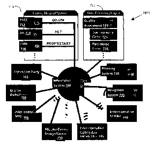
FIG. 7 illustrates how an example informatics system 700, as
disclosed herein, may integrate and manage information from a variety of
sources, in an overall health system 7000. FIG. 7 illustrates the
informatics system 700 in communication with various data sources to
transmit and/or receive information relevant to a patient's treatment.
Although not specifically indicated, it should be understood that such
communication may be two-way, may be wired or wireless communication
(e.g., via wired or wireless networks, such as via an intranet or via the
Internet), may be via removable and fixed media, and may take place
over secure communication channels.
The informatics system 700 may communicate with existing
conventional hospital information systems 710. Existing hospital systems
710 may include databases such as picture archiving and communication
system (PACS) 712, radiology information system (RIS) 714 and
electronic medical records (EMR) 716. The EMR 716, or other databases
(not shown) of the hospital system 710 may store information specific to a
given patient treatment, such as the pathology treated, the treatment
plan used, lab testing carried out, and the treatment outcome, for
example. The databases in the hospital system 710 may communicate
data each in a different format. For example, PACS 712 may store only
DICOM images, RIS 714 may store data according to the HL7 standard,
and EMR 716 may store data in the hospital's own proprietary format.
Traditionally, PACS 712 has served as the primary database and
access point for surgical images. However, it is typically designed in a way
that limits its use in informatics, such as: a) it is typically a flat
database,
27
CA 02942417 2016-09-12
WO 2015/135056
PCT/CA2014/050873
b) it typically only stores DICOM images, and c) its typical primary
purpose is to be an archive of images for radiology.
The informatics system 700 may be used to supplement PACS 712,
and may provide information that is more tailored to the needs of surgical
practitioners. For example, the informatics system 700 may: a) be a
hierarchal database to facilitate grouping data by patient and operation,
b) store DICOM images and additionally other file types, such as non-
DICOM images, videos, PDFs, and XML documents, which may facilitate
grouping image data with non-image data, and c) process data for both
surgery and radiology to extract otherwise difficult-to-discern patterns.
The informatics system 700 may serve as a hub for other data
sources, including proprietary and non-proprietary data sources. FIG. 7
illustrates, as examples, data sources such as a planning system 730,
navigation system 735 (such as the navigation system 205 of FIG. 2),
inter-operative ultrasound 740, inter-operative optics (e.g., exoscope,
Raman, optical coherence tomography (OCT), among others), mobile
device images and/or videos 750, inter-operative imaging such as MRI
755, digital pathology 760 an other data sources, including third-party
proprietary or non-proprietary sources 765.
The data communicated to/from the informatics system 700 may be
of any suitable format, and the informatics system 700 may include
modules or plug-ins to translate data formats for transmission to any
given database.
The informatics system 700 may push data to other databases, and
may provide data to other databases in response to requests. Similarly,
the informatics system 700 may query (or pull) other data sources for
28
CA 02942417 2016-09-12
WO 2015/135056
PCT/CA2014/050873
information, and other data sources may transmit data to the informatics
system 700 without an explicit query. In some examples, the informatics
system 700 may not receive a copy of the data, but rather may simply
reference data that resides in other databases, which may be useful to
reduce bandwidth usage. Referencing data may help avoid data
duplication and re-entry. Such communication of data to/from the
informatics system 700 may provide a rich set of data for analysis by a
data processing engine 720 residing in or external to the informatics
system 700, and described further below. The informatics system 700
may also help to integrate the existing workflow of a hospital system 710
across data sources. For example, the informatics system 700 may be
able to track a RIS imaging order between the RIS 714 and imaging data
sources such as inter-operative ultrasound 740.
The informatics system 700 may communicate with one or more
internal and/or external informatics databases (not shown) that may store
identifying information (e.g., patient identification (ID)) for tracking
patient data across separate data sources, may store copies of data
received from other data sources, and/or may store data in a hierarchy
that can be defined in a way that is relevant for the data processing
engine 720.
The informatics system 700 may also include a local historical
database (not shown), which may store historical data about previous
treatment plans, diagnoses, and outcomes, for example. Historical data
may include, among others, treatment parameters (e.g., region of
interest, patient age, pathology), treatment outcomes, pathology
assessments (e.g., biopsy diagnoses, tissue sample diagnoses), and
29
CA 02942417 2016-09-12
WO 2015/135056
PCT/CA2014/050873
image data. In some examples, the informatics system 700 may, instead
or in addition to a local historical database, access a remote historical
database storing such historical data. The historical data may be cross-
referenced to each other, for example such that the image data and tissue
sample diagnosis for a given treatment plan are all cross-references and
readily identifiable as being related to each other. The informatics system
700 may carry out data processing on historical data, for example using
computer learning algorithms, in order to assist in characterizing and/or
guiding planning and/or diagnosis of a current treatment, as described
further below. The information stored in the historical database may be
tracked, updated and utilized as an adaptive evaluation tool, to search for
similar results (e.g., pathology, imaging and outcomes) in the history of
the same patient, patients with similar imaging/clinical presentations. This
historical database may include information (e.g., patient ID) to assist in
correlation with other databases (e.g., EMR 716) storing patients'
information and medical history.
Once data is received by the informatics system 700, the data
processing engine 720 may be automatically triggered to run various
appropriate processing (e.g., implemented as plug-ins) on the data. The
data processing engine 720 may host various data processing modules or
engines to perform relevant data processing on the data. For example, the
data processing engine 720 may include a quality assessment module 722
for performing quality assessment on image data, a tractography
generator 724 to generate 3D models of neural tracts using data collected
by diffusion tensor imaging (DTI), and a pathology correlator 726, among
others.
CA 02942417 2016-09-12
WO 2015/135056
PCT/CA2014/050873
The pathology correlator 726 may perform pathology correlation to
correlate molecular imaging data (e.g., OCT and Raman imaging), as well
as intraoperative MR imaging, to pathology outcomes, as discussed
further below.
The data processing engine 720 may carry out data processing
locally on the informatics system 700, or may be implemented in a
figurative cloud of remote processors, for example. FIG. 8 is a schematic
illustrating how the data processing engine 720 may distribute data
processing to multiple remote processors 770, via multiple processing
plug-ins 728.
Where the data processing engine 720 is implemented remotely,
this may allow for intense processing to be carried out by remote
processors 770 separate from the informatics system 700, so that the
processing resources of the informatics system 700 itself are not overly
consumed, thus allowing the informatics system 700 to remain responsive
to subsequent user interaction. The data processing engine 720 may also
be implemented using parallel processing across multiple processors 770,
which may allow certain processing tasks to be completed in a fraction of
the time that it would take to perform them on a single processor. This
may enable results to be available to clinicians sooner. The ability to
provide results sooner may be of value during intra-operative image
analysis, where OR time is at a premium.
In some examples, the informatics system 700 may provide output
from the data processing (and optionally the raw data from the data
sources) to the user (e.g., the surgeon) via a web portal, such as an
integrated, thin client web viewers (e.g., an enterprise DICOM viewer or a
31
CA 02942417 2016-09-12
WO 2015/135056
PCT/CA2014/050873
Microsoft Office document viewer). FIG. 9 illustrates an example of how
the informatics system 700 may implement a web portal. In the example
shown, the web portal may be provided via a HTML5-compatible browser,
which may be accessible by desktop and/or mobile devices. The
informatics system 700 may include plug-ins to enable output of various
data types via the web portal. For example, the informatics system 700
may include an enterprise image viewer, a Microsoft Office browser plug-
in, and a PDF browser plug-in to enable viewing of DICOM images,
Microsoft Office documents, and PDF documents, respectively, via the web
portal. The informatics system 700 may also provide output that may be
directly outputted to the web portal, such as analytics generated by the
data processing engine 720.
The web portal may also be used by the user to carry out a search
of data stored by the informatics system 700, for example using a Lucene-
based search. The web portal may also enable the user to carry out a
search of other data sources that is in communication with the informatics
system 700.
In some examples, the informatics system 700 may not be directly
accessible by a user. Rather, the informatics system 700 may only receive
input from and provide output via another existing data source, such as
via the planning system 730 or the navigation system 735. This may help
to restrict user access to the informatics system 700, for security and
privacy purposes, and may also provide the user with a more seamless
integration of information without overwhelming the user.
The informatics system 700 may serve to present information to
the user in a unified format, for example by presenting results (also
32
CA 02942417 2016-09-12
WO 2015/135056
PCT/CA2014/050873
referred to as "analytics") after processing by the data processing engine
720. Such information may be presented in a single, user-friendly web
page, for example.
Although certain plug-ins and modules have been described, it
should be understood that these are non-limiting examples. Any suitable
processing and/or data presentation modules and/or plug-ins may be
implemented, and modules and/or plug-ins may be updated, added or
removed dynamically. Certain modules that are considered clinically
relevant in a certain medical context may be provided with an informatics
system for that medical context. For example, a neurosurgical informatics
system may include modules and plug-ins for managing and interpreting
pre-, intra-, and post-operative imaging data across multiple patients and
procedures, as in the examples described below.
In an example informatics system 700 suitable for a neurosurgical
context, the data processing engine 720 may include a module for
archiving the target and entry locations for a neurosurgical procedure, and
a module for comparing pre- and post-operative white matter
tractography generated from MR DTI acquisitions. Such data analysis
may: provide the surgeon with real-time, historical target/entry
information to assist in treatment planning; to visualize and evaluate
tissue preservation of important nerve fiber bundles following a
neurosurgical procedure, while indicating the entry points that were used;
and possibly to enable determination of correlations between changes in
the patient's tractography and patient outcome. Such data analysis may
be relevant to procedures such as minimally invasive ICH management
and tumor resection.
33
CA 02942417 2016-09-12
WO 2015/135056
PCT/CA2014/050873
FIG. 10A shows an example user interface that may be provided by
the informatics system 700, to assist in treatment planning for a
neurosurgical procedure. This output may be provided to the user via a
web portal, or integrated into conventional treatment planning systems
(e.g., via an appropriate plug-in provided by the informatics system 700).
In this example, the treatment planning involves planning an entry
point to access a surgical target within the brain. The user interface of
FIG. 10A shows an image of the patient's brain, with indicators (in this
example, '+' symbols) indicating historical entry points for accessing the
same or similar targets in historical treatment plans. The circle indicates
the user's currently selected entry point.
FIG. 10B is a flowchart of an example method 1000 for providing
assistance during treatment planning for a neurology procedure (e.g., a
surgical procedure or a drug treatment). Generally, throughout the
present disclosure, neurology procedure may refer to surgical as well as
non-surgical procedures. For simplicity, examples will be described with
reference to a neurosurgical procedure and surgical treatment plane,
however it should be understood that surgical and non-surgical
procedures may both be possible. The method 1000 may be implemented
using a treatment planning module of the data processing engine 720.
Generally, steps described below as being carried out by the informatics
system 700 may more specifically be implemented using a module of the
data processing engine 720.
In some examples, the method 1000 may be provided intra-
operatively as part of the craniotomy procedure (e.g., at block 414 of FIG.
4A) or pre-operatively and the plan imported (e.g., at block 402 of FIG.
34
CA 02942417 2016-09-12
WO 2015/135056
PCT/CA2014/050873
4A). A user may interact directly with the informatics system 700 (e.g.,
via a web portal) to initiate the method 1000, or the interaction may be
via a planning system 730. For example, as a user creates a treatment
plan using the planning system 730, the planning system 730 may
automatically interface with the informatics system 700 to access
analytics to assist in treatment planning. In some examples, the interface
between the planning system 730 and the informatics system 700 may be
entirely hidden from the user, such that the user input to the planning
system 730 is the same as if the informatics system 700 were absent.
At block 1005, the informatics system 700 may receive a set of
data characterizing the neurosurgical procedure. For example, the
informatics system 700 may receive data from the planning system 730
indicating the patient (e.g., a patient ID) and the region of interest or
target site (e.g., a tumor site within the brain).
Optionally, at block 1010, the informatics system 700 may
determine additional data characterizing the neurosurgical procedure. This
may take place where the data received at block 1005 is insufficient for
treatment planning. For example, the informatics system 700 may query
one or more image data sources (e.g., PACS 712, inter-operative MRI
755, inter-operative optics 745 and/or inter-operative ultrasound 740) to
retrieve image data relevant to the site of the neurosurgical procedure. A
patient ID may be used to identify the relevant image data from the
image data sources, for example. The informatics system 700 may also
query the EMR 716 to determine other patient information (e.g., patient
age and treatment history) that may impact the treatment planning.
CA 02942417 2016-09-12
WO 2015/135056
PCT/CA2014/050873
The informatics system 700 may analyze the various data
characterizing the neurosurgical procedure and generate a subset of data
(e.g., patient age, patient gender and target site) characterizing the
neurosurgical procedure.
At block 1015, the informatics system 700 may determine any
relevant historical data, such as historical treatment plans, based on the
subset of data characterizing the neurosurgical procedure. Generally, the
term "historical" may be used in the present disclosure to refer to any
treatment plan previous to the treatment being currently planned.
Determination of historical treatment plans may be carried out by the
informatics system 700 querying its own database of historical data
and/or databases belonging to one or more hospital systems 710.
Generally, historical treatment plans may include treatment plans that
were carried out previously for the current patient or a different patient,
and at the same hospital site or another hospital site.
For example, the informatics system 700 may determine all
historical treatment plans that match the patient age, patient gender,
pathology conditions and region of interest. In some examples, the
informatics system 700 may also filter historical data based on treatment
outcomes, such that only treatment plans associated with desirable
treatment outcomes are considered. In some examples, a nearest
neighbor algorithm may be carried out to determine which historical
treatment plans are relevant (e.g., to determine treatment plans with
similar regions of interest to the currently planned treatment). This may
be more practical than searching for a strict match, since it is unlikely for
36
CA 02942417 2016-09-12
WO 2015/135056
PCT/CA2014/050873
a historical treatment plan to match all characteristics of the current
neurosurgical procedure.
From the relevant historical treatment plans, the informatics system
700 may extract one or more treatment parameters that may assist in
treatment planning. For example, the informatics system 700 may extract
the sulcal entry point from the relevant historical treatment plans. In
another example, the informatics system 700 may determine, for a
current treatment targeting the corpus callosum, one or more historical
trajectories associated with positive patient outcomes.
Although historical treatment plans have been described, the
historical data may include other historical data not in the form of
treatment plans, for example historical outcomes.
At block 1020, the extracted historical treatment parameters may
be outputted to a display device (e.g., a display screen of the planning
system 730). In some examples, the output may be in the form of a user
interface, such as that of FIG. 10A, where the historical treatment
parameters are displayed together with the currently planned treatment
parameter. This may enable the user to easily evaluate whether the
current treatment plan is in line with previous treatment plans. In some
examples, the output may be integrated with the output normally
provided by the planning system 730. For example, the historical
treatment parameters may be displayed superimposed on a conventional
image showing the current treatment plan. In some examples, particular
historical treatment parameter values (e.g., particular historical entry
points) associated with particularly desirable patient outcomes may be
emphasized (e.g., highlighted or colored in green).
37
CA 02942417 2016-09-12
WO 2015/135056
PCT/CA2014/050873
Since treatment planning may take several stages (e.g., planning
entry point, then planning cannulation trajectory), the method 1000 may
be repeated at each treatment planning stage, and for each planned
treatment parameter.
As illustrated in the example above, the informatics system 700
may help the user to visualize and understand correlations between data
from separate data sources. In some examples, the informatics system
700 may provide quantification of traditional qualitative data, to further
assist in analyzing this data.
In some examples, the treatment planning guidance offered by the
informatics system 700 may provide the user with recommended
treatment parameters (e.g., based on relevant historical treatment
parameters that are associated with positive patient outcomes). In other
examples, the treatment planning guidance may be simply informative in
nature, for example by filtering out historical data to only present the user
with the most relevant historical treatment parameters (e.g., filtering
according to the specific treatment type and/or treatment stage, filtering
according to the specific patient or patient type) or by providing the user
with a mapping of historical treatment parameters for different treatment
target locations, without providing any recommendations.
FIG. 11 illustrates an example of how pre- and post-operative
tractography information may be quantified. The informatics system 700
may receive DTI data and use this data to generate a tractograph (e.g.,
using the tractography generator 724 in the data processing engine 720)
to visual represent a patient's neural tracts, both pre- and post-operation.
The informatics system 700 may quantify the tractographs and perform a
38
CA 02942417 2016-09-12
WO 2015/135056
PCT/CA2014/050873
quantitative comparison of the pre- and post-operation tractographs. In
the example of FIG. 11, each tractograph may be quantified by calculating
the fiber volume of particular fiber bundles, such as the superior
longitudinal fasciculus (SLF) and the arcuate fasciculus (AF). A
quantitative comparison may then be made automatically. The informatics
system 700 may also query other data sources (e.g., EMR 716) to
determine the patient outcomes (e.g., vision, motor, cognition, memory,
mortality, etc.) associated with the post-operation tractograph. Similar
quantification and comparisons may be performed for other patient
measurements.
By providing the user with such information, the user may be
provided with feedback for further surgical decisions, as well as valuable
research data.
In some examples, the informatics system 700 may be useful for
tagging and correlating image data with pathological assessment. This
may help the user to identify a pathology visible in a captured image,
based on historical data.
The informatics system 700 may provide the user with a unified
visualization correlating image data with data associated with a tissue
sample. This may be referred to as tagging an image with pathology
information. For example, information about a tissue sample (e.g., patient
ID, sample site) may be stored in the digital pathology database 760. The
informatics system 700 may receive data from both the digital pathology
database 760 and an image data source (e.g., inter-operative optics 745)
and, using data correlation algorithms (e.g., comparing and matching
patient ID), may mark, store, and provide visualization (e.g., as an
39
CA 02942417 2016-09-12
WO 2015/135056
PCT/CA2014/050873
indicator or overlay over a displayed image) of the location at which brain
tissue was resected within pre- and/or intra-operative image data. This
may allow clinicians to more accurately record and recall the anatomical
region of a tissue sample, may help aid in ensuring that the appropriate
tissue was resected, and may serve to categorize and file pathology
results, to be used as input data to other data processing, for example.
Pathology correlation may generally involve evaluating point,
regional, and/or full image data. This may be carried out using the
pathology correlator 726 of the data processing engine 720, for example.
The pathology correlator 726 may also perform a similarity comparison
(e.g., using appropriate algorithms, such as computer learning
algorithms) against historical image data (typically from the same imaging
modality), which may be retrieved from a historical database local to the
informatics system 700 or from a remote database of historical image
data, and which have been associated with known pathology (e.g., as a
result of previous tagging operations, as described above). This image
data may include data from various image data sources, such as Raman
spectroscopy, OCT and hyperspectral imaging, and may also include intra-
operative MR, for example. Such pathology correlation may be carried out
by the informatics system 700 post-operatively and/or intra-operatively
(e.g., during a biopsy procedure).
If the current image data is determined (e.g., using similarity
determination algorithms) to be a close enough match to historical image
data, and that historical data has been tagged with a certain pathology,
then the informatics system 700 may provide indication to the user that
the current image data may share the same pathology. This may provide
CA 02942417 2016-09-12
WO 2015/135056
PCT/CA2014/050873
the user with insight as to what type of tissue they are currently looking
at in an intra-operative context. FIG. 12 shows an example of a user
interface that may be displayed to the user as a result of a pathology
correlation performed by the informatics system 700. In the example
shown, the user may be provided with a real-time view of the tissue
sample site (right image of FIG. 12), with an indicator (e.g., a circle)
showing the tissue sampled. The user may also be provided with an
indicator of a likely pathology for the tissue sample, such as a comparison
of the Raman spectrum of the current tissue sample with the Raman
spectrum of the closest match in historical tissue samples (left image of
FIG. 12). In other examples, rather than providing a chart, the display
may instead provide text or other visual indication of the likely pathology.
This may be useful with Raman and OCT as these are real-time
modalities, meaning a surgeon may be provided with quicker feedback
regarding what type of tissue they are currently viewing. Thus, when a
surgeon uses an OCT or Rama probe to analyze tumor tissue, for
example, and tissue around the tumor margins, the informatics system
700 may use the resulting image signals as "signatures" to be compared
against a database of image "signatures" of known pathologies. The
surgeon may thus be provided with information from intraoperative
analysis of the probed tissue (e.g., whether the tissue is healthy or
diseased tissue). This may be useful for tumor resection procedures, for
example, enabling a surgeon to probe the margins of the tumor to ensure
that the margins are clean of tumor tissue.
Another example of how the informatics system 700 may assist in
diagnosis of a pathology is shown with respect to FIGS. 5A and 5B.
41
CA 02942417 2016-09-12
WO 2015/135056
PCT/CA2014/050873
FIG. 5A illustrates an example user interface provided by the
informatics system 700. The example display provides the user with
information pertaining to one or more similar tissue analyses (e.g., based
on a comparison with historical data, as described above), and may be
provided in response to the selection of a reference marker in a current
image. In the example of FIGS. 5A and 5B, the user interface shows an
image of a patient's brain 530, including a tumor 532. The image may be
obtained using any suitable imaging modality, such as MR. The user
interface may be displayed in real-time as the patient's brain is being
examined (e.g., as part of a tissue sampling procedure). The image may
include one or more reference markers 540, 541, 542, which may
correspond to locations of interest (e.g., locations where tissue samples
were obtained). The display may provide an overlay 585 when a reference
marker 540 is selected. In response to this selection, the informatics
system 700 may automatically carry out a comparison of data associated
with tissue at the location of the reference marker 540 with historical
tissue data. The overlay 585 may show the results of this comparison,
including various forms of tissue information pertaining to one or more
similar historical tissue analyses. The tissue information that may be
displayed include pathology data associated with similar prior tissue
analyses, outcome data associated with similar prior tissue analyses,
and/or diagnosis data associated with similar prior tissue analyses, among
others. FIG. 5B shows another example overlay 590, in which local tissue
diagnostic data associated with similar historical tissue analyses may be
presented to the user.
42
CA 02942417 2016-09-12
WO 2015/135056
PCT/CA2014/050873
As noted above, in some embodiments, tissue information
pertaining to prior tissue analyses may be provided, based on a
determination of similarity (e.g., using suitable comparison algorithms).
The determination of similarity may be based not only on the tissue data,
but also other information related to the procedure, such as patient age
and/or hospital site. The determination of similar historical data may be
based on a comparison between local tissue diagnostic data associated
with the current patient, and historical local tissue diagnostic data
obtained from a historical tissue analysis database.
An example illustration of different stages of a surgical procedure,
and their association to one or more tissue analysis databases, is shown in
FIG. 5C. The figure shows an example embodiment involving four stages
of decision-making, namely diagnostic evaluation 505, surgical planning
510, intra-operative surgery, diagnosis or treatment 515, and
postoperative analysis 520. These stages are shown in their relation to
each other, and with regard to the informatics system 700, which can be
accessed during one or more stages of a medical procedure. In the
example shown, informatics system 700 may include a tissue
identification/analysis database 500, storing historical tissue identification
and analyses. In some examples, the tissue identification/analysis
database 500 may be remote from the informatics system 700 and may
be queried by the informatics system 700 when appropriate. In this
example, four aspects of patient care, where the use of a database linking
registered imaging, pathology and outcomes can be utilized to improve
diagnosis, surgical planning, surgical tissue differentiation and treatment
and postoperative decision-making.
43
CA 02942417 2016-09-12
WO 2015/135056
PCT/CA2014/050873
In the example workflow shown in FIG. 5C, the diagnostic
modalities listed, include, but are not limited to, a set of whole organ,
regional, or local diagnostic modalities, which may include imaging
modalities such as, magnetic resonance Imaging (MRI), computerized
tomography (CT), positron emission tomography (PET), SPECT, ultrasound
(US), x-ray, optical (visible light or sections of full EM spectrum), optical
coherence tomography (OCT), photo-acoustic (PA) or regional imaging
modalities. These modalities can be acquired and shown as 1D, 2D, 3D, or
4D (3D+time), data sets, and may be registered to the patient in a
dimensionally and positionally accurate manner. Biopsy methods include
core or endoscopic biopsy, surgical biopsy (large section), aspiration, or
other methods of removing tissue of interest for further pathology
analysis.
FIG. 6, is a flow chart showing an example method for correlating a
local tissue diagnostic measurement with historical tissue analysis data.
The example method may be performed by the pathology correlator 726
of the data processing engine 720, for example. The example method may
be carried out real-time during a procedure.
At step 600, local tissue diagnostic data is obtained. The local tissue
diagnostic data may be associated with one or more local tissue diagnostic
measurements performed on a subject.
For example, the local tissue diagnostic data may be local imaging
data, such as a MR image obtained via an insertable MR probe, or local
non-imaging data, such as locally measured Raman spectrum. In cases
where this local tissue diagnostic data may not be sufficient to perform
tissue analysis, the informatics system 700 may retrieve additional
44
CA 02942417 2016-09-12
WO 2015/135056
PCT/CA2014/050873
information (e.g., other information about the same patient) from other
databases to supplement and complete the diagnostic data. For example,
the informatics system 700 may perform correlation of the local tissue
diagnostic data with historical local tissue diagnostic data from prior tissue
analyses from the same or other patient. In cases in which the local tissue
diagnostic data pertains to measurements made with more than one
diagnostic modality, the location at which each local tissue analysis is
made may be recorded, optionally along with a time stamp. The location
information may be employed to correlate local tissue diagnostic data
obtained for a common tissue location, but with different diagnostic
modalities, for example.
At step 605, historical local tissue diagnostic data and tissue
analysis data associated with one or more prior local tissue analyses is
accessed (e.g., from the tissue identification/analysis database 500) or
otherwise obtained. Tissue analysis data may include information
including, but not limited to, one or more of pathology data, outcome
data, tissue identification data, and/or diagnosis data.
At step 610, the local tissue diagnostic data associated with the one
or more local tissue diagnostic measurements, and the historical local
tissue diagnostic data associated with the one or more prior local tissue
analyses, may be compared. The comparison may be performed according
to certain similarity criteria, such as similarity of region of interest
(e.g.,
target surgical site), similarity of patient characteristics, and similarity
of
diagnostic data. Appropriate algorithms (e.g., nearest neighbor) may be
used by the data processing engine 720 to carry out such comparisons.
CA 02942417 2016-09-12
WO 2015/135056
PCT/CA2014/050873
The historical tissue diagnostic data may be searched for a close
match with the current tissue diagnostic data. The search may be limited
to historical data from the same diagnostic modality as the current data.
Non-limited example of diagnostic modalities include MRI (Ti, T2, DWI,
ADC, FA, SWI, MRS), CT, Ultrasound, SPECT, PET, Raman spectroscopy,
OCT, histological staining and high resolution optical imaging (microscopy
and otherwise). For example, if the local tissue diagnostic data obtained
for the subject includes a Raman spectrum, the tissue
identification/analysis database 500 may the searched to find historical
local tissue diagnostic data that was also measured via Raman
spectroscopy (where the archived Raman spectra are stored correlated
with tissue analysis data), and the measured Raman spectrum for the
current patient may be compared with the historical Raman spectrum to
find a prior tissue analysis having a similar Raman spectrum.
At step 615, one or more historical local tissue analyses associated
with one or more closest matching tissue diagnostic data are identified,
thereby identifying a prior tissue analysis that may relevant to analysis of
the local tissue region of the current subject. Information about the
closest matching historical tissue identification, diagnosis and/or analyses
may be outputted to the user, for example as a visual display (e.g., as in
the user interfaces of FIGS. 12, 5A and 56, described above).
Generally, data in the tissue identification/analysis database 500
may be the result of multiple tissue analyses (e.g. for the same subject,
or for different subjects) stored in the data base 500 (or other suitable
data structure) as local tissue diagnostic data obtained from local tissue
diagnostic measurements and associated tissue analysis data.
46
CA 02942417 2016-09-12
WO 2015/135056
PCT/CA2014/050873
For example, one entry in the tissue identification/analysis database
500 may be constructed as follows, in which multiple diagnostic modalities
are employed to interrogate a local tissue region of a subject (although it
will be understood that an entry or data element may include diagnostic
data from a single diagnostic modality). In the present example, three
different diagnostic modalities are employed. A tracked Raman
spectroscopy probe is employed to correlate the location the local tissue
region with its Raman spectrum. Intra-operative MRI may also be
employed to obtain MRI diagnostic data, where the use of a tracking
and/or navigation system will allow the obtained MRI data to be correlated
with the Raman spectrum. Finally, a tracked optical imaging device may
be employed to optically interrogate the local tissue region, allowing the
visual appearance of the tissue to be correlated with the Raman and MR
data.
The local tissue diagnostic data associated with these
measurements is stored, in the database 500 (or other suitable data
structure), along with, or correlated with, tissue analysis data pertaining
to the local region. The tissue analysis data may include pathology data.
For example, if a tissue sample from the local tissue region is excised and
sent to a pathology laboratory, the pathology results (which may include
cell type, microscope image, tissue imaging (for example, X-ray, MRI))
may be correlated, as tissue analysis data, with the local tissue diagnostic
data that was intra-operatively obtained, and stored as an entry in the
tissue database 500.
As described below, other types of tissue analysis data may
additionally or alternatively be correlated with the local tissue diagnostic
47
CA 02942417 2016-09-12
WO 2015/135056
PCT/CA2014/050873
data to form the entry (e.g. database element) of the tissue analysis
database 500. Examples of other tissue analysis data include, but are not
limited to, outcome data (e.g. pertaining to the outcome of a medical
procedure during which the local tissue diagnostic data was obtained),
diagnosis data (e.g. pertaining to the diagnosis of a given pathology), and
additional data pertaining to the subject (such as, but not limited to,
demographic data, genetic data, and/or medical history data).
In some example embodiments, the diagnostic data from two or
more different diagnostic modalities may be employed allow for improved
tissue analysis, as the same tissue region can be measured using multiple
tissue analyses.
The tissue identification/analysis database 500, which, as noted
above, includes tissue analysis data from prior tissue analyses, may be
used by the informatics system 700 to guide, or suggest, which diagnostic
modalities should or could be employed when performing medical
procedures (e.g. surgical tissue resection procedures) involving known
types of tissue. For example, if tissue resection of a known tissue type
(e.g. a known tumor type) is to be performed, then the informatics
system 700 may query the tissue identification/analysis database 500 to
identify any prior tissue analyses corresponding to the particular tissue
type of interest, in order to identify diagnostic modalities that have been
shown to have local tissue diagnostic data that is correlated with a given
tissue type. The identified diagnostic modalities may then be employed by
the surgeon during the tissue resection procedure, and the local tissue
diagnostic data that is intra-operatively obtained may be compared with
the archival local tissue diagnostic data to intra-operatively identify
48
CA 02942417 2016-09-12
WO 2015/135056
PCT/CA2014/050873
exposed tissue. In some examples, the tissue identification/analysis
database 500 may include only tissue diagnostic data that is correlated
with the tissue analysis data (e.g. such that local tissue diagnostic data
that did not show features or a signature associated with the tissue type is
excluded).
Although the present disclosure describes the operation of the
informatics system with certain data processing modules, it should be
understood that the informatics system may include other modules. The
informatics system may be repeated updated and/or modified by the
update, addition and/or removal of modules. Generally, each module may
provide the functions of scouring large amounts of data, and distilling
them into user-friendly outputs.
Any information stored locally by the informatics system may be
modified to anonymize the data (e.g., by removal of patient-sensitive
data). This may be carried out automatically by the informatics system.
When the informatics system presents information to a user, where the
information may be derived from remote data sources, the presented
information may be similarly anonymized.
The informatics system may serve as a central hub for multiple
hospital sites, and may facilitate sharing of data across different hospital
sites via the central hub. Alternatively, each hospital may have its own
installation of the informatics system (and optionally each hospital may
have more two or more installations of the informatics system, such as for
different wings of the hospital), and the common platform offered by the
informatics system may facilitate sharing of data across different hospital
sites. Where there are two or more installations of the informatics system
49
CA 02942417 2016-09-12
WO 2015/135056
PCT/CA2014/050873
in operation in the health system, it may be possible to amalgamate or
consolidate multiple installations of the informatics system together. This
may be via an automated synchronization mechanism on each installation
that propagates changes from a more recent installation or the older
installation (or vice versa), or via a third installation that simply holds
references to the two existing installations. This may result in a web-like
or tree-like structure of multiple informatics systems.
The amalgamation of data via a central informatics system or a
web/tree of informatics systems may facilitate collaboration between
surgeons across different hospitals and even within the same hospital.
This may enable knowledge and experience of a single surgeon to be
accessible by multiple other surgeons. The present disclosure may also be
used to provide training and/or proctoring, even remotely. Further, since
the knowledge and experience of a surgeon may be distilled in the
treatment of their patients, this knowledge and experience may be
accessed (in the form of historical treatment plans) without undue burden
on the surgeon.
Although the present disclosure discusses treatment planning for
treatment of a brain tumor, in various examples, it should be understood
that the present disclosure may be applicable to other surgical and non-
surgical procedures. For example, the present disclosure may be
applicable to any neurology procedure, including surgical procedures,
pharmaceutical treatments, and combination surgical/pharmaceutical
treatments.
While some embodiments or aspects of the present disclosure may
be implemented in fully functioning computers and computer systems,
CA 02942417 2016-09-12
WO 2015/135056
PCT/CA2014/050873
other embodiments or aspects may be capable of being distributed as a
computing product in a variety of forms and may be capable of being
applied regardless of the particular type of machine or computer readable
media used to actually effect the distribution.
At least some aspects disclosed may be embodied, at least in part,
in software. That is, some disclosed techniques and methods may be
carried out in a computer system or other data processing system in
response to its processor, such as a microprocessor, executing sequences
of instructions contained in a memory, such as ROM, volatile RAM, non-
volatile memory, cache or a remote storage device.
A computer readable storage medium may be used to store
software and data which when executed by a data processing system
causes the system to perform various methods or techniques of the
present disclosure. The executable software and data may be stored in
various places including for example ROM, volatile RAM, non-volatile
memory and/or cache. Portions of this software and/or data may be
stored in any one of these storage devices.
Examples of computer-readable storage media may include, but are
not limited to, recordable and non-recordable type media such as volatile
and non-volatile memory devices, read only memory (ROM), random
access memory (RAM), flash memory devices, floppy and other removable
disks, magnetic disk storage media, optical storage media (e.g., compact
discs (CDs), digital versatile disks (DVDs), etc.), among others. The
instructions can be embodied in digital and analog communication links for
electrical, optical, acoustical or other forms of propagated signals, such as
carrier waves, infrared signals, digital signals, and the like. The storage
51
CA 02942417 2016-09-12
WO 2015/135056
PCT/CA2014/050873
medium may be the internet cloud, or a computer readable storage
medium such as a disc.
Furthermore, at least some of the methods described herein may
be capable of being distributed in a computer program product comprising
a computer readable medium that bears computer usable instructions for
execution by one or more processors, to perform aspects of the methods
described. The medium may be provided in various forms such as, but not
limited to, one or more diskettes, compact disks, tapes, chips, USB keys,
external hard drives, wire-line transmissions, satellite transmissions,
internet transmissions or downloads, magnetic and electronic storage
media, digital and analog signals, and the like. The computer useable
instructions may also be in various forms, including compiled and non-
compiled code.
At least some of the elements of the systems described herein may
be implemented by software, or a combination of software and hardware.
Elements of the system that are implemented via software may be written
in a high-level procedural language such as object oriented programming
or a scripting language. Accordingly, the program code may be written in
C, C++, 3++, or any other suitable programming language and may
comprise modules or classes, as is known to those skilled in object
oriented programming. At least some of the elements of the system that
are implemented via software may be written in assembly language,
machine language or firmware as needed. In either case, the program
code can be stored on storage media or on a computer readable medium
that is readable by a general or special purpose programmable computing
device having a processor, an operating system and the associated
52
CA 02942417 2016-09-12
WO 2015/135056
PCT/CA2014/050873
hardware and software that is necessary to implement the functionality of
at least one of the embodiments described herein. The program code,
when read by the computing device, configures the computing device to
operate in a new, specific and predefined manner in order to perform at
least one of the methods described herein.
While the teachings described herein are in conjunction with various
embodiments for illustrative purposes, it is not intended that the
teachings be limited to such embodiments. On the contrary, the teachings
described and illustrated herein encompass various alternatives,
modifications, and equivalents, without departing from the described
embodiments, the general scope of which is defined in the appended
claims. Except to the extent necessary or inherent in the processes
themselves, no particular order to steps or stages of methods or
processes described in this disclosure is intended or implied. In many
cases the order of process steps may be varied without changing the
purpose, effect, or import of the methods described.
53