Note: Descriptions are shown in the official language in which they were submitted.
CA 02942531 2016-09-12
WO 2015/137984
PCT/US2014/031051
DUAL/VARIABLE GAIN OIL PUMP CONTROL VALVE
FIELD OF INVENTION
[0001] The present invention relates to an electromagnetic solenoid
actuator having an armature mechanism that drives a fluid control element.
BACKGROUND
[0002] Direct acting solenoid actuators are often used to control fluid
pressure in a variety of systems, including clutch mechanisms and other
devices in an automobile. Direct acting solenoid actuators employ an
armature mechanism that drives a fluid control element, such as a spool, a
spring-biased four-way proportional flow control valve, a poppet valve, and
the
like in various hydraulic control applications. Typically, the armature is
connected to, and drives, a push pin that engages the fluid control element to
this end.
[0003] The fluid control element may comprise a spool surrounded by a
valve body. The spool may be connected to the push pin such that any motion
of the armature results in motion of the spool. The position of the spool, and
the resulting fluid pressure, are directly dependent on the position of the
armature. The coil, therefore, must produce a sufficiently strong magnetic
field to move the spool under any pressure condition. To achieve this, the
coil
may require many loops, dictating the size of the apparatus and requiring a
large quantity of copper wiring.
SUMMARY
[0004] A solenoid fluid control valve is disclosed for controlling a
variable displacement pump. The solenoid fluid control valve comprises a
fixed solenoid component, a movable armature component, a fixed nozzle body,
a movable spool within the fixed nozzle body, and a valve member. The valve
member regulates fluid pressure in a first and second feedback chamber.
Fluid in the second feedback chamber establishes a second feedback pressure
that acts on the movable spool with a motive feedback force in a first axial
-1-
CA 02942531 2016-09-12
WO 2015/137984
PCT/1JS2014/031051
direction. The movable spool moves in the first axial direction in response to
the motive feedback force.
BRIEF DESCRIPTION OF THE DRAWINGS
[0005] Figure 1 shows a direct acting solenoid fluid control valve;
[0006] Figure 2 shows a dual gain solenoid fluid control valve in a de-
energized state;
[0007] Figure 3 shows the dual gain solenoid fluid control valve in an
energized state;
[0008] Figure 4 illustrates a cross-section of the dual gain solenoid fluid
control valve shown in Figure 3;
[0009] Figure 5 shows an exhaust path for fluid in the outer feedback
chamber;
[0010] Figure 6 shows a continuation of the exhaust path in a cross-
section of the dual gain solenoid fluid control valve shown in Figure 5;
[0011] Figure 7 shows a second embodiment of the dual gain solenoid
fluid control valve in a de-energized state; and
[0012] Figure 8 shows the second embodiment of the dual gain solenoid
fluid control valve in an energized state.
DETAILED DESCRIPTION OF THE PREFERRED EMBODIMENT(S)
[0013] A direct acting solenoid fluid control valve is shown in Figure 1.
The direct acting solenoid fluid control valve 100 comprises a housing 102
containing a bobbin 104, and a coil of wire 106 wound on the bobbin 104 and
connected to electrical terminals 108. An armature 110 moves in response to
a current through the coil 106. The reduced diameter end of the armature 110
is fixed to the adjacent end of a spool 112. A nozzle body 114 includes a
supply
port 116; a control port 118; and an exhaust port 120. The spool 112 is moved
in response to movement of the armature 110 to regulate pressure or flow at
the control port 118. The spool 112, and thus the armature 110, is biased by a
spring mechanism 122.
-2-
[0014] For an initially high pressure solenoid fluid control valve, the
control port 118 is open to the supply port 116, as shown in Figure 1.
Supplying power to the coil 106 causes the armature 110 to move in the
direction of the spring mechanism 122, displacing the spool 112 and
connecting the control port 118 to the exhaust port 120, thereby reducing the
pressure at the control port. The pressure at the control port 118 therefore
directly depends upon the position of the spool 112, and accordingly, the
position of the armature 110. The force on the armature 110 induced by the
current through the coil 106 must be sufficiently strong to displace the spool
and compress the spring mechanism 122. For a large spool, this may require
many turns of the coil 106, contributing to the device's size, weight, and
cost.
[0014a] Approaches taken to decrease the device's size, weight, and cost,
include using a spool/piston assembly and slidably mounting a piston on one
or both ends of a spool such that it is independently returnable to an initial
position, as described by U.S. Pat. No. 4,245,671 to Kosugui. The apparatus,
however, is operated by fluid pressure in a pilot chamber, wherein the piston
is independently returnable upon relieving the pilot chamber of fluid
pressure.
Moreover, the apparatus does not include a second feedback chamber having a
radial space between an inner surface of an end of a fixed nozzle body and an
outer surface of the piston that increases the contacting area that the fluid
acts on.
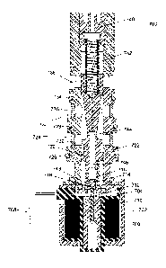
[0015] A dual gain solenoid fluid control valve is shown in Figure 2.
The
dual gain solenoid fluid control valve 200 comprises a housing 202 containing
a bobbin 204, and a coil of wire 206 wound on the bobbin 204 and connected to
electrical terminals 208. An armature 210 moves in response to a current
through the coil 206. The armature may be fixed to an actuator pin 212.
[0016] A valve member 214 is located within a piston 216, and seals an
opening 218 in the piston 216 when the coil 206 is in the de-energized state.
This state is shown in Figure 2. An end of the spool 220 fits into an end of
the
piston 216 opposite the opening 218. A nozzle body 222 surrounds the spool
220 and the piston 216. The nozzle body 222 includes supply port 224 defined
between 0-ring seals 226 and 228 and protected by filter 230; control port 232
-3-
CA 2942531 2018-04-13
defined between 0-ring seals 228 and 234 and protected by filter 236; and
exhaust port 238. The spool 220 is moved to regulate pressure at the control
port 232. A calibration cap 240 fits into the end of the nozzle body 222
opposite the armature 210. The calibration cap 240 may be tightened or
loosened to change the force of the spring mechanism 242 on the spool 220.
[0017] In one
embodiment of the invention, the spool 220 includes a
radial spool bore 244 and longitudinal spool bore 246 that connect the supply
port 224 to the piston chamber 248. The combined space in the longitudinal
spool bore 246 and piston chamber 248 is referred to herein as the inner
feedback chamber 246, 248. When the coil 206 is in the de-energized state,
-3a-
2931537-1
CA 2942531 2018-04-13
CA 02942531 2016-09-12
WO 2015/137984
PCT/US2014/031051
fluid from the supply port 224 fills the inner feedback chamber 246, 248 and
exerts a first feedback force on the spool 220 that balances the force of the
spring mechanism 242. The first feedback force depends on the supply
pressure and the axial fluid contracting area of the inner feedback chamber
246, 248. In the de-energized state, the supply port 224 communicates to the
control port 232, as shown in Figure 2.
[0018] Figure 3 shows the solenoid fluid control valve 300 in the
energized state, wherein like numbers in as in Figure 2 correspond to like
elements. When the coil 306 is energized, the armature 310 and pushpin 312
move axially, displacing the valve member 314 from the opening 318 in the
piston 316. Fluid in the inner feedback chamber 346, 348 flows through the
opening 318 and into the outer feedback chamber 350. Because the outer
feedback chamber 350 increases considerably the contacting area that the
fluid acts on in addition to the inner feedback area 346, 348, the fluid now
exerts a much larger force on the spool 320. This force now exceeds the
opposing force of the spring mechanism 342, and the spool 320 moves toward
the spring mechanism 342, into the position shown in Figure 3. In this state,
the control port 332 communicates to the exhaust port 338, reducing the
pressure at the control port (i.e., control pressure).
[0019] Figure 4 shows a cross-sectional view of the dual gain solenoid
fluid control valve. The view is taken from the position of the dashed line
352
in Figure 3, although the valve member 314 is not shown. Referring to Figure
4, the nozzle body 400 surrounds the cylindrical piston wall 402, which is
fixed
to the rectangular piston base 404. A hole 406 in the piston base 404 is
sufficiently wide to permit fluid to exit the inner feedback area while the
pushpin 408 extends through the hole 406. The fluid passes under the piston
base 404 and through the opening 410 between the rectangular piston base
404 and the cylindrical nozzle body 400, into the outer feedback chamber.
[0020] Referring now to Figure 5, when the coil 500 is returned to its de-
energized state, fluid in the inner feedback chamber 516 and outer feedback
chamber 506 exerts a force on the armature 502 and valve member 504,
returning them to their initial position. Fluid from the outer feedback
-4-
CA 02942531 2016-09-12
WO 2015/137984
PCT/US2014/031051
chamber 506 exits through an exhaust port (not shown). The fluid path is
indicated by arrows. The fluid travels between the cylindrical nozzle body 508
and rectangular piston base 510. It then travels under the piston base 510
and through a hole in the washer 512.
[0021] Figure 6 shows a cross-sectional view of the solenoid fluid control
valve taken at the dashed line 514 in Figure 5. As illustrated by the arrows
in
Figure 6, fluid travels from an inner to an outer area between the washer and
the bobbin and exits through an exhaust port 600. The departure of fluid from
the outer feedback chamber reduces the pressure in that area, allowing the
spool to return to its initial position.
[0022] Returning to Figure 3, the dual gain solenoid fluid control valve
300 requires less force from the coil 306 than the direct acting solenoid
fluid
control valve of Figure 1 requires. The force from the coil 306 is only
required
to displace the valve member 314 from the opening in 318 in the piston 316.
Once the valve member 314 is displaced, fluid in the inner feedback chamber
346, 348 and outer feedback chamber 350 provides the force that displaces the
spool 220 and compresses the spring mechanism 242.
[0023] In contrast, the force from the coil 106 in the direct acting
solenoid fluid control valve 100 shown in Figure 1 must be sufficient to
displace the entire spool 112 and compress the spring mechanism 122. This
greater force requires more turns of the coil 106, resulting in a larger, more
expensive device. The dual gain solenoid fluid control valve utilizes the
fluid
pressure in the inner and outer feedback chambers to move the spool, thereby
requiring fewer turns of the coil, and therefore allowing for a reduction in
the
device's size and cost.
[0024] The dual gain solenoid fluid control valve has a further
advantage of improved robustness to contamination. Contamination can
greatly affect the performance of a solenoid fluid control valve, as small
contaminants in the fluid flowing through the valve may become lodged
between moving and stationary elements, obstructing the smooth motion of
the armature and spool. This obstruction may lead to hysteresis, as well as to
variable responses to a given command current. Accordingly, the presence of
-5-
CA 02942531 2016-09-12
WO 2015/137984
PCT/US2014/031051
contaminants may quickly degrade the solenoid fluid control valve's
performance and reliability.
[0025] The first and second feedback chambers of the dual gain solenoid
fluid control valve allow fluid to travel through wide passages within the
device. The fluid may carry contaminants, but the wide chambers allow the
valve to function without being inhibited by the contaminants. This increased
robustness improves the reliability of the device, allowing for look-up tables
to
be created relating a current in the coil for a resulting control pressure.
The
lifetime of the device may also be extended as wear due to contaminants is
minimized.
[0026] While the dual gain solenoid fluid control valve may be used as
an on/off switch for the control pressure, a pulse width modulated (PWM)
signal may be used to provide variations in the control pressure. The spring
cap may be tightened or loosened to adjust the position of the spool in the
energized and de-energized states. Once the two positions have been
determined, the duty cycle of the PWM signal may determine how much time
the solenoid spends in each state, thereby creating a variable control
pressure.
[0027] Another embodiment of the dual gain solenoid fluid control valve
is shown in Figures 7 and 8, wherein like numbers as in Figures 2 and 3
indicate like elements. Referring to Figure 7, the dual gain solenoid fluid
control valve 700 is in the de-energized state. In this embodiment, the radial
spool bore 744 is moved to a tapered region of the spool 720. In the de-
energized state, the radial spool bore 744 is open to the supply port 724 and
the control port 732.
[0028] Referring to Figure 8, when the coil 806 is energized, the dual
feedback from the inner feedback chamber 846, 848 and outer feedback
chambers 850 moves the spool such that the radial spool bore 844 is open to
the supply port 832 and the exhaust port 838. However, as in the first
embodiment of the dual gain solenoid fluid control valve, the calibration cap
840 may be tightened or loosened to adjust the force of the spring mechanism
842 on the spool 820. This force in turn determines the position of the spool
820 when the coil 806 is in the de-energized and energized states.
Accordingly,
-6-
CA 02942531 2016-09-12
WO 2015/137984
PCT/US2014/031051
the spool position in the de-energized and energized states may not exactly
correspond to the positions shown in Figures 7 and 8.
[0029] Referring to Figure 8, the inner and outer feedback pressure now
depends on both the supply and control pressures, and not just the supply
pressure. Further, the placement of the radial spool bore 844 allows the
device to be configured such that a small control pressure remains even when
the coil 806 is energized, and the control pressure it at a minimum. Having a
non-zero minimum control pressure allows the valve to be more responsive to
a change in the current through the coil. This improved response allows the
valve to be more accurately controlled by a PWM signal.
[0030] The dual gain solenoid fluid control valve may be used to control
a variable displacement pump, wherein the valve's control pressure regulates
the flow of fluid through the pump. The pump requires that the valve's
response to a given command current be accurate and reliable, so that the
command current may be correlated with a flow through the pump. The dual
gain solenoid fluid control valve provides a reliable control pressure that is
robust to contamination and responsive to small changes in the command
current.
-7-