Note: Descriptions are shown in the official language in which they were submitted.
81799545
MICROFLUIDIC DEVICE
[0001] The subject application claims priority to US provisional
Application No.
61/984,213, filed April 25, 2014.
FIELD OF THE INVENTION
[0002] The present invention relates to the field of disposable, multi-
purpose
diagnostic tests and to methods of manufacturing the same.
BACKGROUND OF THE INVENTION
[0003] In the past several years, paper-based devices have emerged as
inexpensive platforms for simple qualitative and semi-quantitative
colorimetric assays.
See, for example, Li, X. et al., Biomicrofluidics, 2012,6, 11301. For example,
three-
dimensional (3D) structures have been developed that allow for the measurement
of
multiple analytes on a single device. See, for example, Martinez, A.W. et al.,
Proc Natl
Acad Sci 2008, 105, 19606). Recently, devices have been developed that enclose
a
reaction site with printing toner yielding an assay that is protected from the
environment,
and is more akin to conventional plastic-based microfluidic devices. See, for
example,
Schilling K.M. et al., Anal Chem, 2012, 84, 1579. However, this device is
complicated in
structure, is difficult to use, and requires significant amount of time (>60
min) to
construct. In addition, yellow toner is required to be printed over the
reaction/detection
area to enclose Schilling's device. The yellow colorant may interfere with the
chemistries
of other reactions, may mask or alter the true color of a result, and thus may
render
analysis more difficult. Further, the device described by Schilling, et al.
does not enable
assay expansion with ease; therefore, its utility is limited.
[0004] A laminated self-powered, electrochemical device has also been
reported
by Liu et al. (Angew Chem. Int. Ed., 2012, 51, 1). This device is referred to
as an
"origami paper analytical device (oPAD)," and is based on a chemical reaction
yielding a
measurable current as a function of analyte concentration. This device is also
complicated to make (includes many steps, layers, and is time consuming),
requires
folding steps, and requires a four sided process to laminate the structure. In
addition, it
1
Date recue/Date Received 2021-02-17
81799545
may take approximately 10 minutes for a sample to fill the device before a
measurement
can take place for a single analyte. This time period is often too long for
time-sensitive
diagnostics.
SUMMARY OF THE INVENTION
[0004a] According to one aspect of the present invention, there is
provided a
microfluidic device comprising: a porous substrate, the porous substrate
comprising a
first side and a second side; a plurality of reaction channels disposed on the
first side of
the porous substrate, the plurality of reaction channels being disposed on the
first side of
the porous substrate in a user-defined pattern, each reaction channel of the
plurality of
reaction channels comprising at least one boundary comprising at least one
barrier
material, the at least one boundary comprising at least a bottom boundary
comprising the
at least one barrier material; and at least one reagent disposed within each
reaction
channel of the plurality of reaction channels to provide a colorimetric
analysis of at least
one analyte or property in a sample introduced to the microfluidic device,
wherein the
microfluidic device comprises a housing comprising a first backing comprising
at least a
first aperture defined therein and a plurality of second apertures positioned
over the
plurality of reaction channels, and a second backing.
[0004b] According to another aspect of the present invention, there is
provided A
method of manufacturing a microfluidic device comprising: defining at least
one reaction
channel on a first side of a porous substrate by disposing the at least one
reaction
channel on the first side of the porous substrate in a pattern, the at least
one reaction
channel comprising at least one boundary comprising at least one barrier
material, the at
least one boundary comprising at least a bottom boundary comprising the at
least one
barrier material; disposing at least one reagent within the at least one
reaction channel
wherein the at least one reagent provides a colorimetric analysis of a
predetermined
analyte or property of a sample; forming at least one first aperture and at
least one
second aperture in at least one of a first backing or a second backing of a
laminate
structure, the at least one second aperture being disposed over the at least
one reaction
channel, wherein upon lamination, the first aperture serves as a sample port
for the
microfluidic device and the second aperture serves as a vent for the
microfluidic device;
2
Date recue/Date Received 2021-02-17
81799545
and laminating the porous substrate within the laminate structure to form an
enclosed
microfluidic device.
BRIEF DESCRIPTION OF THE DRAWINGS
[0005] The invention is explained in the following description in view of
the
drawings that show:
[0006] FIG. 1 illustrates a microfluidic device in accordance with an
aspect of the
present invention.
[0007] FIG. 2 illustrates a microfluidic device having a backing in
accordance with
another aspect of the present invention.
[0008] FIG. 3 illustrates an enclosed laminated microfluidic device in
accordance
with another aspect of the present invention.
[0009] FIG. 4 illustrates a two-sided microfluidic device in accordance
with yet
another aspect of the present invention.
[0010] FIG. 5 is an exploded view of a three-dimensional microfluidic
device in
accordance with yet another aspect of the present invention.
[0011] FIG. 6 comprises a side view of the microfluidic device of FIG. 5
upon
lamination in accordance with yet another aspect of the present invention.
DETAILED DESCRIPTION OF THE INVENTION
[0012] Aspects of the present invention are directed to an easily
produced,
customizable microfluidic device. The device may be utilized for health-
related
diagnostic tests such as medical diagnosis, water quality, food quality, and
the like.
Advantageously, the device may be formed from inexpensive consumer products
such
that the device may be quickly manufactured and utilized where resources are
limited.
These devices are not only inexpensively constructed from low cost materials
and are
simple to manufacture, but are also highly flexible (in terms of assay
expansion), may
withstand exposure to a wide range of environmental conditions, require only
small
sample sizes, and provide fast results.
2a
Date recue/Date Received 2021-02-17
CA 02942535 2016-09-12
WO 2015/164112
PCT/US2015/025554
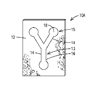
[0013] Referring now to FIG. 1, FIG. 1 illustrates a device10 in accordance
with an aspect of the present invention that is simple to construct and allows
for
multiple assays. The device 10A comprises a substrate 12 and at least one
reaction
channel 14 defined on a first side of the substrate 12 in a pattern 13. At
least a
portion of boundary of the reaction channel 14 is defined by a barrier
defining
material 16 (hereinafter "barrier material 16"), which acts as a barrier for a
sample
and defines at least a portion of a perimeter or an outer boundary of each
reaction
channel 14. In one aspect, the barrier material 16 may have a lower porosity
and/or
a higher degree of hydrophobicity than the substrate 12 so as to maintain an
aqueous or a hydrophilic sample within its boundaries. At least one reagent 18
is
disposed within at least a portion the reaction channel 14 at a reaction site
15 in an
amount effective to indicate the presence of a predetermined analyte or the
presence of a property in a sample, e.g., a test sample, which is introduced
into the
device 10A. In certain embodiments, the reagent 18 is useful for colorimetric
indication of the presence of one or more predetermined analytes or one or
more
properties in a sample, such as a colorimetric indication of glucose levels in
a
biological sample.
[0014] In certain embodiments, the substrate 12 is self-supporting. In
other
embodiments, the device 10B comprises a substrate 12 coupled with a backing 20
as shown in FIG. 2. The backing 20 may be formed from a liquid impermeable
material, such as a polymeric material. The substrate 12 may be secured to the
backing 20 by any suitable structure such as tabs, clips, an adhesive, or the
like.
[0015] In still another embodiment, the substrate 12 is disposed
(sandwiched)
between a first backing and a second backing and secured thereto by any
suitable
structure or process, such as by laminating and/or the use of tabs, clips, an
adhesive, or the like. For example, as shown in FIG. 3, there is shown a
device 10C
comprising substrate 12 having reaction channels 14 disposed within a laminate
structure 22 comprising a first backing 20A a second backing 20B laminated
with the
substrate 12 under suitable temperature and/or pressure to protect the
substrate 12
from environmental conditions and maintain the integrity of the test enabled
by the
reagent 18. The laminate structure 22 may simplify construction of the device.
For
example, when wax is utilized as the barrier material 16, a laminating process
may
both enclose the device 10C and define the reaction channels 14
simultaneously.
3
CA 02942535 2016-09-12
WO 2015/164112
PCT/US2015/025554
[0016] The laminate structure 22 comprising backings 20A, 20B may be in the
form of a commercially available laminate pouch made from a polymeric material
and
a suitable heat melt adhesive (In a particular embodiment, the substrate 12 is
positioned between the first backing 20A and the second backing 20B and the
backings, substrate, and reagent(s) are collectively laminated under pressure
and/or
heat to form the enclosed microfluidic device 10C. When a laminate structure
22 is
provided, at least one of the first backing 20A and the backing 20B may
comprise
one or more first apertures 24 that serve as a respective sample port 26 for
receiving
a sample to be distributed to the reaction channels 14 in fluid communication
with
the sample port 26. In addition, the device 10C may comprise one or more
second
apertures 28 disposed over each reaction channel 14 that serve as respective
vents
30 in the device 10.
[0017] The substrate 12 may be any suitable porous or non-porous material.
In certain embodiments, the substrate 12 comprises a porous material. The
porous
material may comprise a cellulosic material, a glass fiber material, a porous
polymeric material, or combinations thereof. In particular embodiments, the
substrate 12 is provided from a common consumer item, which is inexpensive and
readily available, such as a paper towel. With a porous material, it is
generally
understood that the barrier material 16 and the reagent(s) 18 may be disposed
on a
surface of the substrate 12 and/or within pores of the substrate 12.
[0018] In the embodiment shown in FIG. 3, there are three reaction channels
14 defined to define the pattern 13. However, it is understood that the
present
invention is not so limited and any number of reaction channels 14 may be
defined in
the device 10. For example, the device may be patterned so as to provide a
device
with two, four, six, eight, ten or any other number of channels 14. In
addition, the
channels 14 may be of any suitable length and width to accomplish the
objectives of
the assay to be performed within the reaction channel 14. Advantageously, the
simple construction of the devices described herein enables assay expansion
since
the user may quickly customize a device to include a greater or smaller number
of
reaction channels 14 as desired. For example, if one wished to expand the
device to
accommodate six different assays instead of four, one could do so by simply
drawing, printing, or otherwise defining two additional reaction channels 14
in the
4
CA 02942535 2016-09-12
WO 2015/164112
PCT/US2015/025554
pattern and disposing the desired reagent(s) within the channels 14 for the
relevant
test to be administered.
[0019] The barrier material 16 may be any suitable material effective to
form a
barrier to a sample introduced into the sample and define a path (e.g., a
reaction
channel 14) for the sample. In an embodiment, the barrier material 16 has a
lower
porosity and/or a higher degree of hydrophobicity than the substrate 12 so as
to
maintain a sample within a boundary defined by the barrier material 16. In
certain
embodiments, the material 16 may be a hydrophobic material including but not
limited to one or more components selected from the group consisting of
hydrophobic polymers, permanent inks, waxes, or any other suitable hydrophobic
material. In particular embodiments, the material 16 may comprise a consumer
product, such as ink from a permanent marker such as a Sharpie marker or
correction fluid as is commercially available, such as Liquid Paper or Bic
Wite
Out . In other embodiments, the barrier material is a printer ink.
[0020] Advantageously, the number, length, width, and/or depth of the
reaction channels 14 may be user-defined such that a desired number of
reaction
channels 14 and reaction sites 15 having a desired pattern 13 are formed in
the
device 10. As will be discussed further below, the devices described herein
may be
formed from common consumer goods such that they are inexpensive, offer
variability, and are easy to manufacture. The reaction channels 14 may be
defined
on the substrate 12 by any suitable method, such as by drawing, painting,
and/or
printing the material 16 in a desired pattern 13 on the substrate 12. In one
embodiment, the reaction channels 14 are defined by disposing the barrier
material
16 on a single side of the device 10 in a pattern 13. In other embodiments,
the
reaction channels are defined by disposing the barrier material on both sides
of the
substrate 12 in at least substantially the same pattern 13.
[0021] To test for the presence of one or more target analytes in a sample
or a
property of a sample, the reaction channels 14 are filled with one or more
reagents
18 capable providing at least a qualitative indication of the presence of an
analyte in
a sample and/or of a property of the sample. In certain embodiments, the one
or
more reagents 18 may provide for the semi-quantitative indication of one or
more
analytes or properties in a sample, such as by comparing a test result to
values on a
calibration curve created from a plurality of standard samples having
predetermined
CA 02942535 2016-09-12
WO 2015/164112
PCT/US2015/025554
concentrations. In one aspect, the one or more reagents 18 provide for a
colorimetric response. In a particular embodiment, the one or more reagents 18
provides for the colorimetric analysis of glucose, proteins, ketones, and/or
nitrites in
a urine sample. This is accomplished by disposing a suitable reagent 18 for
the
respective assay within a respective channel 14.
[0022] Any suitable method for disposing the one or more reagents 18 within
a
respective channel may be utilized. In certain embodiments, the one or more
reagents 18 are applied by dipping, spraying, painting, laminating, etc. the
one or
more reagents 18 on the substrate 12. In another embodiment, as shown in FIG.
2,
the one or more reagents are added to a second substrate which is maintained
in a
fixed position on the substrate 12 by any suitable structure, such as an
adhesive, or
by laminating the second substrate with the substrate 12. In a particular
embodiment, the one or more reagents 18 are disposed on a commercially
available
test strip 32 as is also shown in FIGS. 2-3. The test strip 32, or a portion
thereof,
may be placed within an associated reaction channel 14 (before or after
formation of
the reaction channel 14) at a desired location. In certain embodiments, the
test strip
32 is cut to fit within a particular reaction channel 14. For example, the
test strip 32
may be placed at a terminal end 34 of the reaction channel 14 as is shown in
FIGS.
2-3. The location of the one or more reagents 18 defines the reaction site 15.
Thus,
where a test strip 32 is placed will define a corresponding reaction site 15.
In an
embodiment, the test strip 32 is secured to the substrate 12 and/or laminated
between the first backing 20A and second backing 20B on the substrate 12.
[0023] In a particular embodiment, the test strip 32 comprises a Multistix
10
SG Reagent Strip commercially available from Siemens AG. The Multistix 10 SG
Reagent Strip test strip 32 may be secured (by adhesive or the like) or
laminated to
be fixed substantially or completely within the boundaries of a respective
reaction
channel 14. Advantageously, the Multistix 10 SG Reagent Strips may test for a
plurality of markers on a single strip. In particular, the strips may provide
a
colorimetric analysis for any one or more of glucose, bilirubin, ketones,
specific
gravity, blood, pH, protein, urobilinogen, nitrite, leukocyte, and esterase,
for example.
Alternatively, the test strip 32 may be configured and comprise reagent(s)
suitable
for determining the absence or presence of any other analyte(s) in a sample or
a
property of a sample.
6
CA 02942535 2016-09-12
WO 2015/164112
PCT/US2015/025554
[0024] The first aperture 24 may be of a size effective to provide
sufficient
sample to accomplish the desired objective(s) of the diagnostic test(s) as
would be
appreciated by the skilled artisan. FIG. 3 shows a centrally located aperture
24
defining a single sample port 26 from which the sample travels radially
outward to
each of the reaction channels 14 by capillary action. However, it is
appreciated that
the present invention is not so limited. In certain embodiments, more than one
sample port 26 may be provided on the device for receiving a sample which will
travel to a respective reaction site by capillary action. Multiple sample
ports may be
advantageous when, for example, it is desired that a sample be directed to a
particular one(s) of the reaction channels 14, but not others. This could be
the case,
for example, if providing different standard or control samples to the device
10 in
order to provide a calibration or standard curve.
[0025] The sample to be introduced may comprise any one or more of water,
urine, saliva, and blood. The samples may undergo any pre-treatment or
filtration
process as is known in the art in preparation for analysis prior to
introduction of the
sample to the device 10. In certain embodiments, a number and size of first
and
second apertures 24, 28 are selected to facilitate capillary flow of a sample
introduced into the sample port 26 to a respective end 34 of the reaction
channel 14.
[0026] The following describes an exemplary method for making a device as
described herein, such as the device of FIG. 3. In one embodiment, the method
of
making a nnicrofluidic device comprises defining one or more reaction channels
14
on a first side of a porous substrate 12 by disposing a barrier material 16 on
the
substrate 12. The defining of the one or more reaction channels 14 may be done
by
drawing, painting, or printing the material 16 in the desired pattern 30 on
the
substrate 12. In certain embodiments, 2, 4, 6, or 8 reaction channels 14 are
formed
on the substrate, each of which extend radially outward from a corresponding
sample port.
[0027] In the method, one or more reagents 18 are next disposed within the
one or more reaction channels 14 in an amount effective to test for the
presence of
one or more predetermined analytes or properties, such as for glucose,
bilirubin,
ketones, specific gravity, blood, pH, protein, urobilinogen, nitrites,
leukocytes, and
esterases, for example. As set forth above, at least a portion of one or more
test
strips 32 may be placed within the boundaries of a respective reaction channel
18 to
7
CA 02942535 2016-09-12
WO 2015/164112
PCT/US2015/025554
define a reaction site 15. In certain embodiments, the one or more reagents 18
are
applied to the substrate 12 such that the one or more reagents 18 are carried
by the
substrate 12. For example, when a test strip 32 is utilized carrying the one
or more
reagents 18, the test strip 32 may be adhered or otherwise secured against the
substrate 12. In a particular embodiment, at least a portion of the test strip
32 is
placed within each respective reaction channel 14 and is thereafter laminated
into a
fixed position on the substrate 12. Advantageously, the test strip 32 provides
each
channel 14 with a depth and vehicle through which a sample can travel through
by
capillary action.
[0028] When a laminate structure 22 is used comprising a first backing 20A
and a second backing 20B as was shown in FIG. 3, the process of manufacture
may
include forming one or more first apertures 24 in the first backing 20A and/or
the
second backing 20B to serve as one or more corresponding sample ports 26. The
formation of the one or more first apertures 24 may be done by any suitable
device
for forming an aperture, such as a whole punch or the like.
[0029] In addition, one or more second apertures 28 which will serve as one
or more corresponding vents 30 for the device 10 may be formed in the first
backing
20A and/or the second backing 20B. The vents 30 are position so as to overlay
and
be encompassed within the boundaries of the reaction channel 14 when the
substrate 12 is finally disposed between the backings 20A, 20B. In this way,
the
vents 30 will optimally facilitate filling of the sample into the area defined
by the
reaction channel 14. The formation of the vents 30 may be done by any suitable
device for forming an aperture, such as a whole punch, push pins, safety pins,
or the
like. In certain embodiments, the first and second apertures 24, 28 may be
collectively and simultaneously formed utilizing a single device, such as a
punch or
other implement.
[0030] After the forming of the sample port(s) 26 and vent(s) 30, the
substrate
12 and the reagent 18, e.g., test strip 32, may be laminated between the first
backing
20A and/or the second backing 20B of a laminate structure 22 under suitable
pressure and/or heat conditions as are known in the art. In certain
embodiments, the
laminate structure 22 may be in the form of a pouch. In certain embodiments,
the
laminate structure 22 may comprise a commercially available polymer with an
8
CA 02942535 2016-09-12
WO 2015/164112
PCT/US2015/025554
adhesive as is known in the art, such as a polyester or Mylar0 material with
extruded
heat seal adhesive.
[0031] The device may be provided as a single-sided device as described up
to this point. However, the present invention is understood to be not so
limited. In
another embodiment, however, as shown in FIG. 4, a device 10D is provided as a
two-sided device having reaction channels 14 and one or more reagents 18 on a
first
side 36 and a second side 38 of the device. Each side 36, 38 may have a
substrate
12 having one or more reaction channels 14 defined therein. Typically, the
device
10D may include a substantially impermeable layer 40 disposed in between the
first
side 36 and the second side 38 to prevent transfer of sample/fluid between the
first
side 36 and the second side 38 and/or to allow for the introduction of
distinct
samples to the first side 36 and the second side 38. The impermeable layer 40
may
be made from a hydrophobic material or polymer, such as a rubber,
polyurethane,
polytetrafluoroethylene (PTFE), or the like.
[0032] In another aspect, there is provided one or more of the devices as
described herein stacked on top of one another in the form of an enclosed
three-
dimensional device. These devices have at least two substrates having reaction
channels defined therein and may utilize a backing between each substrate to
separate the substrates from one another, and as a front and rear cover for
the
device. For example, in the exploded view shown in FIG. 5, there is shown a
device
10E comprising a first backing 20A having a plurality of second apertures 28
that
serve as vents 30, which will be positioned over corresponding reaction
channels 14
upon lamination of the components. Below the first backing 20A, a first
substrate
12A is provided having reaction channels 14 defined by a barrier material 16
as
described herein. One or more reagents 18, such as on a test strip 32, are
provided
within a respective reaction channel 14 to define a respective reaction site
15.
Below the first substrate 12A, a second backing 20B is then provided having a
first
aperture 26 defined therein. The providing of a first aperture 24 in the
second
backing 206 contributes to allow a single sample port to be utilized for at
least two
distinct substrates 12A, 12B with respective reaction channels 14 on opposite
sides
of the device. This allows for testing on both sides of the device 10E from a
single
sample introduction site.
9
CA 02942535 2016-09-12
WO 2015/164112
PCT/US2015/025554
[0033] Below the second backing 20B, a second substrate 12B is provided
having reaction channels 14 defined by the barrier material 16. One or more
reagents 18, such as on a test strip 32, are also provided within a respective
reaction
channel 14 to define a respective reaction site 15. Lastly, a third backing
20C having
a plurality of second apertures 28 defining vents 30 is provided. In an
embodiment,
the backings 20A, 20B, 20C each comprise a polymeric material having a heat
melt
adhesive.
[0034] When laminated under suitable temperature and pressure, the device
10E is enclosed as shown in FIG. 5. The device 10E has reaction channels 14
defined on a top portion of the device 10E to provide one set of test results
and
channels 14 defined on a bottom portion of the device 10E to provide another
set of
results. In this way, testing capacity is increased. For example, the
additional
reaction sites could be used for test redundancy to reduce error or improve
accuracy. Alternatively, the additional reaction channels 14 could be used as
calibration points where control solutions can be run to improve accuracy.
[0035] Alternatively, no aperture may be provided in the second backing
20B,
but apertures 24 that serve as sample ports 26 may be provided in the first
backing
20A and third backing 20C as described herein such that a first sample may be
introduced and allowed to flow to the reaction channels 14 of substrate 12A
while a
second sample may be introduced and allowed to flow to the reaction channels
14 of
substrate 12B.
[0036] In any of the embodiments described herein, a single device
may be formed or sheets comprising multiple devices may be formed, and then
cut
into individual devices as desired. In certain embodiments, one or more
filters, such
as a whole blood filter (not shown) as are known in the art may be provided to
contact the sample prior to contact of the sample with the substrate 12. The
whole
blood filter serves to remove at least a portion of the platelets, red blood
cells, and/or
white blood cells prior to the contact of the sample with the substrate(s).
[0037] The microfluidic devices described herein may be utilized for any
suitable application, such as for health-related analyses (e.g., medical
diagnostics,
water purity, food quality, etc.). Once the sample has been introduced and the
desired duration has expired for the desired assay has been completed, the
result
may be determined by suitable methods and equipment. In certain embodiments,
CA 02942535 2016-09-12
WO 2015/164112
PCT/US2015/025554
the assays provide for calorimetric results, which may be qualitative and/or
semi-
quantitative. The result may be compared, for example, to a standard chart,
such as
a pH chart, which provides a template to which to compare colorimetric
results. In
another embodiment, the assay results are compared to values of a calibration
curve
created from a plurality of standard samples having predetermined
concentrations as
is well-known in the art.
[0038] In an embodiment, the assay results may be recorded by taking an
image thereof. The images can be recorded and stored on smart phones,
scanners,
cameras, and the like. In certain embodiments, an image is taken of the
relevant
portion of the device before and after the testing for comparison utilizing a
suitable
software program, such as the Eyedropper tool from Adobe Systems, Inc.
Specific
properties, such as intensity, can be measured from the recorded images and
compared to values of a calibration curve as mentioned above. In an
embodiment,
the recorded images may be transmitted and/or stored on a computer comprising
a
microprocessor comprising hardware or software configured for processing and
analysis of the imaging data. In certain embodiments, the data and/or results
may
be transmitted remote site over a network.
[0039] Aspects of the present invention are demonstrated by the following
examples, which are not intended to be limiting in any manner.
EXAMPLES
Example 1
[0040] The following example illustrates the simple construction of a
device in
accordance with an aspect of the present invention utilizing common, readily
available consumer product. Channels were hand drawn in one step on paper
towels using a Sharpie permanent marker. The permanent marker material is
believed to spread into the pores of the paper, thereby creating a barrier to
diffusion
of a sample and providing predefined channels.
[0041] Laminating pouches for identification (ID) cards (68 mm x 98 mm x
0.254 mm thickness) or for letters (229 mm x 292 mm x 0.0762 or 0.254 mm) were
used for the enclosing material. A hole was punched for a sample port using a
paper
punch and holes were punched using a push pin. The push pins holes allow for
sufficient capillary action for a sample to travel to the reaction sites. Once
the holes
11
CA 02942535 2016-09-12
WO 2015/164112
PCT/US2015/025554
were punched in the paper, the paper was placed in the pouch and inserted into
a
laminator (GB Heatseal H25) that sealed and formed the device within 15
seconds.
Example 2
[0042] A number of devices were tested using aqueous solutions containing
glucose at various pH levels. A 20 pL sample was utilized for introduction
into each
device. The sample was introduced and allowed to travel through each reaction
channel to a test strip laminated at a reaction site in each device. The color
change
was recorded. The "eyedropper" tool of Adobe Photoshop was utilized to take
samples from the reaction sites of the recorded image. The intensity of red,
green,
blue, or combinations thereof was plotted vs. measured concentrations
utilizing
RAPIDLab 1265 software. Three points were analyzed per reaction site and
averaged. The sites were averaged using n=3 per level.
[0043] While various embodiments of the present invention have been shown
and described herein, it will be obvious that such embodiments are provided by
way
of example only. Numerous variations, changes and substitutions may be made
without departing from the invention herein. Accordingly, it is intended that
the
invention be limited only by the spirit and scope of the appended claims.
[0044] The following is a numbered list of non-limiting, illustrative
embodiments of the inventive concepts disclosed herein:
[0045] 1. An illustrative microfluidic device comprising:
a porous substrate;
a plurality of reaction channels disposed on a first side of the porous
substrate, the reaction channels defined by a barrier material disposed on the
substrate in a user-defined pattern; and
at least one reagent disposed within each reaction channel in an amount
effective to test for the presence of at least one analyte or property in a
sample
introduced to the device.
[0046] 2. The illustrative device of embodiment 1, wherein the substrate
is
disposed within a housing comprising a first backing and a second backing, the
porous substrate disposed between the first backing and the second backing.
[0047] 3. The illustrative device of embodiment 2, wherein at least one
of
the first backing or the second backing comprises at least a first aperture
and a
12
CA 02942535 2016-09-12
WO 2015/164112
PCT/US2015/025554
second aperture defined therein, wherein the first aperture serves as a sample
port
for the device, and wherein the second aperture serves as a vent for the
device to
allow for capillary flow of a sample introduced to the device through each
reaction
channel.
[0048] 4. The illustrative device of embodiment 2, wherein the housing
defines a laminate structure and the substrate is laminated between the first
backing
and the second backing.
[0049] 5. The illustrative device of embodiment 3, further comprising a
second substrate having a plurality of reaction channels disposed between the
second backing and a third backing in the laminate structure, wherein at least
one of
the second backing and the third backing comprises a first aperture for
allowing
sample access to the second substrate.
[0050] 6. The illustrative device of embodiment 1, wherein the at least
one
reagent is disposed on a test strip within each reaction channel.
[0051] 7. The illustrative device of embodiment 1, wherein the test
strip
comprises a plurality of reagents disposed thereon to test for a plurality of
different
analytes or properties of a sample introduced to the device.
[0052] 8. The illustrative device of embodiment 7, wherein the plurality
of
reagents are effective for testing for a member selected from the group
consisting of
glucose, bilirubin, ketones, specific gravity, blood, pH, protein,
urobilinogen, nitrites,
leukocytes, and esterases.
[0053] 9. The illustrative device of embodiment 1, wherein the porous
substrate comprises a paper towel.
[0054] 10. The illustrative device of embodiment 1, wherein the barrier
material has a lower porosity or a higher degree of hydrophobicity than the
substrate
so as to maintain a sample within a boundary defined by the barrier material.
[0055] 11. The illustrative device of embodiment 10, wherein the barrier
material comprises a consumer product.
[0056] 12. The illustrative device of embodiment 10, wherein the barrier
material comprises a material selected from the group consisting of a
hydrophobic
polymer, permanent ink, and wax.
13
CA 02942535 2016-09-12
WO 2015/164112
PCT/US2015/025554
[0057] 13. The illustrative device of embodiment 12, wherein the
barrier
material comprises a product selected from the group consisting of a permanent
marker and correction fluid.
[0058] 14. A method of manufacturing a microfluidic device comprising:
defining at least one reaction channel on a first side of a porous substrate
by
disposing on the substrate a barrier material in a pattern; and
disposing at least one reagent within the at least one reaction channel in an
amount effective to test for the presence of a predetermined analyte or
property of a
sample.
[0059] 15. The illustrative method of embodiment 14, further
comprising:
forming at least a first aperture and a second aperture in at least one of a
first
backing or a second backing of a laminate structure, wherein upon lamination,
the
first aperture serves as a sample port for the device and the second aperture
serves
as a vent for the device; and
laminating the porous substrate within the laminate structure to form the
enclosed microfluidic device.
[0060] 16. The illustrative method of embodiment 15, wherein the
method
consists of the defining, disposing, forming, and laminating steps.
[0061] 17. The illustrative method of embodiment 15, further
comprising:
disposing a second substrate between the second backing and a third
backing and laminating the first, second, and third backing, and the first and
second
substrate to define a three-dimensional device.
[0062] 18. The illustrative method of embodiment 17, wherein at least
one
of the second backing and the third backing comprises a first aperture for
allowing
sample access to the second substrate.
[0063] 19. The illustrative method of embodiment 15, wherein the
porous
substrate comprises a paper towel, and wherein the barrier material comprises
a
material selected from the group consisting of a hydrophobic polymer,
permanent
ink, and wax.
[0064] 20. The illustrative device of embodiment 15, wherein the
barrier
material comprises a product selected from the group consisting of a permanent
marker and correction fluid.
14