Language selection

Search

Patent 2942712 Summary

Third-party information liability

Some of the information on this Web page has been provided by external sources. The Government of Canada is not responsible for the accuracy, reliability or currency of the information supplied by external sources. Users wishing to rely upon this information should consult directly with the source of the information. Content provided by external sources is not subject to official languages, privacy and accessibility requirements.

Claims and Abstract availability

Any discrepancies in the text and image of the Claims and Abstract are due to differing posting times. Text of the Claims and Abstract are posted:

  • At the time the application is open to public inspection;
  • At the time of issue of the patent (grant).
(12) Patent Application: (11) CA 2942712
(54) English Title: CHUTE OR IMPACT WALL FOR USE IN OPENCAST MINING, COMPRISING A HEATING DEVICE
(54) French Title: GOULOTTE OU PAROI DEFLECTRICE EQUIPEE D'UN DISPOSITIF CHAUFFANT POUR L'EXTRACTION A CIEL OUVERT
Status: Deemed Abandoned and Beyond the Period of Reinstatement - Pending Response to Notice of Disregarded Communication
Bibliographic Data
(51) International Patent Classification (IPC):
  • B65G 11/16 (2006.01)
  • E21F 13/08 (2006.01)
(72) Inventors :
  • NOWAK, STEFFEN (Germany)
  • STENZEL, THOMAS (Germany)
(73) Owners :
  • TAKRAF GMBH
(71) Applicants :
  • TAKRAF GMBH (Germany)
(74) Agent: KIRBY EADES GALE BAKER
(74) Associate agent:
(45) Issued:
(86) PCT Filing Date: 2015-03-06
(87) Open to Public Inspection: 2015-09-17
Examination requested: 2016-09-26
Availability of licence: N/A
Dedicated to the Public: N/A
(25) Language of filing: English

Patent Cooperation Treaty (PCT): Yes
(86) PCT Filing Number: PCT/EP2015/054729
(87) International Publication Number: WO 2015135849
(85) National Entry: 2016-09-14

(30) Application Priority Data:
Application No. Country/Territory Date
10 2014 204 773.0 (Germany) 2014-03-14

Abstracts

English Abstract

The invention relates to a heating device, wherein, according to the invention, flexible heating elements (2), which can be adapted in the size and shape thereof to the contour of the surface to be heated, are arranged on the side of the chute (1) or of the impact wall facing the conveyed material. The flexible heating elements are arranged between wall elements (7) and wear-protection elements, wherein the wear-protection elements lie on spacing plates and centrally on a support plate by means of edge surfaces of the wear-protection elements and the flexible heating elements (2) are thus protected against contact with the conveyed material. The sticking and freezing of conveyed material to chutes and impact walls are prevented by using the heating device.


French Abstract

Le dispositif chauffant selon l'invention comprend des éléments chauffants souples (2), de taille et de forme adaptables au contour de la surface à chauffer, qui sont disposés sur le côté de la goulotte (1) ou de la paroi déflectrice tourné vers le produit transporté. Les éléments chauffants souples sont disposés entre des éléments de paroi (7) et des éléments de protection contre l'usure. Ces éléments de protection contre l'usure reposent par leurs surfaces de bord sur des plaques d'écartement et au centre sur une plaque de soutien, protégeant ainsi les éléments chauffants souples (2) du contact avec le produit transporté. L'utilisation du dispositif chauffant permet d'empêcher le produit transporté de geler et de coller aux goulottes et aux parois déflectrices.

Claims

Note: Claims are shown in the official language in which they were submitted.

- 9 -
CLAIMS
1. A chute or impact wall for a conveying device in
opencast mining comprising a heating device,
characterised in that the chute or impact wall
comprises wear-protection elements (4) and flexible
heating elements (2) are arranged on the side of at
least one wear-protection element (4) facing away from
the conveyed material.
2. The chute or impact wall according to claim 1,
characterised in that the flexible heating elements
(2) consist of flexible heating wires or heating foils
which are introduced between two plastic sheets or
synthetic rubber sheets.
3. The chute or impact wall according to claim 1 or 2,
characterised in that the flexible heating elements
(2) are introduced between the two plastic sheets or
synthetic rubber sheets in a water-tight manner.
4. The chute or impact wall according to claim 2 or 3,
characterised in that the plastic sheets are glass
fibre-reinforced silicone sheets.
5. The chute or impact wall according to any one of the
preceding claims, characterised in that the flexible
heating elements (2) are adapted in their size and
shape to the contour of the surface to be heated.
6. The chute or impact wall according to any one of the
preceding claims, characterised in that the flexible
heating elements (2) are arranged between the outer
wall of the conveying device and one or more wear-
protection elements (4), wherein the wear-protection
elements (4) are supported with their edge surfaces on

- 10 -
spacing plates and centrally on one or more support
plates (6).
7. The chute or impact wall according to any one of the
preceding claims, characterised in that the flexible
heating elements (2) comprise a thermal insulation
layer (3) orientated towards the outer wall of the
conveying device.
8. The chute or impact wall according to any one of the
preceding claims, characterised in that the wear-
protection elements (4) together with the spacing
plates (6) are connected in a form-fit or firmly
bonded manner to the outer wall of the conveying
device.
9. The chute or impact wall according to any one of the
preceding claims, characterised in that the heating
device comprises at least one temperature measuring
element (9).
10. The chute or impact wall according to claim 9,
characterised in that the temperature measuring
element (9) is coupled in a control loop with the
flexible heating element (2).
11. The chute or impact wall according to any one of the
preceding claims, characterised in that the connecting
cables for heating elements (2) and the connections of
the temperature measuring elements (9) are passed
backwards out of the inner wall of the conveying
device through bores.
12. Use of at least one flexible heating element (2) for
heating a chute or impact wall, wherein the chute or
impact wall at least one wear-protection element (4)
and the least one flexible heating element (2) are

- 11-
arranged on the side of the least one wear-protection
element (4) facing away from the conveyed material.

Description

Note: Descriptions are shown in the official language in which they were submitted.


CA 02942712 2016-09-14
WO 2015/135849 Al - 1 -
CHUTE OR IMPACT WALL FOR USE IN OPENCAST MINING, COMPRISING
A HEATING DEVICE
The invention relates to a chute or impact wall for use in
opencast mining with a heating device.
Chutes are used in opencast mining for transferring the
conveyed material from a material feed point onto an
onward-leading conveyor. Such chutes are used for example
together with bucket wheels, wherein the chutes are
constituted and arranged such that they carry the conveyed
material falling out of the bucket wheel from the bucket
wheel onto a conveyor belt. The lower edge of the fixedly
arranged chute is located above the conveyor belt.
Depending on the composition of the conveyed material and
the climatic conditions, the securing of uniform loading of
the conveyor belt can prove to be difficult. Material which
has an easily sliding consistency is able to spread
uniformly over the conveyor belt, but when the material has
a tendency towards caking or sticking or freezes at sub-
zero temperatures, it is not dispersed uniformly over the
belt, but rather remains adhering in the region of the
chute. This leads to non-uniform loading of the conveyor
belt and to material blockages in the transfer region. As a
result of this, there is a reduction in the conveying
capacity as well as non-uniform loading of the conveyor
belt, which leads to serious disruptions with the
continuous conveying operation.
A solution is known wherein rigid heating elements are
fitted at the outer side of the chute facing away from the
conveyed material, in order to prevent freezing of the
conveyed material or, in the case are sticky, e.g. clayey
material, to dry the latter on the wear-protection elements
and to achieve flaking away from the wear-protection plates
as a result of the internal stresses arising in the

CA 02942712 2016-09-14
- 2 -
conveyed material and the impact loads due to the conveyed
material input. The drawback with these solutions is that
the solid base body of the chute first has to be heated and
the heat is only then introduced into the wear-protection
elements which are in contact with the conveyed material.
The problem underlying the invention is to propose a chute
or an impact wall for use in opencast mining, with which
the caking and freezing of conveyed material is prevented
under the most diverse conditions.
The chute or impact wall according to the invention for use
in opencast mining has a heating device, which comprises
flexible heating elements on the side of the wear-
protection elements facing away from the conveyed material.
The heating energy is thus advantageously introduced
directly onto the wear-protection elements. The heating
elements are thus preferably fitted between the wear-
protection elements and the outer wall of the conveying
device. A thermal insulation layer is particularly
preferably provided between the heating elements and the
outer wall of the conveying device.
The flexible heating elements particularly preferably
comprise two plastic sheets or synthetic rubber sheets into
which flexible heating wires or heating foils are
introduced. These flexible heating wires or heating foils
are particularly preferably introduced in a water-tight
manner.
The plastic sheets are preferably a fibre-plastic
composite, for example glass fibre-reinforced silicone
sheets. Neoprene sheets are preferably used as synthetic
rubber sheets.
The flexible heating elements are advantageously
insensitive to vibrations and impact loads, which are

CA 042712 2016--14
- 3 -
caused by the falling conveyed material in the region of
the material transfer.
Depending on the conditions of use, the flexible heating
elements are also advantageously heated to a temperature
between 80 C to 200 C. Very particularly advantageously,
the flexible heating elements are heated to a temperature
of 180 C, as a result of which the surface temperature of
the wear-protection elements is raised up to 140 C. The
flexible heating elements can be used down to an ambient
temperature of -50 C.
It is here that the particular advantage of the invention
lies. Through the possibility of heating the wear-
protection elements to a temperature of 140 C, which
represents a marked increase in the achievable surface
temperature compared to heating devices according to the
prior art. As a result of the increase in temperature, it
is possible to go into different materials to be conveyed,
external conditions and conveying speeds. With a chute or
an impact wall equipped with a heating device according to
the invention, it is thus possible to operate a much higher
conveying speed in the case of clayey conveyed material for
example, since the clayey conveyed material is dried more
quickly due to the higher temperature of the chute or
impact wall and is thus caused to flake off by the
resultant internal stresses.
The flexible heating elements are also preferably adaptable
in their size and shape to the contour of the surface to be
heated. Holes, cutouts or slots are advantageously
introducable with greater geometrical variability.
Areas with irregular surface contours can also preferably
be occupied, i.e. heated, with these flexible heating
elements.

CA 042712 2016--14
- 4 -
Thermostats as temperature regulators or as temperature
limiters can also preferably be vulcanised onto the heating
element.
The flexible heating elements are particularly preferably
arranged on the side of the wear-protection elements facing
away from the conveyed material, between one or more wear-
protection elements and the outer wall of the conveying
device. The wear-protection elements are supported with
their edge surfaces on spacing plates and centrally on one
or more support plates. The central support plates can
advantageously be connected in a form-fit or firmly bonded
manner to the outer wall of the conveying device, in order
that, during the fitting of the flexible heating elements,
the position of the latter can be fixed. The spacing plates
particularly advantageously prevent penetration of conveyed
material into the installation space of the flexible
heating elements.
The wear-protection elements are preferably made from wear-
resistant materials, e.g. armoured wear plates, wear-
resistant composite plates or wear plates made from
suitable steel (e.g. S355), which is preferably hardened
and/or tempered to improve the wear properties.
The spacing plates and support plates are preferably at
least as thick as the heating elements.
According to a preferred embodiment, the flexible elements,
which comprise a thermal insulation layer, are installed in
such a way that the thermal insulation layer faces towards
the outer wall of the conveying device. The heat
transmission thus advantageously takes place predominantly
in the direction of the wear-protection elements to be
heated.

CA 02942712 2016-09-14
- 5 -
The thermal insulation layer is advantageously produced
from thermally non-conductive materials or materials with
low thermal conductivity.
The wear-protection elements together with the spacing
plates are also preferably connected in a form-fit or
firmly bonded manner to the outer wall of the conveying
device. The wear on the heating elements and the required
number of connecting elements is thus advantageously
reduced.
The form-fit or firmly bonded connection preferably takes
place by means of a method selected from screwing,
riveting, welding or adhesive bonding.
According to a preferred embodiment, at least one
temperature measuring element is contained in the heating
device according to the invention. The temperature
measuring element is preferably arranged between the outer
wall of the conveying device and the wear-protection
elements and is positioned such that the temperature of the
wear-protection elements is measured. The temperature
measuring element is also preferably connected in a
feedback circuit to one or more thermostats.
The temperature measuring element is particularly
preferably a platinum measuring resistor.
The connecting cables for heating elements and the
connections of the temperature measuring elements are also
preferably passed backwards out of the wall element through
bores. The supply lines can advantageously be brought
together there in distributor boxes.
The invention is explained below with the aid of an example
of embodiment, represented in three figures, without being
limited thereto. In the figures:

CA 042712 213109-14
- 6 -
Figure 1 shows a perspective view of a chute for a bucket-
wheel excavator with the heating device according
to the invention on the side facing the bucket
wheel,
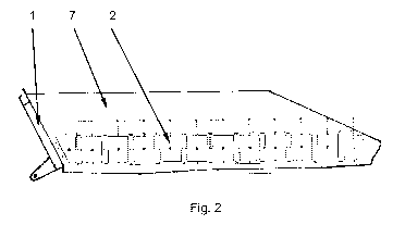
Figure 2 shows a view of the side wall of a chute with the
heating device accorded to the invention, said
side wall lying opposite the bucket wheel, and
Figure 3 shows a cross-sectional view of a heating element
with a wear-protection element arranged above the
latter.
Figure 1 and figure 2 show an arrangement of flexible
heating elements (2) on the side walls (7) of a chute (1)
for a bucket-wheel excavator. The flexible heating elements
(2) are adapted in their shape to the contour of the side
walls (7) and can thus be mounted close to the lower edge
of the side walls (7).
Figure 3 shows a cross-sectional representation of the
inventive arrangement of a flexible heating element (2)
between an outer wall (7) of the chute and a wear-
protection element (4).
A wear-protection element (4) of thickness 12 mm can be
seen, which together with spacing plates (5) is screwed by
means of countersunk screws M16 (8) to an outer wall (7) of
the chute. The wear-protection element (4) lies centrally
on a support plate (6) of diameter 50 mm, which is
connected to the outer wall (7) by means of a slot weld.
The flexible heating elements (2) comprise a central
cutout, with which they are advantageously fixed on the
support plates (6) during assembly on the inclined walls.
Over the thickness of the spacing plates (5), it is
possible to adjust the depth of the pocket which is formed

CA 02942712 2016-09-14
- 7 -
by the spacing plates arranged all around and in which the
flexible heating element (2) is arranged protected against
contact with conveyed material. In the specific case of
application, the spacing plates are 5 mm thick. The
flexible heating elements (2) lie with their thermal
insulation layer (3) on the outer wall (7) of the chute. A
platinum measuring resistor (9), which detects the heating
temperature, is inserted into a pocket-shaped recess of the
flexible heating element. The connecting cables of the
flexible heating element and the temperature sensor are led
out via bores in the wall elements.

CA 02942712 2016-09-14
- 8 -
List of reference numbers
1 chute
2 flexible heating element
3 thermal insulation layer
4 wear-protection element
spacing plate
6 support plate
7 outer wall
8 countersunk screw
9 temperature measuring element
electrical connecting cable

Representative Drawing
A single figure which represents the drawing illustrating the invention.
Administrative Status

2024-08-01:As part of the Next Generation Patents (NGP) transition, the Canadian Patents Database (CPD) now contains a more detailed Event History, which replicates the Event Log of our new back-office solution.

Please note that "Inactive:" events refers to events no longer in use in our new back-office solution.

For a clearer understanding of the status of the application/patent presented on this page, the site Disclaimer , as well as the definitions for Patent , Event History , Maintenance Fee  and Payment History  should be consulted.

Event History

Description Date
Inactive: Dead - No reply to s.30(2) Rules requisition 2019-02-28
Application Not Reinstated by Deadline 2019-02-28
Deemed Abandoned - Failure to Respond to Maintenance Fee Notice 2018-03-06
Inactive: Abandoned - No reply to s.30(2) Rules requisition 2018-02-28
Change of Address or Method of Correspondence Request Received 2018-01-09
Inactive: S.30(2) Rules - Examiner requisition 2017-08-28
Inactive: Report - QC passed 2017-08-10
Inactive: Cover page published 2016-10-27
Inactive: IPC assigned 2016-10-05
Letter Sent 2016-10-04
Inactive: First IPC assigned 2016-10-03
Inactive: Notice - National entry - No RFE 2016-09-29
Request for Examination Requirements Determined Compliant 2016-09-26
All Requirements for Examination Determined Compliant 2016-09-26
Request for Examination Received 2016-09-26
Application Received - PCT 2016-09-23
Inactive: IPC assigned 2016-09-23
National Entry Requirements Determined Compliant 2016-09-14
Application Published (Open to Public Inspection) 2015-09-17

Abandonment History

Abandonment Date Reason Reinstatement Date
2018-03-06

Maintenance Fee

The last payment was received on 2017-01-30

Note : If the full payment has not been received on or before the date indicated, a further fee may be required which may be one of the following

  • the reinstatement fee;
  • the late payment fee; or
  • additional fee to reverse deemed expiry.

Please refer to the CIPO Patent Fees web page to see all current fee amounts.

Fee History

Fee Type Anniversary Year Due Date Paid Date
Basic national fee - standard 2016-09-14
Request for examination - standard 2016-09-26
MF (application, 2nd anniv.) - standard 02 2017-03-06 2017-01-30
Owners on Record

Note: Records showing the ownership history in alphabetical order.

Current Owners on Record
TAKRAF GMBH
Past Owners on Record
STEFFEN NOWAK
THOMAS STENZEL
Past Owners that do not appear in the "Owners on Record" listing will appear in other documentation within the application.
Documents

To view selected files, please enter reCAPTCHA code :


To view images, click a link in the Document Description column. To download the documents, select one or more checkboxes in the first column and then click the "Download Selected in PDF format (Zip Archive)" or the "Download Selected as Single PDF" button.

List of published and non-published patent-specific documents on the CPD .

If you have any difficulty accessing content, you can call the Client Service Centre at 1-866-997-1936 or send them an e-mail at CIPO Client Service Centre.


Document
Description 
Date
(yyyy-mm-dd) 
Number of pages   Size of Image (KB) 
Description 2016-09-14 8 255
Representative drawing 2016-09-14 1 20
Claims 2016-09-14 3 68
Drawings 2016-09-14 1 34
Abstract 2016-09-14 1 19
Cover Page 2016-10-27 1 58
Courtesy - Abandonment Letter (Maintenance Fee) 2018-04-17 1 174
Courtesy - Abandonment Letter (R30(2)) 2018-04-11 1 166
Acknowledgement of Request for Examination 2016-10-04 1 177
Notice of National Entry 2016-09-29 1 195
Reminder of maintenance fee due 2016-11-08 1 112
International search report 2016-09-14 14 414
Amendment - Abstract 2016-09-14 2 97
National entry request 2016-09-14 4 83
Request for examination 2016-09-26 1 42
Examiner Requisition 2017-08-28 4 225